EP1094016A1 - Conveying device for liquids - Google Patents
Conveying device for liquids Download PDFInfo
- Publication number
- EP1094016A1 EP1094016A1 EP00112460A EP00112460A EP1094016A1 EP 1094016 A1 EP1094016 A1 EP 1094016A1 EP 00112460 A EP00112460 A EP 00112460A EP 00112460 A EP00112460 A EP 00112460A EP 1094016 A1 EP1094016 A1 EP 1094016A1
- Authority
- EP
- European Patent Office
- Prior art keywords
- container
- tank
- containers
- mtr
- parts
- Prior art date
- Legal status (The legal status is an assumption and is not a legal conclusion. Google has not performed a legal analysis and makes no representation as to the accuracy of the status listed.)
- Granted
Links
Images


Classifications
-
- B—PERFORMING OPERATIONS; TRANSPORTING
- B65—CONVEYING; PACKING; STORING; HANDLING THIN OR FILAMENTARY MATERIAL
- B65D—CONTAINERS FOR STORAGE OR TRANSPORT OF ARTICLES OR MATERIALS, e.g. BAGS, BARRELS, BOTTLES, BOXES, CANS, CARTONS, CRATES, DRUMS, JARS, TANKS, HOPPERS, FORWARDING CONTAINERS; ACCESSORIES, CLOSURES, OR FITTINGS THEREFOR; PACKAGING ELEMENTS; PACKAGES
- B65D90/00—Component parts, details or accessories for large containers
- B65D90/02—Wall construction
- B65D90/08—Interconnections of wall parts; Sealing means therefor
-
- B—PERFORMING OPERATIONS; TRANSPORTING
- B65—CONVEYING; PACKING; STORING; HANDLING THIN OR FILAMENTARY MATERIAL
- B65D—CONTAINERS FOR STORAGE OR TRANSPORT OF ARTICLES OR MATERIALS, e.g. BAGS, BARRELS, BOTTLES, BOXES, CANS, CARTONS, CRATES, DRUMS, JARS, TANKS, HOPPERS, FORWARDING CONTAINERS; ACCESSORIES, CLOSURES, OR FITTINGS THEREFOR; PACKAGING ELEMENTS; PACKAGES
- B65D88/00—Large containers
- B65D88/02—Large containers rigid
- B65D88/06—Large containers rigid cylindrical
-
- B—PERFORMING OPERATIONS; TRANSPORTING
- B65—CONVEYING; PACKING; STORING; HANDLING THIN OR FILAMENTARY MATERIAL
- B65D—CONTAINERS FOR STORAGE OR TRANSPORT OF ARTICLES OR MATERIALS, e.g. BAGS, BARRELS, BOTTLES, BOXES, CANS, CARTONS, CRATES, DRUMS, JARS, TANKS, HOPPERS, FORWARDING CONTAINERS; ACCESSORIES, CLOSURES, OR FITTINGS THEREFOR; PACKAGING ELEMENTS; PACKAGES
- B65D88/00—Large containers
- B65D88/02—Large containers rigid
- B65D88/12—Large containers rigid specially adapted for transport
- B65D88/128—Large containers rigid specially adapted for transport tank containers, i.e. containers provided with supporting devices for handling
Definitions
- the invention relates to a transport device for Liquids.
- Metal sheet is now the most used Construction material and at the same time much cheaper than e.g. coated fabric, but above all is sheet metal as "classic" material with excellent strength values extremely predictable.
- Tanks from e.g. coated steel sheet, Niro, or coated aluminum alloy are related to their Usability much more versatile and unproblematic than Coated fabric tanks. Also stand nowadays sophisticated and modern sheet metal coating processes for Available. Furthermore, it should be clear that there are tank inlets made of sheet metal with virtually no leakage and abrasion problems will give.
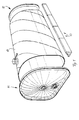
- the SIT system essentially consists of a spiral welded, tubular mantle and two almost identical End plates made from deep-drawn sheet metal. The items will be shortly before delivery to the shipper for the tank inlay assembled and inserted into the standard container (Fig. 1). Then the system is ready to load and can Shippers survive. Of course it is also possible or occasionally sensible, the assembly of the tank inlays by the Let shippers do it themselves. Need with practice two men for the whole assembly about 10 to 15 minutes.
- the Wedge pieces are needed as lining pieces to the tank inlay during the loading process in the transition area from the floor to the Support side wall and must be installed in the Containers are inserted.
- the front faceplate is smooth, the rear faceplate has three connections: one connection in the lower area for filling or emptying the tank, a central connection for washing the tank (for the Spray lance) and a connection in the upper area Venting / ventilation when loading / unloading the tank.
- the key element of the construction is the closure "Jacket tube / end plate".
- the closure can be made irreversible (irreversible) may, or must be designed to be reversible.
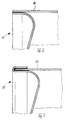
- An unsolvable Closure is relatively easy to assemble, e.g. by Gluing or soldering (Fig. 2, 3). He should be far for that most applications are possible, e.g. for all Disposable applications and various reusable applications in which the tank can be washed easily.
- Detachable closures are more complex even as quick-release fastener, simply because that the assembly and disassembly work in each one Application must be repeated.
- the main advantage Detachable closures consist of disassembled empty containers can simply be transported much more cost-effectively, especially over long distances, of course. Here it is important Weigh the technical advantages and disadvantages of the processing.
- the systems according to the invention are sold and marketed by worldwide forwarding and shipping companies. They are stocked as kits in licensed depots and installed (fitted) in standard containers upon delivery to the shipper. The system can then be filled in a similar way to a tank container. Systems used in one-way traffic are scrapped after use. Reusable systems are washed in a licensed depot or immediately after unloading at the unloader and kept ready for the next use. Use for products of the same type in a product group is permitted, ie that only food may be transported in tank inlays that are intended for foodstuffs and not chemicals in between. However, it is also permissible to downgrade a food tank from e.g. B. food on chemicals, just not the other way around. Corresponding notes are located on the rear end plate of the tank inlay.
- Essential features of the present invention are on the one hand the container and on the other hand the holder of this container in Transport container.
- the container has a cylindrical or semi-cylindrical one Proven shape or modified designs, where the optimal shape corresponds to that of a loaf of bread.
- the containers can now be designed so that you can stretch them into each other can, if they are to be transported empty. If one uses longitudinally divided container halves, so can be slightly tapered and inserted into each other become.
- connection options for the container parts are Seals in a wide variety of designs that be well mastered purely in terms of technology.
- the container is divided into a middle bulkhead with an inflatable seal insert through which the two container parts, if desired, from each other can be sealed and immediately the tight connection of the both container segments is accomplished to the outside.
- Fig. 1 shows with 10 a cylinder jacket that spiral welded sheet with a thickness in the range of 1 mm has been produced.
- This cylinder jacket 10 becomes both ends firmly closed with lids 11 and 12, the covers 11 and 12 can have the same structure or are designed differently.
- Fig. 2 shows an enlarged scale one way to Solder the lid 11 to the jacket 10.
- Fig. 3 shows a correspondingly enlarged scale Bond point.
- Figures 5 and 6 show end views of the Container 10, 11, 12, in one embodiment the jacket 10 retains its cylindrical shape while in the another embodiment, the jacket 17 has an arched shape can assume that essentially the interior of the container 20 corresponds.
- Fig. 7 shows nested shell parts 10 which are on this Way inside a shipping container to one Manufacturing location can be transported.
- the manufactured The jacket parts are slightly deformed and then pushed together, so the five nested coats shown just the The length that a coat has for itself.
- the inside of the jackets 10 is first removed and with the two end parts connected to a container 10, 11, 12.
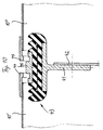
- the extension of the registration to two-part systems shows the Fig. 10. It is necessary that the cups 10 'and 10' ' (Cups) are tapered so they are stacked together economical as empties (20 to 30 pieces in a container) can be transported. The assembly is reduced by two Layers on one layer. The tie rods and a seal. In addition, there is a middle bulkhead 41 and 42, that may seem more complex at first, but many Offers advantages. It is essential that the cup shape and the middle bulkhead achieves considerable dimensional stability, which is indispensable especially for thin-walled constructions.
- the dynamic locking and sealing mechanism 43 to 46 ensures a high level of functional Safety, especially when deformed in the event of an accident is significant.
- the cup shape with the shown locking mechanism should be in the material variant made of stainless steel sheet now especially recommended for hazardous goods applications, where then only the wall thickness would have to be increased.
Abstract
Description
Die Erfindung bezieht sich auf eine Transportvorrichtung für Flüssigkeiten.The invention relates to a transport device for Liquids.
Bulktransporte von Flüssigkeiten werden üblicherweise in Tank-Containern oder flexiblen Behältern durchgeführt. Nun ist es bekannt, dass der Hauptvorteil eines sog. Flexitanks gegenüber einem Tank-Container darin besteht, dass er in fast allen Anwendungsfällen beträchtliche Kostenvorteile bietet. Nachteilig ist jedoch, dass Tanks aus Gummi oder Kunststoff stets relativ leckageanfällig und daher überaus empfindlich sind. Sie erfordern einen erheblichen Aufwand an Handling, an Sorgfalt, Überwachung und ständiger Wartung. Das hiermit einhergehende nicht unbeträchliche Risiko ist bei aller Sorgfalt stets latent, einfach weil die Tanks durch viele Hände gehen und es dabei in der Kette immer wieder Menschen geben wird, die bei so komplexen Systemen überfordert sind. Angesichts dieser Problematik bemühen sich alle Flexitank-Anbieter um einen möglichst hoch qualifizierten Service.Bulk transport of liquids is usually carried out in tank containers or flexible containers. Now it is announced that the main advantage over a so-called flexitank a tank container is that it can be found in almost all Use cases offers considerable cost advantages. Disadvantageous is that rubber or plastic tanks are always relative are prone to leakage and are therefore extremely sensitive. she require a considerable amount of handling, care, Monitoring and constant maintenance. The accompanying With great care, not inconsiderable risk is always latent, simply because the tanks go through many hands and get it in the chain will always give people who are so complex Systems are overwhelmed. In view of this problem, make an effort all Flexitank providers are as high as possible qualified service.
Wie nun aber müsste ein technisch fortschrittliches Transport-tank-System beschaffen sein, damit die angerissenen Risiko-Faktoren und Nachteile vermieden werden können, ohne dabei auf Kostenvorteile verzichten zu müssen? Und nicht nur das: Darüber hinaus werden von einem fortschrittlichen System noch zusätzliche Vorteile erwartet, um unter ständig wachsendem Preisdruck längerfristig wettbewerbsfähig sein zu können.But how would a technically advanced transport tank system be? be prepared so that the risk factors outlined and disadvantages can be avoided without going on Do you have to forego cost advantages? And not only that: about it in addition to being an advanced system additional benefits are expected to grow among To be able to remain competitive in the long term.
Die Antwort auf die vorgelegten Fragen ist eine Neuentwicklung "Steel-Inlay-Tank-System" oder "Sheet-Inlay-Tank-System" oder auch graduated/composed Stagger-Inlay-Tank-System".The answer to the questions asked is a new development "Steel inlay tank system" or "Sheet inlay tank system" or also graduated / composed stagger inlay tank system ".
Das SIT-System basiert auf folgenden Überlegungen:
Nun ist Metallblech das am meisten verwendete Konstruktionsmaterial und dabei sehr viel preiswerter als z.B. beschichtetes Gewebe, vor allem aber ist Metallblech als "klassisches" Material mit ausgezeichneten Festigkeitswerten überaus berechenbar. Tanks aus z.B. beschichtetem Stahlblech, Niro, oder beschichteter Alu-Legierung sind in Bezug auf ihre Verwendbarkeit wesentlich vielseitiger und unproblematischer als Tanks aus beschichtetem Gewebe. Auch stehen heutzutage raffinierte und modernste Blech-Beschichtungsverfahren zur Verfügung. Desweiteren dürfte feststehen, dass es mit Tank-Inlets aus Blech so gut wie keine Leckage- und Scheuerprobleme geben wird.Metal sheet is now the most used Construction material and at the same time much cheaper than e.g. coated fabric, but above all is sheet metal as "classic" material with excellent strength values extremely predictable. Tanks from e.g. coated steel sheet, Niro, or coated aluminum alloy are related to their Usability much more versatile and unproblematic than Coated fabric tanks. Also stand nowadays sophisticated and modern sheet metal coating processes for Available. Furthermore, it should be clear that there are tank inlets made of sheet metal with virtually no leakage and abrasion problems will give.
Nun würde es aus abwicklungstechnischen Gründen wenig Sinn machen, die Inlay-Tanks gleich im Produktionsbetrieb komplett zusammenzusetzen. Die Transportkosten der Leergebinde zum meist weit entfernten Einsatzort wären einfach zu hoch. Damit wäre das System von vornherein unrentabel, so dass noch ein weiterer Gedanke ins Spiel kommen muss, nämlich die Konzipierung als Bausatz (Kit).Now it would make little sense for processing reasons make the inlay tanks complete in the production plant put together. The transport costs of the empty containers for the most part far away location would simply be too high. That would be it System unprofitable from the start, so yet another Thought must come into play, namely the conception as Kit.
Um die Sache nun richtig rund zu machen, muss noch eine weitere Bedingung erfüllt werden: Das System muss so leicht und einfach sein, dass eine Montage vor Ort mit minimalem Aufwand vonstatten gehen kann und auch die Versandkosten erträglich niedrig ausfallen. Dies wiederum ist möglich durch die besondere Bauweise des SIT-Systems. Last-but-not-least kann sich ein neues System nur dann mit Erfolg am Markt durchsetzen, wenn hiermit ein großes Bedarfspotential gedeckt werden kann, und zwar sowohl in Bezug auf die Stückzahl als auch auf die Anforderungen. Dies wiederum ergibt sich so ganz nebenbei durch die konsequente Anwendung des KIT-Konzepts in maschineller Serienfertigung, ohne dass hierbei jedoch die Variationsbreite des Systems unvorteilhaft eingeengt wird: Es besteht ja die Möglichkeit, verschiedene Blechwerkstoffe mit verschiedenen Beschichtungstechniken zu kombinieren.To make things really round, there has to be another one Condition must be met: The system must be so light and simple be that on-site assembly can be carried out with minimal effort can go and the shipping costs are tolerably low fail. This in turn is possible due to the special Construction of the SIT system. Last but not least, a new one Only implement the system successfully on the market if you do so a large potential need can be met, both in terms of quantity as well as requirements. This again, by the way, this results from the consequent Application of the KIT concept in machine series production, without however, that the range of variation of the system is disadvantageous is narrowed down: there is the possibility of different Sheet materials with different coating techniques too combine.
Das SIT-System besteht im wesentlichen aus einem spiralverschweißten, röhrenförmigen Mantel und zwei nahezu identischen Stirnplatten aus tiefgezogenem Blech. Die Einzelteile werden kurz vor Auslieferung an den Verlader zum Tank-Inlay zusammengesetzt und in den Standard-Container eingeschoben (Fig. 1). Danach ist das System beladefertig und kann dem Verlader übersteht werden. Natürlich ist es auch möglich bzw. gelegentlich sinnvoll, die Montage der Tank-Inlays durch den Verlader selbst durchführen zu lassen. Mit etwas Übung brauchen zwei Mann für die ganze Montage etwa 10 bis 15 Minuten.The SIT system essentially consists of a spiral welded, tubular mantle and two almost identical End plates made from deep-drawn sheet metal. The items will be shortly before delivery to the shipper for the tank inlay assembled and inserted into the standard container (Fig. 1). Then the system is ready to load and can Shippers survive. Of course it is also possible or occasionally sensible, the assembly of the tank inlays by the Let shippers do it themselves. Need with practice two men for the whole assembly about 10 to 15 minutes.
In einem Beipack zum Bausatz befinden sich Keilstücke aus Styropor bzw. Luftkissen (Fig. 1 sowie Fig. 5 und 6). Die Keilstücke werden als Futterstücke benötigt, um das Tank-Inlay während des Beladevorgangs im Übergangsberich vom Boden zur Seitenwand zu stützen und müssen bei der Montage in den Container eingelegt werden. Die vordere Stirnplatte ist glatt, die hintere Stirnplatte besitzt drei Anschlüsse: Einen Anschluss im unteren Bereich zur Befüllung bzw. Entleerung des Tanks, einen Zentral-Anschluss zum Waschen des Tanks (für die Sprühlanze) und einen Anschluss im oberen Bereich zur Entlüftung/Belüftung bei der Beladung/Entladung des Tanks. There are wedge pieces in an accessory pack for the kit Styrofoam or air cushion (Fig. 1 and Fig. 5 and 6). The Wedge pieces are needed as lining pieces to the tank inlay during the loading process in the transition area from the floor to the Support side wall and must be installed in the Containers are inserted. The front faceplate is smooth, the rear faceplate has three connections: one connection in the lower area for filling or emptying the tank, a central connection for washing the tank (for the Spray lance) and a connection in the upper area Venting / ventilation when loading / unloading the tank.
Das Schlüsselelement der Konstruktion ist der Verschluss "Mantelrohr/Stirnplatte". Hier gibt es grundsätzlich zwei verschiedene Möglichkeiten der Konstruktion, wobei abzuklären ist, ob der Verschluss unlösbar (irreversibel) hergestellt sein darf, oder lösbar (reversibel) ausgeführt sein muss. Letztlich ist dies eine rein abwicklungstechnische Frage. Ein unlösbarer Verschluss ist relativ einfach zu montieren, - z.B. durch Klebung oder Lötung (Fig. 2, 3). Er dürfte für die weitaus meisten Anwendungsfälle in Frage kommen, so z.B. für alle Einweg-Anwendungen und diverse Mehrweg-Einsatzfälle, in denen der Tank problemlos gewaschen werden kann. Lösbare Verschlüsse sind selbst als Schnellverschluss aufwendiger, allein dadurch, dass die Montage- und Demontagearbeiten in jedem einzelnen Einsatzfall wiederholt werden müssen. Der wesentliche Vorteil lösbarer Verschlüsse besteht darin, dass zerlegte Leergebinde einfach erheblich kostengünstiger transportiert werden können, vor allem natürlich über weite Entfernungen. Hier gilt es, abwicklungstechnische Vor- und Nachteile gegeneinander abzuwägen.The key element of the construction is the closure "Jacket tube / end plate". There are basically two here different construction options, being clarified is whether the closure can be made irreversible (irreversible) may, or must be designed to be reversible. Ultimately this is a purely technical issue. An unsolvable Closure is relatively easy to assemble, e.g. by Gluing or soldering (Fig. 2, 3). He should be far for that most applications are possible, e.g. for all Disposable applications and various reusable applications in which the tank can be washed easily. Detachable closures are more complex even as quick-release fastener, simply because that the assembly and disassembly work in each one Application must be repeated. The main advantage Detachable closures consist of disassembled empty containers can simply be transported much more cost-effectively, especially over long distances, of course. Here it is important Weigh the technical advantages and disadvantages of the processing.
Nun gibt es auch eine Reihe von Sonderanwendungen mit speziellen Auflagen, für die bewährtes Zusatzgerät zur Verfügung gestellt werden kann. So. z.B. gibt es für Transporte mit besonders hohen Sicherheitsauflagen zusätzliche Auffangwannen und für Fälle, in denen das Produkt beheizt gefahren werden muss, sehr preiswerte und leicht einbaubare handelsübliche Heizbänder. Natürlich können auch auf das System zugeschnittene Isolierdecken gestellt bzw. geliefert werden.Now there are also a number of special applications with special ones Requirements provided for the proven additional device can be. E.g. is available for transports with particularly high loads Safety requirements additional sumps and for cases in where the product has to be driven heated, very inexpensive and easily installable standard heating tapes. Naturally can also put insulating blankets tailored to the system or delivered.
Das System kann nahezu unbegrenzt eingesetzt werden, und zwar für
- alle Nahrungsmittel, Mineralöl- und Schmierstoffprodukte und nahezu alle Chemikalien,
- besonders verderbliche Nahrungsmittel, wie z. B. Milch, Tomatenmark, Orangensaftkonzentrate, Frischsäfte usw. Für derartige Transportaufgaben kann das SIT-System aseptisch eingestellt werden,
- Produkte, die warm oder selbst heiß gefahren werden müssen. Hierfür steht ein handelsübliches und leicht einbaubares Heizsystem, ggfs. in Kombination mit Isolierdecken, zur Verfügung.
- besondes zähe, schwerfließende Produkte wie z.B. Druckerschwärze, Honig usw.
- Gefahrgut nach Prüfung und Freigabe.
- all food, mineral oil and lubricant products and almost all chemicals,
- particularly perishable foods, such as B. milk, tomato paste, orange juice concentrates, fresh juices etc. For such transport tasks, the SIT system can be set aseptically,
- Products that need to be driven warm or even hot. A commercially available and easily installed heating system is available for this, possibly in combination with insulating ceilings.
- particularly tough, difficult-flowing products such as printing ink, honey, etc.
- Dangerous goods after testing and approval.
Die Systeme gemäß der Erfindung sind wesentlich preisgünstiger
als Flexitanks oder etwa Tank-Container;
Die Systeme gemäß der Erfindung werden über weltweit vertretene
Speditions- und Schifffahrtsgesellschaften vertrieben und in
Verkehr gebracht. Sie werden in lizensierten Depots als Bausätze
bevorratet und bei Auslieferung an den Verlader in Standard-Container
eingebaut (gefittet). Das System kann dann auf
ähnliche Weise wie ein Tank-Container befüllt werden.
Im Einweg-Verkehr eingesetzte Systeme werden nach dem Einsatz
verschrottet. Mehrweg-Systeme werden in einem lizensierten Depot
oder schon gleich nach Entladung beim Ablader gewaschen und für
den nächsten Einsatz bereitgehalten. Eine Nutzung für artgleiche
Produkte einer Produktgruppe ist zulässig, d.h. dass in Tank-Inlays,
die für Nahrungsmittel vorgesehen sind, auch nur noch
Nahrungsmittel transportiert werden dürfen und nicht etwa
zwischendurch einmal Chemikalien. Allerdings ist es auch
zulässig, einen Nahrungsmitteltank runterzustufen von z. B.
Nahrungsmittel auf Chemikalien, nur eben nicht umgekehrt.
Entsprechende Vermerke befinden sich auf der hinteren
Stirnplatte des Tank-Inlays.The systems according to the invention are sold and marketed by worldwide forwarding and shipping companies. They are stocked as kits in licensed depots and installed (fitted) in standard containers upon delivery to the shipper. The system can then be filled in a similar way to a tank container.
Systems used in one-way traffic are scrapped after use. Reusable systems are washed in a licensed depot or immediately after unloading at the unloader and kept ready for the next use. Use for products of the same type in a product group is permitted, ie that only food may be transported in tank inlays that are intended for foodstuffs and not chemicals in between. However, it is also permissible to downgrade a food tank from e.g. B. food on chemicals, just not the other way around. Corresponding notes are located on the rear end plate of the tank inlay.
Die folgenden Tabellenwerte basieren auf der idealisierten
Annahme eines kreisrunden liegenden Zylinders. Hiervon wurde bei
der Berechnung der Cubagen zunächst einmal ausgegangen. Der dann
tatsächlich auskonstruierte Querschnitt entspricht einem unten
abgeplatteten Zylinder, etwa wie ein Brotlaib, wodurch sich die
Höhe des Tanks verringert und die Breite bis auf Containerbreite
ausdehnt.
Dieser Tabelle ist zu entnehmen, dass - einmal abgesehen von der Sondergröße - nur Stirnplatten in zwei Größen benötigt werden, um das ganze Programm abzudecken. Die Längen bewegen sich - einmal abgesehen von der Zwischengröße "19 cbm" - zwischen 5.05 und 5.80 mtr. This table shows that - apart from the Special size - only end plates in two sizes are required to cover the whole program. The lengths move - apart from the intermediate size "19 cbm" - between 5.05 and 5.80 mtr.
Wesentliche Merkmale der vorliegenden Erfindung sind einerseits der Behälter und andererseits die Halterung dieses Behälters im Transportcontainer.Essential features of the present invention are on the one hand the container and on the other hand the holder of this container in Transport container.
Bei dem Behälter haben sich eine zylindrische oder halbzylindrische Form oder abgewandelte Gestaltungen bewährt, wobei die optimale Form der eines Brotlaibes entspricht. Die Behälter können nun so ausgestaltet sein, dass man sie ineinanderstrecken kann, wenn sie im Leerzustand transportiert werden sollen. Verwendet man in Längsrichtung quergeteilte Behälterhälften, so können diese leicht konisch ausgeführt und ineinandergesteckt werden.The container has a cylindrical or semi-cylindrical one Proven shape or modified designs, where the optimal shape corresponds to that of a loaf of bread. The containers can now be designed so that you can stretch them into each other can, if they are to be transported empty. If one uses longitudinally divided container halves, so can be slightly tapered and inserted into each other become.
Die Verbindungsmöglichkeiten für die Behälterteile sind Dichtungen in den unterschiedlichsten Ausführungsformen, die rein von der Technik her gut beherrscht werden. Bei dem in Längsrichtung quergeteilten Behälter findet eine Mittelschottwand mit einer aufblasbaren Dichtung Einsatz, durch die die beiden Behälterteile, wenn dies gewünscht wird, voneinander abgedichtet werden können und sogleich die dichte Verbindung der beiden Behältersegmenten nach außen hin bewerkstelligt wird.The connection options for the container parts are Seals in a wide variety of designs that be well mastered purely in terms of technology. At the in In the longitudinal direction, the container is divided into a middle bulkhead with an inflatable seal insert through which the two container parts, if desired, from each other can be sealed and immediately the tight connection of the both container segments is accomplished to the outside.
Die Erfindung wird nachstehend anhand der Zeichnung beispielsweise erläutert.
- Fig. 1
- zeigt eine schaubildliche Ansicht einer Vorrichtung zum Transport von Flüssigkeiten gemäß der Erfindung.
- Die Fig. 2 bis 4
- zeigen in vergrößertem Maßstab Verbindungsmöglichkeiten zwischen dem mehr oder weniger zylindrischen Teil und den Stirnseitenteilen einer Vorrichtung gemäß der Erfindung.
- Fig. 5
- zeigt eine stirnseitige Ansicht eines zylindrischen Behälters innerhalb eines handelsüblichen Containers.
- Fig. 6
- zeigt eine stirnbildliche Ansicht eines ausgewölbten zylinderischen Behälters in einem Container.
- Fig. 7
- zeigt eine Vorderansicht einer Mehrzahl von ineinander gesteckten im wesentlichen zylindrischen Teilen einer Vorrichtung gemäß der Erfindung.
- Fig. 8
- zeigt einen Längsquerschnitt durch eine andere Ausführungsform eines Behälters gemäß der Erfindung mit innenliegenden Zugankern.
- Fig. 9
- zeigt einen Längsquerschnitt durch eine andere Ausführungsform eines Behälters gemäß der Erfindung mit außenliegenden Zugankern.
- Fig. 10
- zeigt in geändertem Maßstab die Verbindungsstelle von zwei Behältersegmenten mit einer Mittelschottwand.
- Fig. 11
- zeigt eine Querschnittsansicht durch einen Behälter gemäß der Erfindung mit idealer Querschnittsgestaltung.
- Fig. 1
- shows a perspective view of a device for transporting liquids according to the invention.
- 2 to 4
- show on an enlarged scale connection options between the more or less cylindrical part and the end face parts of a device according to the invention.
- Fig. 5
- shows an end view of a cylindrical container within a commercially available container.
- Fig. 6
- shows a front view of a bulged cylindrical container in a container.
- Fig. 7
- shows a front view of a plurality of nested substantially cylindrical parts of a device according to the invention.
- Fig. 8
- shows a longitudinal cross section through another embodiment of a container according to the invention with internal tie rods.
- Fig. 9
- shows a longitudinal cross section through another embodiment of a container according to the invention with external tie rods.
- Fig. 10
- shows in a modified scale the connection point of two container segments with a middle bulkhead.
- Fig. 11
- shows a cross-sectional view through a container according to the invention with ideal cross-sectional design.
Fig. 1 zeigt mit 10 einen Zylindermantel, der aus
spiralverschweißtem Feinblech mit einer Dicke im Bereich von
1 mm hergestellt worden ist. Dieser Zylindermantel 10 wird zu
beiden Stirnseiten mit Deckeln 11 und 12 fest verschlossen,
wobei die Deckel 11 und 12 den gleichen Aufbau haben können oder
unterschiedlich gestaltet sind.Fig. 1 shows with 10 a cylinder jacket that
spiral welded sheet with a thickness in the range of
1 mm has been produced. This
Mit 13 sind Füllstücke aus Schaumstoff bezeichnet, die zusammen
mit dem Behälter 10, 11 und 12 in einem handelsüblichen
Container untergebracht werden, um den Transport des Behälters
10, 11, 12 zu bewerkstelligen.With 13 fillers made of foam are referred to, which together
with the
Fig. 2 zeigt in vergrößertem Maßstab eine Möglichkeit zum
Verlöten des Deckels 11 mit dem Mantel 10.Fig. 2 shows an enlarged scale one way to
Solder the
Fig. 3 zeigt in entsprechend vergrößertem Maßstab eine Verklebungsstelle.Fig. 3 shows a correspondingly enlarged scale Bond point.
Fig. 4 zeigt die Möglichkeit, wie die Einzelteile 10 und 11 bzw.
10 und 12 zusammengesetzt werden können, so dass ohne weiteres
die Teile voneinander getrennt werden können.4 shows the possibility of how the
Im Randbereich des Deckelteils 11 und des Zylindermantels 10
befindet sich Dichtungsmasse, und bei einem genügend großen
Innendruck wird dadurch sichergestellt, dass eine flüssigkeitsdichte
Verbindung zwischen Innen- und Außenraum möglich ist,
ohne dass diese Verbindung nicht gelöst werden könnte.In the edge area of the
Die Figuren 5 und 6 zeigen stirnseitige Ansichten auf den
Behälter 10, 11, 12, und zwar in der einen Ausführungsform
behält der Mantel 10 seine zylindrische Gestalt, während in der
anderen Ausführungsform der Mantel 17 eine ausgewölbte Form
annehmen kann, die im wesentlichen dem Innenraum des Containers
20 entspricht.Figures 5 and 6 show end views of the
Aus Sicherheitsgründen könnte sich im Inneren des Containers 20
noch ein Auffangbecken befinden, so das bei einer Leckage des
Behälters 10, 11, 12 die austretende Flüssigkeit nicht aus dem
Innenraum des Containers 20 herausfließen kann.For security reasons, inside the
Desgleichen kann sich im Inneren des Behälters 10, 11, 12 eine
zusätzliche aufweitbare geschlossene Folie befinden, so dass
eine erhöhte Sicherheit während des Transportes erzielt werden
kann.Likewise, a inside of the
Fig. 7 zeigt ineinander geschobene Mantelteile 10, die auf diese
Art und Weise im Inneren eines Transportcontainers zu einem
Herstellungsort transportiert werden können. Die hergestellten
Mantelteil werden etwas verformt und dann ineinandergeschoben,
so dass die gezeigten fünf ineinandergeschobenen Mäntel nur die
Länge haben, die auch ein Mantel für sich hat. An Ort und Stelle
wird zunächst der Innere der Mäntel 10 entnommen und mit den
beiden Stirnseitenteilen zu einem Behälter 10, 11, 12 verbunden.Fig. 7 shows nested
Durch die zylindrische Ausbildung der Mäntel 10 können diese
dadurch ineinandergesteckt werden, dass sie im unteren Bereich,
so wie in Fig. 7 gezeigt, verformt werden.Due to the cylindrical design of the
Die beiden Zuganker-Konstruktionen (40) der Fig. 8 und 9 stellen
zwei weitere Varianten des Behälters 10 gemäß der Erfindung dar.
Diese beiden Lösungen betreffen anch wie vor dreiteilige
Systeme. Zuganker-Befestigungen sind jedoch sehr viel einfacher
und sicherer zu montieren, als Systeme mit Umfangsbefestigungen
der Deckel am Zylinder.Make the two tie rod constructions (40) of FIGS. 8 and 9
two further variants of the
Die optimierte Querschnittsgeometrie für den Behälter ist in Fig. 11 deutlich dargestellt, weil der weitaus größte Anwendungsbereich dünnwandiger hochbelastbarer Tankkonstruktionen genau nach diesem Querschnittsbild ausgeführt werden muss und wird. Die Abweichung von der rein zylindrischen Form. die für Druckgasbehälter ideal ist, ergibt sich für Flüssigladungen aus der dreieckigen Form der hydrostatischen Druckkennlinie. Diese Brotlaib-Form stellt sich auch bei der Beladung der flexiblen Tanks ein. Insofern wird hier für halbstarre Behälter (aus Blech) eine Idealform für dünnwandige Membranen nach dem Seifenhautmodell nachgebildet. Man kann sie auch als abgeplatteten Zylinder bezeichnen, der sich aus der Überlagerung einer rechteckigen mit einer dreieckigen vertikalen Druckkennlinie ergibt.The optimized cross-sectional geometry for the container is in Fig. 11 clearly shown because the largest by far Area of application for thin-walled, heavy-duty tank structures be carried out exactly according to this cross-sectional image must and will. The deviation from the purely cylindrical shape. which is ideal for pressurized gas containers results for Liquid charges from the triangular shape of the hydrostatic Pressure characteristic. This loaf of bread also appears in the Loading of the flexible tanks. In this respect, here for semi-rigid containers (made of sheet metal) an ideal shape for thin-walled Replica membranes based on the soap skin model. You can also referred to as a flattened cylinder, which results from the Superposition of a rectangular with a triangular vertical Pressure curve results.
Die Erweiterung der Anmeldung auf zweiteilige Systeme zeigt die
Fig. 10. Hierbei ist es notwendig, dass die Becher 10' und 10''
(Cups) konisch ausgebildete sind, damit sie ineinandergestapelt
als Leergut (20 bis 30 Stück in einem Container) wirtschaftlich
transportiert werden können. Die Montage reduziert sich von zwei
Ebenen auf eine Ebene. Zwar entfallen dabei die Zuganker und
eine Dichtung. Hinzu kommt jedoch ein Mittelschott 41 und 42,
das zwar zunächst aufwendiger erscheinen mag, aber viele
Vorteile bietet. Wesentlich ist, dass durch die Becherform und
das Mittelschott eine erhebliche Formstabilität erreicht wird,
die insbesondere für dünnwandige Konstruktionen unabdingbar ist.
Der dynamisch wirksame Verschluss- und Dichtigkeitsmechanismus
43 bis 46 gewährleistet ein hohes Maß an funktionaler
Sicherheit, was insbesondere bei Verformungen im Unfallgeschehen
bedeutsam ist. Die Dichtung 43 und der Verschluss 44-46 stellen
sich gewissermaßen stets und sofort selbstätig nach. Aufgeblasen
und abgesaugt wird der Gummischlauch 43 über ein Luftventil am
Außenumfang des Mittelschotts 41 in mittlerer Höhe im Halbkreis
der Deckensektion 10' bzw. 10''. Das Ventil kann daher nicht an
der Containerwand scheuern und ist auch noch bei beladenem Tank
zugänglich.The extension of the registration to two-part systems shows the
Fig. 10. It is necessary that the cups 10 'and 10' '
(Cups) are tapered so they are stacked together
economical as empties (20 to 30 pieces in a container)
can be transported. The assembly is reduced by two
Layers on one layer. The tie rods and
a seal. In addition, there is a
Die Becherform mit dem dargestellten Verschlussmechanismus dürfte sich in der Materialvariante aus Edelstahlblech nun besonders auch für Gefahrgut-Anwendungen empfehlen, wobei dann lediglich die Wanddicke erhöht werden müsste.The cup shape with the shown locking mechanism should be in the material variant made of stainless steel sheet now especially recommended for hazardous goods applications, where then only the wall thickness would have to be increased.
Claims (3)
Applications Claiming Priority (2)
| Application Number | Priority Date | Filing Date | Title |
|---|---|---|---|
| DE19950449 | 1999-10-19 | ||
| DE19950449 | 1999-10-19 |
Publications (2)
| Publication Number | Publication Date |
|---|---|
| EP1094016A1 true EP1094016A1 (en) | 2001-04-25 |
| EP1094016B1 EP1094016B1 (en) | 2004-03-10 |
Family
ID=7926230
Family Applications (1)
| Application Number | Title | Priority Date | Filing Date |
|---|---|---|---|
| EP00112460A Expired - Lifetime EP1094016B1 (en) | 1999-10-19 | 2000-06-10 | Conveying device for liquids |
Country Status (9)
| Country | Link |
|---|---|
| EP (1) | EP1094016B1 (en) |
| CN (1) | CN1382093A (en) |
| AT (1) | ATE261381T1 (en) |
| AU (1) | AU7917900A (en) |
| BR (1) | BR0014886A (en) |
| DE (1) | DE50005585D1 (en) |
| RU (1) | RU2002113085A (en) |
| WO (1) | WO2001028891A1 (en) |
| ZA (1) | ZA200202558B (en) |
Cited By (4)
| Publication number | Priority date | Publication date | Assignee | Title |
|---|---|---|---|---|
| WO2006045549A1 (en) * | 2004-10-26 | 2006-05-04 | Lohse Juergen | Tank transport system |
| DE102010020747A1 (en) | 2010-05-17 | 2011-11-17 | Jörg Heinz Lohse | Tank transport system for e.g. non-hazardous materials and hazardous materials, has material-moderate plastic foils or side folded tubes provided for resin of hard cell-tank and for inner liner |
| JP2013108692A (en) * | 2011-11-22 | 2013-06-06 | Shikoku Electric Power Co Inc | Tank |
| FR3011831A1 (en) * | 2013-10-11 | 2015-04-17 | Aci Holding | IMPROVING THE DIMENSIONAL STABILITY OF THE TANKS |
Families Citing this family (2)
| Publication number | Priority date | Publication date | Assignee | Title |
|---|---|---|---|---|
| CN102514852A (en) * | 2011-11-24 | 2012-06-27 | 芜湖中集瑞江汽车有限公司 | Manufacture process for chemical liquid conveying tank truck barrel body |
| CN104443891A (en) * | 2013-09-17 | 2015-03-25 | 南通中集罐式储运设备制造有限公司 | Tank container |
Citations (3)
| Publication number | Priority date | Publication date | Assignee | Title |
|---|---|---|---|---|
| FR2060254A1 (en) * | 1969-09-24 | 1971-06-18 | Millet Louis | |
| FR2715385A1 (en) * | 1994-01-25 | 1995-07-28 | Chateauneuf Sa Atel Polyvalent | Large volume modular storage tank |
| US5911337A (en) * | 1995-10-04 | 1999-06-15 | Bedeker; James E. | Vessel for a shipping container |
-
2000
- 2000-06-10 AT AT00112460T patent/ATE261381T1/en not_active IP Right Cessation
- 2000-06-10 DE DE50005585T patent/DE50005585D1/en not_active Expired - Fee Related
- 2000-06-10 EP EP00112460A patent/EP1094016B1/en not_active Expired - Lifetime
- 2000-10-11 RU RU2002113085/12A patent/RU2002113085A/en not_active Application Discontinuation
- 2000-10-11 WO PCT/EP2000/009981 patent/WO2001028891A1/en active Application Filing
- 2000-10-11 CN CN00814569A patent/CN1382093A/en active Pending
- 2000-10-11 AU AU79179/00A patent/AU7917900A/en not_active Abandoned
- 2000-10-11 BR BR0014886-5A patent/BR0014886A/en not_active Application Discontinuation
-
2002
- 2002-04-02 ZA ZA200202558A patent/ZA200202558B/en unknown
Patent Citations (3)
| Publication number | Priority date | Publication date | Assignee | Title |
|---|---|---|---|---|
| FR2060254A1 (en) * | 1969-09-24 | 1971-06-18 | Millet Louis | |
| FR2715385A1 (en) * | 1994-01-25 | 1995-07-28 | Chateauneuf Sa Atel Polyvalent | Large volume modular storage tank |
| US5911337A (en) * | 1995-10-04 | 1999-06-15 | Bedeker; James E. | Vessel for a shipping container |
Cited By (4)
| Publication number | Priority date | Publication date | Assignee | Title |
|---|---|---|---|---|
| WO2006045549A1 (en) * | 2004-10-26 | 2006-05-04 | Lohse Juergen | Tank transport system |
| DE102010020747A1 (en) | 2010-05-17 | 2011-11-17 | Jörg Heinz Lohse | Tank transport system for e.g. non-hazardous materials and hazardous materials, has material-moderate plastic foils or side folded tubes provided for resin of hard cell-tank and for inner liner |
| JP2013108692A (en) * | 2011-11-22 | 2013-06-06 | Shikoku Electric Power Co Inc | Tank |
| FR3011831A1 (en) * | 2013-10-11 | 2015-04-17 | Aci Holding | IMPROVING THE DIMENSIONAL STABILITY OF THE TANKS |
Also Published As
| Publication number | Publication date |
|---|---|
| ZA200202558B (en) | 2002-11-27 |
| CN1382093A (en) | 2002-11-27 |
| DE50005585D1 (en) | 2004-04-15 |
| AU7917900A (en) | 2001-04-30 |
| WO2001028891A1 (en) | 2001-04-26 |
| BR0014886A (en) | 2002-06-11 |
| EP1094016B1 (en) | 2004-03-10 |
| RU2002113085A (en) | 2003-11-27 |
| ATE261381T1 (en) | 2004-03-15 |
Similar Documents
| Publication | Publication Date | Title |
|---|---|---|
| DE4117159C2 (en) | Transport and / or storage containers | |
| CH633231A5 (en) | FOAM PLASTIC CONTAINERS FOR TRANSPORTING AND STORING BULK GOODS. | |
| EP1106526B1 (en) | Transport and storage container for liquids | |
| EP1431199B1 (en) | Plastic barrel | |
| DE4211396A1 (en) | Reusable packaging for flowable and / or free-flowing bulk goods | |
| EP0315810A1 (en) | Use of a clamping device for disengagingly joining together casks stacked one upon the other and side-by-side | |
| EP0656299A2 (en) | Metallic container for transporting and storing liquids | |
| EP1094016B1 (en) | Conveying device for liquids | |
| WO2017174198A1 (en) | Pallet container | |
| DE60205881T2 (en) | PLASTIC CONTAINERS AND METHOD FOR USE THEREOF | |
| EP1394070B2 (en) | Disposable container | |
| DE2516780A1 (en) | CONTAINER | |
| DE3418301A1 (en) | Pallet container | |
| AT321189B (en) | Stackable plastic transport container | |
| CH555269A (en) | THERMAL INSULATED CONTAINER FOR FOOD OR BEVERAGES. | |
| CH652686A5 (en) | DRAINING DEVICE ON A SILO FOR DUST OR GRAINED PACKAGE. | |
| DE19927069A1 (en) | Multi-purpose plastic crate has integral floor and side walls, walls having one or more ribs protruding outwards from them. | |
| DE102016114371A1 (en) | Transport and storage device, in particular for agricultural goods | |
| CH458196A (en) | Transport container | |
| DE102004048560A1 (en) | Insulating box comprises plates which consist of polyurethane or expanded polystyrene, are foldable, hygienic, water repellent, disinfectable and comply with foodstuff regulations | |
| CH376537A (en) | Transport and storage container for pourable goods | |
| DE7728105U1 (en) | Bottle box made of plastic | |
| DE694858C (en) | Closure for paper container | |
| DE1757022U (en) | PRESERVING CAN. | |
| EP3208204A1 (en) | Plastic bottle and use of the same |
Legal Events
| Date | Code | Title | Description |
|---|---|---|---|
| PUAI | Public reference made under article 153(3) epc to a published international application that has entered the european phase |
Free format text: ORIGINAL CODE: 0009012 |
|
| AK | Designated contracting states |
Kind code of ref document: A1 Designated state(s): AT BE CH CY DE DK ES FI FR GB GR IE IT LI LU MC NL PT SE |
|
| AX | Request for extension of the european patent |
Free format text: AL;LT;LV;MK;RO;SI |
|
| 17P | Request for examination filed |
Effective date: 20010511 |
|
| AKX | Designation fees paid |
Free format text: AT BE CH CY DE DK ES FI FR GB GR IE IT LI LU MC NL PT SE |
|
| 17Q | First examination report despatched |
Effective date: 20020531 |
|
| GRAH | Despatch of communication of intention to grant a patent |
Free format text: ORIGINAL CODE: EPIDOS IGRA |
|
| REG | Reference to a national code |
Ref country code: GB Ref legal event code: FG4D Free format text: NOT ENGLISH |
|
| GRAS | Grant fee paid |
Free format text: ORIGINAL CODE: EPIDOSNIGR3 |
|
| GRAA | (expected) grant |
Free format text: ORIGINAL CODE: 0009210 |
|
| AK | Designated contracting states |
Kind code of ref document: B1 Designated state(s): AT BE CH CY DE DK ES FI FR GB GR IE IT LI LU MC NL PT SE |
|
| PG25 | Lapsed in a contracting state [announced via postgrant information from national office to epo] |
Ref country code: IT Free format text: LAPSE BECAUSE OF FAILURE TO SUBMIT A TRANSLATION OF THE DESCRIPTION OR TO PAY THE FEE WITHIN THE PRESCRIBED TIME-LIMIT;WARNING: LAPSES OF ITALIAN PATENTS WITH EFFECTIVE DATE BEFORE 2007 MAY HAVE OCCURRED AT ANY TIME BEFORE 2007. THE CORRECT EFFECTIVE DATE MAY BE DIFFERENT FROM THE ONE RECORDED. Effective date: 20040310 Ref country code: FI Free format text: LAPSE BECAUSE OF FAILURE TO SUBMIT A TRANSLATION OF THE DESCRIPTION OR TO PAY THE FEE WITHIN THE PRESCRIBED TIME-LIMIT Effective date: 20040310 Ref country code: CY Free format text: LAPSE BECAUSE OF FAILURE TO SUBMIT A TRANSLATION OF THE DESCRIPTION OR TO PAY THE FEE WITHIN THE PRESCRIBED TIME-LIMIT Effective date: 20040310 Ref country code: GB Free format text: LAPSE BECAUSE OF FAILURE TO SUBMIT A TRANSLATION OF THE DESCRIPTION OR TO PAY THE FEE WITHIN THE PRESCRIBED TIME-LIMIT Effective date: 20040310 Ref country code: IE Free format text: LAPSE BECAUSE OF FAILURE TO SUBMIT A TRANSLATION OF THE DESCRIPTION OR TO PAY THE FEE WITHIN THE PRESCRIBED TIME-LIMIT Effective date: 20040310 Ref country code: FR Free format text: LAPSE BECAUSE OF FAILURE TO SUBMIT A TRANSLATION OF THE DESCRIPTION OR TO PAY THE FEE WITHIN THE PRESCRIBED TIME-LIMIT Effective date: 20040310 Ref country code: NL Free format text: LAPSE BECAUSE OF FAILURE TO SUBMIT A TRANSLATION OF THE DESCRIPTION OR TO PAY THE FEE WITHIN THE PRESCRIBED TIME-LIMIT Effective date: 20040310 |
|
| REG | Reference to a national code |
Ref country code: CH Ref legal event code: EP |
|
| REG | Reference to a national code |
Ref country code: IE Ref legal event code: FG4D Free format text: GERMAN |
|
| REF | Corresponds to: |
Ref document number: 50005585 Country of ref document: DE Date of ref document: 20040415 Kind code of ref document: P |
|
| PG25 | Lapsed in a contracting state [announced via postgrant information from national office to epo] |
Ref country code: GR Free format text: LAPSE BECAUSE OF FAILURE TO SUBMIT A TRANSLATION OF THE DESCRIPTION OR TO PAY THE FEE WITHIN THE PRESCRIBED TIME-LIMIT Effective date: 20040610 Ref country code: LU Free format text: LAPSE BECAUSE OF NON-PAYMENT OF DUE FEES Effective date: 20040610 Ref country code: SE Free format text: LAPSE BECAUSE OF FAILURE TO SUBMIT A TRANSLATION OF THE DESCRIPTION OR TO PAY THE FEE WITHIN THE PRESCRIBED TIME-LIMIT Effective date: 20040610 Ref country code: DK Free format text: LAPSE BECAUSE OF FAILURE TO SUBMIT A TRANSLATION OF THE DESCRIPTION OR TO PAY THE FEE WITHIN THE PRESCRIBED TIME-LIMIT Effective date: 20040610 Ref country code: AT Free format text: LAPSE BECAUSE OF NON-PAYMENT OF DUE FEES Effective date: 20040610 |
|
| PG25 | Lapsed in a contracting state [announced via postgrant information from national office to epo] |
Ref country code: ES Free format text: LAPSE BECAUSE OF FAILURE TO SUBMIT A TRANSLATION OF THE DESCRIPTION OR TO PAY THE FEE WITHIN THE PRESCRIBED TIME-LIMIT Effective date: 20040621 |
|
| PG25 | Lapsed in a contracting state [announced via postgrant information from national office to epo] |
Ref country code: CH Free format text: LAPSE BECAUSE OF NON-PAYMENT OF DUE FEES Effective date: 20040630 Ref country code: LI Free format text: LAPSE BECAUSE OF NON-PAYMENT OF DUE FEES Effective date: 20040630 Ref country code: BE Free format text: LAPSE BECAUSE OF NON-PAYMENT OF DUE FEES Effective date: 20040630 Ref country code: MC Free format text: LAPSE BECAUSE OF NON-PAYMENT OF DUE FEES Effective date: 20040630 |
|
| NLV1 | Nl: lapsed or annulled due to failure to fulfill the requirements of art. 29p and 29m of the patents act | ||
| GBV | Gb: ep patent (uk) treated as always having been void in accordance with gb section 77(7)/1977 [no translation filed] |
Effective date: 20040310 |
|
| REG | Reference to a national code |
Ref country code: IE Ref legal event code: FD4D |
|
| BERE | Be: lapsed |
Owner name: *LOHSE JURGEN Effective date: 20040630 |
|
| PG25 | Lapsed in a contracting state [announced via postgrant information from national office to epo] |
Ref country code: DE Free format text: LAPSE BECAUSE OF NON-PAYMENT OF DUE FEES Effective date: 20050101 |
|
| PLBE | No opposition filed within time limit |
Free format text: ORIGINAL CODE: 0009261 |
|
| STAA | Information on the status of an ep patent application or granted ep patent |
Free format text: STATUS: NO OPPOSITION FILED WITHIN TIME LIMIT |
|
| REG | Reference to a national code |
Ref country code: CH Ref legal event code: PL |
|
| EN | Fr: translation not filed | ||
| 26N | No opposition filed |
Effective date: 20041213 |
|
| PG25 | Lapsed in a contracting state [announced via postgrant information from national office to epo] |
Ref country code: PT Free format text: LAPSE BECAUSE OF NON-PAYMENT OF DUE FEES Effective date: 20040810 |