EP1093633B1 - Irisindentifikationssystem und verfahren zum identifizieren einer person durch iris-erkennung - Google Patents
Irisindentifikationssystem und verfahren zum identifizieren einer person durch iris-erkennung Download PDFInfo
- Publication number
- EP1093633B1 EP1093633B1 EP00921118A EP00921118A EP1093633B1 EP 1093633 B1 EP1093633 B1 EP 1093633B1 EP 00921118 A EP00921118 A EP 00921118A EP 00921118 A EP00921118 A EP 00921118A EP 1093633 B1 EP1093633 B1 EP 1093633B1
- Authority
- EP
- European Patent Office
- Prior art keywords
- iris
- pupil
- coefficients
- sectors
- sector
- Prior art date
- Legal status (The legal status is an assumption and is not a legal conclusion. Google has not performed a legal analysis and makes no representation as to the accuracy of the status listed.)
- Expired - Lifetime
Links
Images




Classifications
-
- G—PHYSICS
- G06—COMPUTING OR CALCULATING; COUNTING
- G06V—IMAGE OR VIDEO RECOGNITION OR UNDERSTANDING
- G06V40/00—Recognition of biometric, human-related or animal-related patterns in image or video data
- G06V40/10—Human or animal bodies, e.g. vehicle occupants or pedestrians; Body parts, e.g. hands
- G06V40/18—Eye characteristics, e.g. of the iris
Definitions
- the present invention relates to an iris identification system and method of confirming the identity of a living being by using an iris image. More specifically, the invention relates to an iris identification method by determining one or more identification parameters relating to the iris fiber structure, the shape of an autonomous nervous wreath (ANW) and pupil and their spontaneous reaction to light, and the existence, shape, and location of a lacuna from the iris image.
- ANW autonomous nervous wreath
- a known iris identification system for identifying a specific person compares the iris code from the image signal of the iris portion taken from an eye of a person with the corresponding iris information searched from a database for accepting or rejecting a particular person according to the result of the comparison.
- This conventional iris identification system has not achieved an acceptably high level of identification accuracy.
- the Japanese document JP9212644 describes a system for confirming the identity of an animate being through iris scanning, comprising: (a) a control unit for receiving identifier information identifying the animate being, and a data storage unit including a data base accessed by the control unit for containing predetermined personal information associated with an identifiable being for comparison with identifier information; (b) an iris image pick-up unit including a camera operated by the control unit when the identifier information corresponds to the predetermined information for capturing iris images to create input image signals; and (c) a data processing unit for preprocessing the input image signals into processed data; wherein said storage unit is operable to compare the processed data with the stored one to determine if there is a match indicative of a confirmation of identity.
- Another object is to achieve a high level of identification accuracy through analysis of a multiplicity of properties associated with the iris.
- one object of the invention is to identify the iris of a living being quickly and clearly by determining a plurality of iris identification parameters according to an iris fiber structure obtainable from an iris image, the reaction of the pupil and autonomous nervous wreath caused by light, the shape of an autonomous nervous wreath and pupil, and the existence, location, and shape of a lacuna.
- a system for confirming the identity of an animate being through iris scanning comprising a control unit for receiving identifier information identifying the animate being, and a data storage unit including a data base accessed by the control unit for containing predetermined personal information associated with an identifiable being for comparison with the identifier information.
- An iris image pick-up unit including a camera is operated by the control unit when the identifier information corresponds to the predetermined information to initially capture iris images to create input image signals.
- a data processing unit pre-processes the input image signals into processed data including identifying and excluding sectors of the iris image with interference by comparing variations of high frequency spectral coefficients in adjacent sectors.
- the storage unit includes, for each identifiable being, at least one of a plurality of pre-stored parameters for iris identification selected from the group consisting of (1) the density and texture form of the iris fiber structure using a frequency transformation method; (2) pupillary reaction; (3) the shape of the pupil; (4) autonomous nervous wreath reaction; (5) the shape of the autonomous nervous wreath; (6) the existence of lacuna; (7) the location of the lacuna; and (8) the shape of the lacuna.
- the control unit is operable to compare the processed data with the parameter(s) to determine if there is a match indicative of a confirmation of identity and to analyze a selected one of the input image signals with a variable multi-sector system of spectral conversion using the frequency transform method.
- the camera is structured to photograph both eyes of the animate being.
- the data processing unit separately processes image input signals into processed data representative of each eye. In this manner, a higher level of identification accuracy is achievable to confirm the identity of the animate being through iris scanning.
- a being to be identified initially inputs identifier information into the system.
- the identifier information data may be inputted using a card reading unit, a key input unit, or the like, in which PIN (Personal Identification Number) or some other unique identifier is used to access the system. It is also possible to utilize voice actuated systems.
- the iris image pick-up unit preferably includes a light source operated by the control unit in conjunction with the camera to capture, in succession, a plurality of iris images to create the input image signals.
- a light source operated by the control unit in conjunction with the camera to capture, in succession, a plurality of iris images to create the input image signals.
- the system features an interface between the iris image pick-up unit and the control unit to enable the camera to be automatically aligned with the user's eye based on accessing predetermined personal information in the data base containing attributes of the user's physique translated into positioning data.
- the system preferably has a capability of analyzing different parameters attributable to iris characteristics.
- the invention is operable to confirm a user's identity by screening and analyzing only one of the aforementioned process parameters or a sub-set of the process parameters up to and including the entire parameter set.
- the unique techniques used to analyze the density and texture form of the iris fiber structure preferably includes frequency transformation methods utilizing a Haar Transform.
- the invention provides a variable multi-sector system of spectral conversion using Haar Transform functions. With this unique approach, a selected one of the iris images is divided into a multiplicity of sectors in which, for each sector, a number of Haar function coefficients are calculated.
- This multi-sector system of spectral analysis advantageously enables the exclusion of certain sectors of the iris that are garbled by interferences caused, for example, by the presence of defects or interferences with the eyelid, eyelash, etc. These defects manifest themselves through the generation of high frequency coefficients and through predetermined sharp variations between the coefficients of adjacent sectors.
- an adjacent sector by sector analysis enables the unique application of Haar Transformations to iris recognition technology.
- the present invention utilizes the successive series of iris images to generate a pupil histogram or pupillogram which is represented by a curve showing iris contraction and dilation over time.
- the present invention provides novel techniques for analyzing the pupillogram by analysis of its gradient changes as a further means for improving identification accuracy.
- the present invention also features analysis of the pupil boundary, shape and orientation as a further means of improving identification accuracy.
- the present invention also processes information relating to the shape and reaction of the autonomous nervous wreath as well as the existence, location and shape of lacuna, if any, as a further means of enhancing identification accuracy.
- Methods for confirming the identity of animate beings are also provided by the present invention based upon the unique selection of iris identification parameters as described above.
- FIG. 1A is a block diagram of a system 14 for identifying the iris of a living being according to the invention.
- a living being includes any animate being with an iris for identification including humans and animals.
- the system 14 preferably comprises a card reading unit 40 that reads, by accessing information recording media of a card, and identifies information recorded on the card storing a personal card number.
- a key input unit 50 having a plurality of keys for inputting PINs, generates electrical signals corresponding to each key input.
- An iris image pickup unit 20 has a plurality of light sources that blink automatically in sequence according to a predetermined order of specific control signals to enable a camera with an auto-focusing function to capture dynamic images of the iris for a number of seconds (e.g. at speeds generating more than 25 frames a second).
- a driving unit 30 provides the iris image pickup unit 20 with power for illumination and adjustment of the camera position by supplying a particular control signal with use of a motor.
- a data processing unit 60 pre-processes the input image signal captured by the iris image pickup unit 20.
- a data storing unit 80 forms a database for storing a plurality of identification parameters including 1) the density and texture form of the iris fiber structure extractable from the image signal of individual irises, 2) the motion of the autonomous nervous wreath (ANW) in response to light, 3) the motion of the pupil in response to light, 4) the shape of the ANW, 5) the shape of the pupil, 6) the existence, location and shape of lacuna, in association with each personal card number or PIN of each person, respectively.
- ANW autonomous nervous wreath
- a control unit 70 discerns the iris for a particular person by confirming a user's identity by searching the database for the card number or PIN inputted or read by the card reading unit or key input unit, acquiring dynamic iris images, adjusting the position of the camera automatically on the basis of the personal information, and determining a plurality of iris identification parameters for ascertaining the user's identity from the image signals.
- additional information for each person for instance, personal stature information pertinent to the camera height when capturing the iris image, or most appropriate camera height to each person
- the unit 80 can adjust the camera height automatically by reading the additional information.
- FIG. 1B is a perspective side view of one portion of a binocular camera and an illumination system representing an exemplary illustration of the iris image pickup unit 20 of FIG. 1A.
- the iris image pickup unit 20 is provided with a camera 16 and a plurality of first and second lenses 11 and 12 at required places to capture images of the iris. It is preferable to use the camera 16 having a variable capturing zone(flex zone) for auto-focusing. Further, it is preferable to use the second lens 12 having a focal depth of more than 5mm to prevent degradation of the auto-focusing function as a result of movement of the user's eye lids, eye lashes, and eye blinking.
- the first and second lenses 11. 12 are preferably provided for each eye.
- the iris image pickup unit 20 is further provided with a vision guide unit 18 (see FIGS. 2-4) to prevent biasing of the iris to one side by fixing the user's eyes on the central portion of the camera in conjunction with the iris image pickup unit 20 of the FIG. 1B. Further, in some circumstances, side light sources can be used for initial auto-focusing and luminance adjustment.
- FIG. 2 is a reference view taken from FIG. 1B to describe the vision pointer and FIG. 3 shows the vision pointer of FIG. 2 in detail.
- FIG. 4 is a reference drawing to describe the operation of the vision pointer in FIG. 2 which reflects the light from the vision guide light source L4 to the user's eyes.
- the vision guide unit can be composed of the guide light source L4 (also denoted with reference numeral 17) emitting a thin blue or red light to guide the user's vision.
- a reflection unit 18b reflects the light from the light source 17 away from the central portion of the camera 16 and a support unit 18a supports the reflection unit in alignment with the center of the lens.
- the support unit 18a is preferably constructed with a transparent glass-like material to avoid affecting the iris image even when placed at the center of the lens.
- Reflection unit 18b has a certain inclination and a mirrored surface to reflect the light from the vision guide light source L4 to the user's eye.
- FIG. 5 is a front view of the second lens 12 of FIG. 1B.
- a flash light source L3 (12b) which stimulates movement (i.e. constriction or dilation) of the pupil and the ANW.
- a plurality of infrared light sources L2 (12a) are arranged in a circular or ring array along the periphery of the lens 12 and are controlled by software to enable the camera 16 to capture the iris image and a clear pupillary image.
- the flash light source 12b is preferably a blue diode controlled by software to light automatically in a short cycle.
- FIG. 6 is a flowchart of an example of image signal capture with the iris image pickup unit 20 carried out by computer control.
- the camera position (height) is adjusted by using the personal information searched from the database on the basis of the card number or the PIN, and the plurality of light sources (12a and 17) are simultaneously switched on for auto-focusing and attracting the user's eyes to the object lens.
- the user's eyes are guided to the object lens by using the lighted light source 17. Auto-focusing of the camera occurs in step S63.
- step S67 the camera position (height) is adjusted by using the personal information searched from the database on the basis of the card number or the PIN, and the plurality of light sources (12a and 17) are simultaneously switched on for auto-focusing and attracting the user's eyes to the object lens.
- step S68 all the lighted light sources are' extinguished after the foregoing steps, S61-S68.
- FIG. 7 is a flowchart of the detail of adjusting the camera height in step S61 of FIG. 6, the flowchart comprising the following steps: inputting a card number or a PIN (S71); acquiring the information relating to the camera height of the corresponding person by searching the database with the inputted card number or PIN (S72); and adjusting the camera height suitable to the corresponding person by rotating the motor in a forwarded or reverse direction (S73) after comparing the acquired information of camera height with the information of the present height of the camera.
- S71 card number or a PIN
- S72 the information relating to the camera height of the corresponding person by searching the database with the inputted card number or PIN
- S73 forwarded or reverse direction
- FIG. 8 is an exemplary view of the iris image to describe the selection zone(x)of the input image signal required to make the iris analysis according to one embodiment of the invention.
- the zone that should be selected to analyze the iris should include at least a portion of the ANW 10b and the entire pupil 10a.
- the selection zone(x) is preferably a portion seen clearly and not affected by the eyelids, eyelashes, etc.. and is set within the range greater than one third and less than one half of the iris diameter.
- FIG. 16 is an exemplary view of the iris image analysis employing the variable multisector system of spectral analysis in a preferred embodiment of the invention, as more fully described below.
- the variable multi-sector system of spectral analysis enables the selection of the visible portions of the iris, not garbled by interference, for analysis, thus increasing the reliability of the identification process.
- Anatomic features of the eye aperture and tumescence of the eyelids are identifiable and excludable. Defects or interference with borders not able to be approximated beforehand, i.e., glare, are identifiable and excludable.
- FIG. 9 is a high level flowchart to describe the entire iris identification method of the present invention, while FIGS. 10A-10C are detailed sequential flowcharts of the steps of the high level flowchart of FIG. 9.
- a card number or PIN confirmation process S101-S103 ascertains a user's identity by searching and obtaining personal information according to the corresponding number from the database.
- an image acquiring process S104-S105 acquires dynamic iris images by adjusting the camera position according to the user's personal information obtained during the confirmation process and controlling the plurality of light sources.
- An iris fiber structure confirmation process S106-S110 is used to ascertain the user's identity with corresponding identification parameters, after determining identification parameters by transforming the image signal of the zone pertaining to the iris analysis with a Wavelet Transform of the selected still iris image acquired during the foregoing process.
- the transform can be applied to the zone of FIG. 8 or to an individual sector of FIG. 16 as described below in connection with the variable multisector system of spectral analysis.
- the iris fiber structure confirmation process can be comprised of the steps of: selecting S106, S107 (FIG. 10A) a zone (selection zone x; essentially including a portion of the ANW and entire pupil, within the range larger than one third and smaller than one half of the iris diameter) pertaining to the iris image analysis by pre-processing the dynamic signal of the iris image: determining in step S108 the identification parameters from the Wavelet Transform coefficients representing the specialized information on the iris fiber structure density and texture form after transforming the selected still image signal , of the selection zone with a two-dimensional Wavelet Transform(for example, such Wavelet Transform as Haar Transform); and confirming with steps S109, S110 the user's identity by searching the corresponding parameters from the database.
- a zone selection zone x; essentially including a portion of the ANW and entire pupil, within the range larger than one third and smaller than one half of the iris diameter
- the density and texture form of the iris fiber structure is different from one person to another. If the Wavelet Transform (especially, a Wavelet Transform such as the Haar Transform) containing the information relevant to the density mainly at the low frequency zone is performed, then, in particular, low frequency components of the two-dimensional Haar Transform coefficients have the most information on the iris fiber density and texture form.
- Wavelet Transform especially, a Wavelet Transform such as the Haar Transform
- Low frequency components are selected having the most information of the iris fiber density and texture form by performing the Wavelet Transform for the selected iris image signal as described above, determining the frequency characteristic, and fixing the selected low frequency coefficients of the two dimensional Haar Transform, which shows the frequency characteristic, as identification parameters.
- the Haar Transform applied as such in the invention is symmetric, separable and unitary, and uses the following Haar function varied according to the size(scale) and location.
- This function is also referred to as signum Haar functions.
- the binary number of the function determines the order of the function in the listing.
- variable multisector system of spectral conversion using Haar functions.
- the variable multisector system is preferred over the zone selection method disclosed above in connection with FIG. 8. Occasionally, interference in the form of glare, eyelids, and eyelashes occur in sections of the iris or the large visible portion of the iris is unavailable for analysis. Interference or unavailability of portions of the iris reduces the number of sectors available for comparison resulting in decreased reliability of person identification.
- Image analysis begins by dividing the iris image into an outer ring 100, as shown in Figure 16, and an inner circular zone that includes the pupil 120.
- the border separating the outer internal and external ring 100 from the circular zone is set at the distance of 50 pixels from the iris radix. A greater or lesser value than 50 pixels may be used in additional embodiments.
- the outer border of the outer ring begins approximately at the sclera-iris border.
- the outer ring diameter can vary due to many factors, such as differing iris sizes between individuals, differing ranges at which the iris image is obtained and so on. Since the portions of the iris corresponding to the outer ring 100 and the area 110 between the pupil 120 and the outer ring 100 contract and dilate at different rates, different normalization factors are used for the inner and outer rings.
- each area 100, 110 is then radially subdivided into 16 preferably equal-sized sectors, a total of 32 sectors indicated by reference characters I 0 -I 31 .
- I 0 -I 31 1,024 Haar function coefficients are calculated, using a Wavelet Transform as described above, forming a 32x32 matrix.
- sectors occluded or interfered by eyelids are rejected through adjacent sector coefficient comparison.
- adjacent sector coefficient comparison is performed through groups of four sectors beginning at the horizontal line separating sector 0 from 15 and 7 from 8 and proceeding clockwise or counter-clockwise through the adjacent sectors. In this manner, sectors I 0 -I 3 , I 7 -I 4 , I 8 -I 11 , and I 15 -I 12 are compared.
- the high frequency coefficients in sector I 0 and I 1 are compared and if the difference does not exceed a predetermined sector high frequency coefficient threshold value, sector I 1 is recognized as good.
- Sector I 0 is recognized as good or it would have been rejected during the analysis of the pupil as closed by eyelids.
- sectors I 1 and I 2 coefficients are compared and as seen in Figure 16, the eyelid border is located in sector I 2 .
- the border in sector I 2 will cause the difference to exceed the sector high frequency coefficient threshold and sector I 2 will be rejected.
- sector I 3 will likewise be rejected. A similar process will be repeated for the remaining quadrant sectors.
- a subset of the complete 1,024 Haar coefficients are selected.
- the number of coefficients selected is determined by several factors. Too many coefficients needlessly increases the size of the database, too few coefficients deteriorates the quality of the recognition. Additionally, some coefficients are not selected because they change considerably with the change of image luminance and some high frequency coefficients include too much noise.
- a preferred embodiment uses 31 coefficients selected from the 32x32 matrix of the 1.024 Haar coefficients. The particular matrix location of the coefficients selected are as follows: (0,1), (1,0), (1,1), (0,2), (0,3), (2,0), (3,0), (1,2), (1,3), (2,1), (3,1), (0,4).
- Selection of the 31 coefficients from each of the 32 sectors I 0 -I 31 enables the creation of an iris reference record approximately 1 kilobyte in size.
- the first 32 bits of the record contain the sector rejection analysis results.
- New iris images to be identified are processed in the same manner as the reference images described above.
- the characteristic record obtained is compared with all iris reference records in the database.
- the sum of the difference between the input and reference iris coefficients is calculated on a sector by sector basis.
- the summed value is within a range of 0 to 2 due to coefficient normalization.
- a summed value of 1 represents an absolutely gray image. 0 represents complete coincidence of sector spectra, and 2 represents equal module but opposite sign spectra.
- the coefficients of the experimentally selected low frequency zone are utilized for identification since the low frequency spectral coefficients contain much information on the density and texture form of the iris fiber structure.
- a pupil and ANW reaction confirmation process S 111-S116 of FIG. 10B ascertains the user's identity via corresponding identification parameters by detecting the pupil and ANW from the acquired iris dynamic image.
- the identification parameters are then determined using the dynamic reaction (contraction and dilation) of the pupil and ANW from the detected dynamic image signal.
- a pupil and ANW reaction confirmation process can be comprised of the steps of: detecting the pupillary zone by computing the central portion of the acquired dynamic image of the iris (S 111. S 112 of FIG. 10B); computing the zone of the ANW (S113); determining identification parameters respectively for recognizing the living pupil and ANW (S114) after computing the reaction (dilation or contraction) time of the moving pupil and ANW in the detected zone: and confirming the user's identity by searching the corresponding parameters from the database (S115, S116).
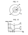
- FIG. 11 is an exemplary image of an iris 10c to describe the movement of pupil 10a and ANW 10b at a certain angle ⁇
- FIG. 12 is a graph illustrating an average pupillary radius R1, a pupillary radius R2 at a certain angle ⁇ , and a radius R3 of the ANW at a certain angle ⁇ , transformed in one dimensional data with the time variation.
- the first time 't1' represents the operation time of a flash light source
- the second time 't2' the starting time of contraction of R1
- the fifth time 't5' when the radius of the ANW is minimum at a certain angle ⁇ can be obtained through the reaction of the pupil and ANW reacting spontaneously to light.
- the invention utilizes a predetermined reference value considered representative of a living being if the movement of the pupillary radius exceeds a certain percentage (e.g. greater than 5 per cent) when the pupil is contracted.
- the pupillary edge also, must be detected from the captured iris dynamic image to observe the movement of the pupil.
- the iris image When the iris image is too lop-sided to identify, it can be captured again. Also, when other images are taken rather than the iris image, it is possible to discriminate between true images and false images in many cases.
- the domain(i) of definition which minimize the absolute value of function F(i) is at the center of the symmetry.
- the point on which the domains(i), minimizing the absolute value of function F(i), of definition intersect is set as the center of the symmetry. If the domains(i) of definition of the horizontal and vertical lines do not intersect, but are scattered, especially if they deviate from a predetermined range, this signifies that the captured image is not the iris image or the iris image is too biased to the right or left; hence, the iris image should be re-captured before proceeding with any further identification.
- the pupil and ANW are caused to contract and dilate by flash light source 12b.
- the movements of the pupil and ANW do not occur simultaneously and show different types according to each person.
- the parameters from the pupillary and ANW reaction (FIG. 11 and 12) obtained from the movements not taking place at the same time as such are used for the identification.
- a pupillogram or pupil histogram represents the average contraction and dilation of a pupil in response to a light flash at time T 0 .
- the vertical axis indicates the amplitude or radius of the pupil, while the horizontal axis indicates time beginning at T 0 or the time of the light flash.
- T L is the time at which the pupil begins contracting in response to the light flash;
- T L - T 0 is the pupil response latency time.
- a L is the average radius of the pupil prior to the light flash.
- T M is the time at which the pupil has contracted to the minimum radius, A m .
- the time for the pupil to contract, excluding the latency time, is T M - T L , or Tp.
- T 1 and T 2 are respectively the time of the 40th and 70th frame of the dynamic iris image and A 1 and A 2 are the corresponding radii of the pupil at times T 1 and T 2 .
- S P is the speed of the pupil contraction between T L and T M .
- D AB is the linear distance along the curve of pupil contraction between T L and T M .
- %A 1 is the ratio of the pupil dilation distance at T 1 , or A 1 -A m , to the average pupil contraction distance or A L -A m .
- %A 2 is the ratio of dilation distance at T 2 , or A 2 -A m , to the average pupil contraction distance or A L -A m .
- the pupillogram may be used to detect drug and/or alcohol use by individuals.
- the pupillogram of a person using drugs has a slower than normal time for the pupil to contract to the minimum radius. T M .
- the pupillogram of a person using alcohol is more flat in comparison to a non-alcohol using person, that is. D AB is smaller for the alcohol user. Also. %A 1 and %A 2 are smaller for the alcohol user.
- the value of parameters D AB , S P , T 2 -T 0 , T M , %A 1 and %A 2 for each pupil (left and right) are detected using a pupillogram.
- a ratio of values between the left and right eyes for each of these parameters is also computed.
- the detected and computed values are then compared to a normal, non-drug or alcohol using person's values; the normal person values are derived through experimentation. If the detected parameter values are much lower or smaller than the normal person values, then drug and/or alcohol use has been detected. If the detected parameter values approximately equal or exceed the normal person values, then drug and/or alcohol use has not been detected. This is because the pupil of a drug and/or alcohol using person reacts more slowly and contracts a smaller amount in comparison to a non-drug and/or alcohol using person.
- the ratio of the left and right pupil reaction of a person may be used to determine the presence of drugs and/or alcohol in the person's body.
- the ratios of the previously defined values D AB , S P , T 2 -T 0 , T M , %A 1 and %A 2 for the left and right pupil are compared after calculation as described above. If the ratios are much larger or smaller than 1:1 by more than approximately 15%, then drug and/or alcohol use has been detected. If the ratios are approximately 1:1, then drug and/or alcohol use has not been detected.
- a drug and/or alcohol using person has less coordination between the left and right pupillary reactions, thus a significant difference in the ratio of left and right pupil reaction is indicative of drug and/or alcohol use.
- An ANW and pupil shape confirmation process S 117-S119 then ascertains the user's identity by detecting the ANW and pupil out of the selected iris image, followed by determining the identification parameters according to the detected shape of the ANW and pupil.
- the ANW shape is uniquely determined in the present invention through the use of a Medial Axis Transform applied to the selected iris image signal.
- the pupil shape is uniquely determined in the present invention through the use of edge detection and curve fitting algorithms as known in the art.
- the ANW and pupil confirmation process can be comprised of the steps of detecting with step S 117 (FIGS. 10B and 10C) an ANW and pupil from the selected iris image signal; computing with step S118 the identification parameters based on the shape of the ANW by transforming the two dimensional image signal of the detected ANW with the Medial Axis Transform and the shape of the pupil by edge detection and curve fitting algorithms as described above; and confirming with steps S119. S120 the user's identity by searching the corresponding identification parameters from the database.
- FIG. 13 is an exemplary view of the ANW 10b and the lacuna 10d representing the edge detected from the iris image
- FIG. 14 is an exemplary view of the ANW 10b and the lacuna 10d showing the FIG. 13 in one dimensional data transformed by Medial Axis Transform.
- the Medial Axis Transform of the object having specific shape is the locus of the centers of the circles tangent to the boundary of the object at more than two points. In other words, it is the locus of the nearest points from the object boundary. Therefore, since it is possible to transform the two-dimensional object into the one-dimensional data with the Medial Axis Transform, this can be applied to identify an ANW shape, and the shape and position of a pupil.
- FIG. 18 is an exemplary view of the pupil and iris indicating shape, position, and identifying parameters.
- the shape of the pupil is uniquely determined in the present invention using an edge detection algorithm as known in the art.
- the pupil edge is generally indicated by reference character 10a in FIG. 18.
- the center of the iris and pupil respectively indicated by reference characters 10i and 10h on FIG. 18. are determined through geometry and used as identification parameters.
- the separation orientation and distance between the iris and pupil centers, generally indicated by reference character 10j, are used as identification parameters.
- the orientation and magnitude of the ellipticity of the pupil is uniquely determined in the present invention using curve and shape fitting algorithms as known in the art.
- the major and minor axes of the pupil ellipse are respectively indicated by reference characters 10m and 10n.
- the ellipticity of the pupil is expressed as the ratio of the minor axis 10n to the major axis 10m.
- Flat portions along the circumference of the pupil generally indicated by reference character 10f in FIG. 18, as well as areas where the pupil is drawn in or out, respectively 10g and 10e. can be recognized and characterized to enhance recognition quality as further identification parameters.
- a lacuna confirmation process S121-S127 is also used to ascertain the user's identity by judging whether the lacuna exists or not, detecting the lacuna zone if it exists, and then, determining the identification parameters on the basis of the detected location and shape of the lacuna.
- the lacuna confirmation process can be applicable to the above embodiments by including at least one of the following plurality of processes depicted in FIG. 10C: a first lacuna confirmation process S121, followed by steps S125-S129 to ascertain the user's identity by judging whether the lacuna exists based on the acquired iris selected still image, then transforming the image signal of the lacuna zone with Medial Axis Transform if the lacuna exists, and determining the identification parameters based on the location and shape of the lacuna out of the transformation result.
- a second lacuna confirmation process S122-S124 occurs as a result of the first lacuna confirmation process if the lacuna does not exist, wherein the user may be accepted if there is no lacuna in the reference iris after re-judging whether a lacuna exists in the reference iris; conversely, the user is rejected as improper if there exists a lacuna in the reference iris.
- the first lacuna confirmation process can be comprised of the steps of: judging with step S121 (FIG. 10C) whether a lacuna exists or not by detecting the edge of the iris image from the acquired still image signal of the iris; detecting with step S125 the lacuna zone, in case the lacuna exists as a result of the judging step; computing with step S126 the identification parameters on the basis of the shape and location of the lacuna after transforming a two-dimensional image signal of the detected lacuna zone with Medial Axis Transform; and confirming with steps S127-S129 the user's identity by searching the corresponding parameters from the database.
- the second lacuna confirmation process can be comprised of the steps of: judging with step S121 whether the lacuna exists or not on the input image; re-judging with step S122 whether the lacuna exists or not in the reference iris, in case the lacuna does not exist on the input image: accepting with step S123 if a lacuna does not exist in the reference iris, and rejecting with step S124 in case the lacuna exists in the reference iris.
- the card number is read or the user's PIN is inputted by keystroke through the card reading unit 40 or key input unit 50.
- the card number and PIN confirmation process is carried out to determine whether the corresponding number exists by searching the card number or the PIN through the data storage unit 80 in the control unit 70.
- the control unit 70 accepts the user as an identifiable user and then transmits the control signal to the motor driving unit 30 to adjust the camera height to be suitable for the user after reading the additional personal information corresponding to the card number or PIN.
- the control signal compares the height difference between the present camera position and the camera position appropriate to the user, and then adjusts the camera height automatically by driving the motor in a forward or reverse direction.
- the width between the two eyes can also be adjusted for each user.
- control unit 70 the adjustment of the initial auto-focusing is performed by lighting the infrared light source 12a by controlling the iris image pickup unit 20.
- the user is guided with the vision pointer 18 by switching on the vision guide light source 17 to prevent the iris image from biasing to one side.
- the guide light source 17 i.e., a thin blue light source
- the iris dynamic image is taken for a number of seconds while operating the flash light source 12b in a short cycle. All the light sources are then extinguished.
- the iris image should be taken such that it can illustrate the varying shape of the pupil and ANW via the flash light source 12b controlled by certain software for a short time. For this purpose, more than 25 frames per second of the iris image are taken in the invention.
- the successive images of the iris captured as described above are preprocessed in the data processing unit 60. Then, the image signal of the corresponding zone is selected after selecting the zone pertinent to the iris analysis.
- the analysis is performed on a sector by sector basis in accordance with the variable multisector system of spectral conversion described in detail above.
- the zone used to analyze the iris is the horizontal strip region, including the entire pupil, depicted in FIG. 8, i.e. the portion seen clearly since it is not affected by eyelashes, eyelids or the like of the person being identified.
- the control unit 70 performs the iris fiber structure confirmation process to ascertain the user's identity by using only selected low frequency components, as described in more detail above.
- the pupil and ANW reaction confirmation processes are performed to accept the captured image as representative of a living being if the contraction and dilation of the pupil and ANW are caused by the flash light source 12b, and to reject the captured image as not representative of a living being if there is no movement, after analyzing the reaction of the pupil and ANW from the iris dynamic image.
- control unit 70 which ascertains personal identity on the basis of the ANW and pupil shape by transforming the two dimensional image signal of the ANW zone having different characteristics in each person from the selected still iris image, with Medial Axis Transform (or Grass-Fire technique) as described above, into one dimensional data. Specific features of the pupil, as described above are also identified and compared.
- the first and second lacuna confirmation processes are then carried out with control unit 70, which lastly confirms a user's identity via the identification method of identifying whether a lacuna exists or not, and the location and shape of the lacuna if it exists.
- the lacuna is extracted from the selected iris still image in FIG. 13 and FIG. 14 through image treatment process: lacuna shape and location are used as identification parameters by representing the shape and location of a lacuna in one-dimensional data with the Medial Axis Transform when the lacuna shape is clearly seen through the edge detection.
- the present invention has numerous advantages in that it can prevent financial accidents when applied to banking systems and electronic transaction/settlement systems, and preclude security-related accidents when applied to access control systems, since the invention offers a method of distinguishing a particular person by identifying the iris of a living human, not counterfeited, quickly and accurately by determining a plurality of parameters for iris identification using the iris fiber structure and texture form, pupillary and ANW reaction in response to light, the shape of the ANW and pupil, the existence, shape, and location of a lacuna acquired from the iris dynamic image.
Landscapes
- Engineering & Computer Science (AREA)
- Health & Medical Sciences (AREA)
- General Health & Medical Sciences (AREA)
- Ophthalmology & Optometry (AREA)
- Human Computer Interaction (AREA)
- Physics & Mathematics (AREA)
- General Physics & Mathematics (AREA)
- Multimedia (AREA)
- Theoretical Computer Science (AREA)
- Measurement Of The Respiration, Hearing Ability, Form, And Blood Characteristics Of Living Organisms (AREA)
- Collating Specific Patterns (AREA)
Claims (36)
- System zum Überprüfen der Identität eines Lebewesens durch Irisabtastung, das Folgendes umfasst:a) eine Steuereinheit zum Empfangen von das Lebewesen identifizierenden Kennungsinformationen (40) und eine Datenspeichereinheit mit einer Datenbank, auf die die Steuereinheit zugreifen kann, zur Aufnahme vorbestimmter persönlicher Informationen in Verbindung mit einer identifizierbaren Person für einen Vergleich mit Kennungsinformationen;b) eine frisaufnahmeeinheit (20) mit einer Kamera, die von der Steuereinheit betätigt wird, wenn die Kennungsinformationen den vorbestimmten Formationen entsprechen, um Irisbilder zum Erzeugen von Eingangsbildsignalen zu erfassen; undc) eine Datenverarbeitungseinheit (60) zum Vorverarbeiten der Eingangsbildsignale zu verarbeiteten Daten, einschließlich des Identifizierens und Ausschließens von Sektoren des Irisbildes mit Interferenzen durch Vergleichen von Variationen von hochfrequenten Spektralkoeffizienten in benachbarten Sektoren;wobei die genannte Speichereinheit für das identifizierbare Wesen wenigstens einen von mehreren vorgespeicherten Parametern für eine Irisidentifikation beinhaltet, die aus der Gruppe ausgewählt ist, die sich wie folgt zusammensetzt: (1) Dichtigkeit und Texturform der Irisfaserstruktur unterteilt in eine Vielzahl von Sektoren, wobei für jeden Sektor eine Reihe von Frequenztransformationskoeffizienten berechnet werden, (2) Pupillenreaktion, (3) Form der Pupille, (4) autonome Nervenkranzreaktion, (5) Form des autonomen Nervenkranzes, (6) Existenz von Lakunen, (7) Ort von Lakunen und (8) Form von Lakunen, wobei die genannte Steuereinheit die Aufgabe hat, die verarbeiteten Daten mit dem/den genannten Parameter(n) zu vergleichen, um zu ermitteln, ob es eine eine Identitätsbestätigung anzeigende Übereinstimmung gibt und um ein gewähltes aus den Eingangsbildsignalen mit einem variablen Spektralkonversion-Multisektorsystem mit der Frequenztransformationsmethode zu analysieren.
- System nach Anspruch 1, wobei wenigstens ein ausgewähltes der Eingangsbildsignale mit einem variablen Spektralkonversion-Multisektorsystem mit Haar-Transformationsfunktionen analysiert wird.
- System nach Anspruch 2, wobei das Spektralkonversion-Multisektorsystem eine variable Auswahl von Sektoren der Iris ermöglicht, die für sichtbare Teile der Iris für Analysezwecke repräsentativ sind, die nicht durch Interferenzen verzerrt sind.
- System nach Anspruch 3, wobei es das genannte Spektralanalyse-Multisektorsystem ermöglicht, Defekte oder Interferenzen mit Rändern zu identifizieren und aus der Identifikationsanalyse auszuschließen.
- System nach Anspruch 4, wobei ein ausgewähltes der Iriseingangsbilder für die genannten Spektralanalysezwecke in einen äußeren Ring mit einem äußeren Rand, der sich etwa am Rand der Sklera-Iris befindet, und einen inneren kreisförmigen Teil unterteilt ist, der einwärts vom äußeren Ring beabstandet ist, und mit einem Radius, der um eine vorbestimmte Distanz vom äußeren Rand einwärts beabstandet ist.
- System nach Anspruch 5, wobei die genannte vorbestimmte Distanz etwa 30-80 Pixel beträgt.
- System nach Anspruch 6, wobei der äußere Ring und ein Bereich innerhalb der kreisförmigen Zone zwischen dem Rand der kreisförmigen Zone zum äußeren Ring und der Peripherie der Pupille jeweils in eine Mehrzahl von Sektoren (n) und (p) unterteilt sind, wobei n derselbe oder ein anderer Wert ist als p, so dass insgesamt n + p Sektoren entstehen, wobei eine vorbestimmte Anzahl (m2) von Haar-Koeffizienten mit einer eine m x m Matrix bildenden Haar-Transformation berechnet werden.
- System nach Anspruch 7, wobei n=16, p=16 und m=32 ist und für jeden der genannten 32 Sektoren 1024 Haar-Funktionskoeffizienten mit einer Haar-Transformation und von einer 32 x 32 Matrix berechnet werden.
- System nach Anspruch 8, wobei Sektoren, die durch Augenlider, Augenwimpern und dergleichen verdeckt oder gestört werden, durch einen Haar-Koeffizientenvergleich im Nachbarsektor verworfen werden.
- System nach Anspruch 7, wobei durch Vergleichen von Nachbarsektor-Haar-Koeffizienten ein Sektor bei der Analyse als mangelhaft verworfen wird, wenn eine vorbestimmte starke Variation von Hochfrequenzkoeffizienten erkannt wird.
- System nach Anspruch 10, wobei nach der Beseitigung verworfener Sektoren aus der Analyse eine Teilmenge eines vollständigen Satzes von m2 Haar-Koeffizienten ausgewählt wird, um eine vorbestimmte Anzahl von Koeffizienten von der m x m Matrix von für Analysezwecke ausgewählten m2 Haar-Koeffizienten zu erzeugen.
- System nach Anspruch 11, wobei m = 32 ist und die genannte Teilmenge 31 Koeffizienten beinhaltet, die aus der 32 x 32 Matrix von Haar-Koeffizienten ausgewählt wurden.
- System nach Anspruch 11, wobei die Auswahl der vorbestimmten Anzahl von Koeffizienten zum Erzeugen eines Irisreferenzwortes verwendet wird.
- System nach Anspruch 13, wobei die genannte vorbestimmte Anzahl von Koeffizienten für eine gewählte Niederfrequenzzone repräsentativ ist, die für Identifikationszwecke verwendet wird.
- System nach Anspruch 1, wobei die genannte Steuereinheit Informationen berechnet, die für eine Papillarreaktion repräsentativ ist, durch Verwenden der Eingangsbildsignale zum Erzeugen eines Pupillenhistogramms oder Pupillogramms, das für die durchschnittliche Verkleinerung und Erweiterung einer Pupille im Laufe der zeit als Reaktion auf Lichtreize repräsentativ ist.
- System nach Anspruch 15, wobei das genannte Pupillogramm eine Bildabtastung eines lebenden Lebewesens bestätigt.
- System nach Anspruch 1, wobei die verarbeiteten Daten die Form der Pupille beinhalten, die mit einem Kurvenanpassungsund/oder einem Randerkennungsalgorithmus ermittelt wurde.
- System nach Anspruch 17, wobei die verarbeiteten Daten die Elliptizität der Pupille und die Orientierung der Ellipsenhauptachse beinhalten.
- System nach Anspruch 17, wobei flache Abschnitte ggf. entlang der Peripherie der Pupille für Identifikationszwecke erkannt werden.
- System nach Anspruch 1, wobei Niederfrequenzkomponenten von zweidimensionalen Haar-Transformationskoeffizienten für Identifikationszwecke aus einem ausgewählten der Eingangsbildsignale erhalten werden.
- System nach Anspruch 1, wobei die genannte Irisbild-Aufnahmeeinheit ferner eine Sichtführungseinheit zum Ausrichten des Auges des Benutzers auf die Kameralinse umfasst.
- Verfahren zum Überprüfen der Identität eines Lebewesens, das die folgenden Schritte beinhaltet:a) anfängliches Ermitteln, ob das Lebewesen eine Identität hat, die einem in einer Datenbank identifizierten Lebewesen entspricht;b) wenn die Antwort auf Schritt (a) ja ist, Einholen mehrerer Bilder, die für wenigstens einen Teil der Iris und die Pupille des Auges des Lebewesens repräsentativ sind;c) Verarbeiten der genannten Mehrzahl von Bildern einschließlich des Identifizierens und Ausschließens von Sektoren des Irisbildes mit Interferenz durch Vergleichen von Variationen von hochfrequenten Spektralkoeffizienten in Nachbarsektoren, um Irisidentifikationsparameter-Informationen zu erhalten, die ausgewählt sind aus der Gruppe, die sich wie folgt zusammensetzt: (1) Dichtigkeit und/oder Texturform der Irisfaserstruktur unterteilt in eine Vielzahl von Sektoren, wobei für jeden Sektor eine Reihe von Funktionskoeffizienten von Frequenztransformationen berechnet werden, (2) Pupillenreaktion, (3) Form der Pupille, (4) autonome Nervenkranzreaktion, (5) Form des autonomen Nervenkranzes, (6) Existenz von Lakunen, (7) Ort der Lakunen und (8) Form der Lakunen;d) Vergleichen vorbestimmter Charakteristiken der genannten zuvor erhaltenen Irisidentifikationsinformationen mit den genannten in Schritt (c) erhaltenen Irisidentifikationsinformationen mittels eines variablen Spektralanalysen-Multisektorsystems, um es zuzulassen, dass eine variable Auswahl von für sichtbare Teile der Iris repräsentativen Sektoren der Iris für Analysezwecke erfolgt, die nicht durch Interferenzen verzerrt werden; unde) Prüfen, ob es eine Übereinstimmungsanzeige von in Schritt d) verglichenen Daten gibt.
- Verfahren nach Anspruch 22, das ferner den Schritt des Verwendens des genannten variablen Spektralanalyse-Multisektorsystems beinhaltet, um Defekte oder Interferenzen mit zu identifizierenden Rändern aus der Identifikationsanalyse auszuschließen.
- Verfahren nach Anspruch 22, wobei der Verarbeitungsschritt das Unterteilen des Irisbildes in eine vorbestimmte Anzahl von Sektoren beinhaltet, die sich in einem äußeren Ring und einem kreisförmigen Bereich befinden, der konzentrisch zu dem genannten äußeren Ring ausgebildet ist und die Pupille beinhaltet.
- Verfahren nach Anspruch 24, wobei die genannten Sektoren auf einem Sektor auf Nachbarsektorbasis analysiert werden und bestimmte Sektoren als defekt verworfen werden, wenn eine vorbestimmte starke Variation von Hochfrequenzkoeffizienten erfasst wird.
- Verfahren nach Anspruch 25, wobei der Verarbeitungsschritt nach dem Beseitigen von verworfenen Sektoren das Ermitteln einer Teilmenge einer kompletten vorbestimmten Anzahl von Koeffizienten beinhaltet, die für Analysezwecke ausgewählt werden, und die Auswahl der vorbestimmten Anzahl von Koeffizienten in der Teilmenge für jeden gewählten Sektor zum Erzeugen eines Irisreferenzdatensatzes verwendet wird, der im Vergleichsschritt (d) von Anspruch 22 verwendet wird.
- verfahren nach Anspruch 26, wobei Koeffizienten, die für eine gewählte Frequenzzone von gewählten Sektoren repräsentativ sind, für Identifikationszwecke verwendet werden.
- Verfahren nach Anspruch 22, das den weiteren Schritt des Einholens der genannten Mehrzahl von Bildern für jedes Auge beinhaltet.
- Verfahren nach Anspruch 22, das den weiteren schritt des Einleitens von Schritt (b) von Anspruch 22 durch vergleichen von eingegebenen Passwortinformationen mit zuvor gespeicherten Informationen über eine identifizierbare Person beinhaltet.
- Verfahren nach Anspruch 22, das den weiteren Schritt des Beleuchtens des Auges mit einer Lichtquelle beinhaltet, gefolgt vom Erfassen, in Folge, einer Mehrzahl der genannten Irisbilder.
- Verfahren nach Anspruch 22, wobei der Verarbeitungsschritt das Analysieren der Form der Irispupille unter Verwendung eines Kurvenanpassungs- und/oder Randerkennungsalgorithmus beinhaltet.
- Verfahren nach Anspruch 31, wobei der Verarbeitungsschritt das Erfassen der Elliptizität der Pupille und der Ausrichtung der Ellipsenhauptachse beinhaltet.
- Verfahren nach Anspruch 32, wobei der Verarbeitungsschritt das Ermitteln der Existenz von flachen Abschnitten entlang der Peripherie der Pupille nutzt.
- Verfahren nach Anspruch 22, wobei der Verarbeitungsschritt das Einholen von Niederfrequenzkomponenten von zweidimensionalen Haar-Transformationskoeffizienten aus einem ausgewählten einen der Eingangsbildsignale beinhaltet.
- Verfahren nach Anspruch 22, wobei der Verarbeitungsschritt das Auswählen der Haar-Transformation aus einer Klasse von Signum-Haar-Funktionen beinhaltet.
- verfahren nach Anspruch 22, das den weiteren Schritt des Nutzens von zuvor gespeicherten Informationen beinhaltet, um das Auge automatisch auf eine Quelle zum Einholen der genannten Mehrzahl von Bildern in Schritt (b) auszurichten.
Applications Claiming Priority (7)
| Application Number | Priority Date | Filing Date | Title |
|---|---|---|---|
| KR9912440 | 1999-04-09 | ||
| KR9912438 | 1999-04-09 | ||
| KR1019990012438A KR100356600B1 (ko) | 1999-04-09 | 1999-04-09 | 열공 및/또는 자율신경환의 형태에 의한 홍채인식방법 |
| KR19990012439 | 1999-04-09 | ||
| KR9912439 | 1999-04-09 | ||
| KR19990012440 | 1999-04-09 | ||
| PCT/KR2000/000324 WO2000062239A1 (en) | 1999-04-09 | 2000-04-07 | Iris identification system and method of identifying a person through iris recognition |
Publications (3)
| Publication Number | Publication Date |
|---|---|
| EP1093633A1 EP1093633A1 (de) | 2001-04-25 |
| EP1093633A4 EP1093633A4 (de) | 2004-10-20 |
| EP1093633B1 true EP1093633B1 (de) | 2007-09-12 |
Family
ID=27349933
Family Applications (1)
| Application Number | Title | Priority Date | Filing Date |
|---|---|---|---|
| EP00921118A Expired - Lifetime EP1093633B1 (de) | 1999-04-09 | 2000-04-07 | Irisindentifikationssystem und verfahren zum identifizieren einer person durch iris-erkennung |
Country Status (11)
| Country | Link |
|---|---|
| US (1) | US6247813B1 (de) |
| EP (1) | EP1093633B1 (de) |
| CN (1) | CN100347718C (de) |
| AT (1) | ATE373280T1 (de) |
| AU (1) | AU6408600A (de) |
| DE (1) | DE60036347T2 (de) |
| DK (1) | DK1093633T3 (de) |
| ES (1) | ES2292437T3 (de) |
| PT (1) | PT1093633E (de) |
| TW (1) | TW555547B (de) |
| WO (1) | WO2000062239A1 (de) |
Cited By (1)
| Publication number | Priority date | Publication date | Assignee | Title |
|---|---|---|---|---|
| US10469889B2 (en) | 2011-04-11 | 2019-11-05 | Nec Corporation | Information distribution device, information reception device, system, program, and method |
Families Citing this family (169)
| Publication number | Priority date | Publication date | Assignee | Title |
|---|---|---|---|---|
| USRE39539E1 (en) | 1996-08-19 | 2007-04-03 | Torch William C | System and method for monitoring eye movement |
| GB9907515D0 (en) * | 1999-04-01 | 1999-05-26 | Ncr Int Inc | Self service terminal |
| US6700998B1 (en) * | 1999-04-23 | 2004-03-02 | Oki Electric Industry Co, Ltd. | Iris registration unit |
| JP2001034754A (ja) * | 1999-07-19 | 2001-02-09 | Sony Corp | 虹彩認証装置 |
| US7277561B2 (en) * | 2000-10-07 | 2007-10-02 | Qritek Co., Ltd. | Iris identification |
| DE10052201B8 (de) * | 2000-10-20 | 2005-06-30 | Carl Zeiss Meditec Ag | Verfahren und Vorrichtung zur Identifizierung eines Patienten und eines Operationsgebietes |
| US7215797B2 (en) * | 2001-02-02 | 2007-05-08 | Lg Electronics Inc. | Iris recognition system |
| JP3586431B2 (ja) * | 2001-02-28 | 2004-11-10 | 松下電器産業株式会社 | 個人認証方法および装置 |
| KR100374707B1 (ko) * | 2001-03-06 | 2003-03-04 | 에버미디어 주식회사 | 도비치스 웨이블렛 변환을 이용한 홍채인식방법 |
| DE60135879D1 (de) * | 2001-04-27 | 2008-10-30 | Bausch & Lomb | Iris-mustererkennung und ausrichtung |
| JP2003141516A (ja) * | 2001-10-31 | 2003-05-16 | Matsushita Electric Ind Co Ltd | 虹彩撮像装置及び虹彩認証装置 |
| KR100453943B1 (ko) * | 2001-12-03 | 2004-10-20 | 주식회사 세넥스테크놀로지 | 개인 식별을 위한 홍채 영상의 처리 및 인식방법과 시스템 |
| KR20030051970A (ko) * | 2001-12-20 | 2003-06-26 | 주식회사 큐리텍 | 홍채 등록 및 인식 시스템 |
| AU2003235641A1 (en) * | 2002-01-16 | 2003-07-30 | Iritech, Inc. | System and method for iris identification using stereoscopic face recognition |
| US6665426B1 (en) * | 2002-01-29 | 2003-12-16 | West Virginia University Research Corporation | Method of biometric identification of an individual and associated apparatus |
| US7155035B2 (en) | 2002-02-05 | 2006-12-26 | Matsushita Electric Industrial Co., Ltd. | Personal authentication method, personal authentication apparatus and image capturing device |
| US7039224B2 (en) * | 2002-04-29 | 2006-05-02 | Activcard Ireland Limited | Method and device for preventing false acceptance of latent fingerprint images |
| AUPS254302A0 (en) * | 2002-05-24 | 2002-06-13 | Resmed Limited | A sleepiness test |
| KR20040026905A (ko) * | 2002-09-26 | 2004-04-01 | 주식회사 세넥스테크놀로지 | 실시간 홍채인식을 위한 영상품질 평가장치 및 방법과 그프로그램을 저장한 기록매체 |
| CN100337248C (zh) * | 2002-11-07 | 2007-09-12 | 松下电器产业株式会社 | 个人认证方法和认证程序、虹膜登录装置和认证装置 |
| US7436986B2 (en) * | 2003-03-25 | 2008-10-14 | Bausch & Lomb Incorporated | Positive patient identification |
| US7599524B2 (en) * | 2003-04-04 | 2009-10-06 | Sarnoff Corporation | Method and apparatus for providing a robust object finder |
| WO2004097743A1 (ja) * | 2003-04-28 | 2004-11-11 | Matsushita Electric Industrial Co. Ltd. | 偽眼識別方法および装置、偽眼識別プログラム、虹彩認証方法、偽造印刷物識別方法、並びに画像識別方法 |
| US8049812B2 (en) | 2006-03-03 | 2011-11-01 | Honeywell International Inc. | Camera with auto focus capability |
| US8442276B2 (en) | 2006-03-03 | 2013-05-14 | Honeywell International Inc. | Invariant radial iris segmentation |
| US8098901B2 (en) | 2005-01-26 | 2012-01-17 | Honeywell International Inc. | Standoff iris recognition system |
| US7593550B2 (en) | 2005-01-26 | 2009-09-22 | Honeywell International Inc. | Distance iris recognition |
| US8090157B2 (en) | 2005-01-26 | 2012-01-03 | Honeywell International Inc. | Approaches and apparatus for eye detection in a digital image |
| US8045764B2 (en) | 2005-01-26 | 2011-10-25 | Honeywell International Inc. | Expedient encoding system |
| US8064647B2 (en) | 2006-03-03 | 2011-11-22 | Honeywell International Inc. | System for iris detection tracking and recognition at a distance |
| US8705808B2 (en) | 2003-09-05 | 2014-04-22 | Honeywell International Inc. | Combined face and iris recognition system |
| US7731360B2 (en) * | 2003-11-07 | 2010-06-08 | Neuro Kinetics | Portable video oculography system |
| US20050111704A1 (en) * | 2003-11-24 | 2005-05-26 | Verghis James S. | Iris mapping and compatibility and personality evaluation |
| FR2864290B1 (fr) * | 2003-12-18 | 2006-05-26 | Sagem | Procede et dispositif de reconnaissance d'iris |
| JP2005258860A (ja) * | 2004-03-12 | 2005-09-22 | Matsushita Electric Ind Co Ltd | 複数認証方法及びその装置 |
| US20110077548A1 (en) * | 2004-04-01 | 2011-03-31 | Torch William C | Biosensors, communicators, and controllers monitoring eye movement and methods for using them |
| US10039445B1 (en) | 2004-04-01 | 2018-08-07 | Google Llc | Biosensors, communicators, and controllers monitoring eye movement and methods for using them |
| CA2561287C (en) * | 2004-04-01 | 2017-07-11 | William C. Torch | Biosensors, communicators, and controllers monitoring eye movement and methods for using them |
| GB0412175D0 (en) * | 2004-06-01 | 2004-06-30 | Smart Sensors Ltd | Identification of image characteristics |
| US20050281440A1 (en) * | 2004-06-18 | 2005-12-22 | Pemer Frederick A | Iris feature detection and sensor-based edge detection |
| US8333472B2 (en) * | 2004-07-13 | 2012-12-18 | Neuro Kinetics | Compact neuro-otologic, neuro-ophthalmologic testing device and dynamic visual acuity testing and desensitization platform |
| IL165586A0 (en) * | 2004-12-06 | 2006-01-15 | Daphna Palti Wasserman | Multivariate dynamic biometrics system |
| FR2880136B1 (fr) * | 2004-12-29 | 2007-03-02 | Sagem | Procede de verification de la validite d'un oeil |
| JP4449762B2 (ja) * | 2005-01-24 | 2010-04-14 | コニカミノルタビジネステクノロジーズ株式会社 | 人物照合装置、人物照合システム及び人物照合方法 |
| JP2006202212A (ja) * | 2005-01-24 | 2006-08-03 | Konica Minolta Business Technologies Inc | 個人認証装置、情報処理装置及び個人認証システム |
| KR101224408B1 (ko) * | 2005-01-26 | 2013-01-22 | 허니웰 인터내셔널 인코포레이티드 | 원격 홍채 인식 시스템 |
| US20060165264A1 (en) * | 2005-01-26 | 2006-07-27 | Hirofumi Saitoh | Method and apparatus for acquiring images, and verification method and verification apparatus |
| WO2006081505A1 (en) | 2005-01-26 | 2006-08-03 | Honeywell International Inc. | A distance iris recognition system |
| KR100658426B1 (ko) * | 2005-01-31 | 2006-12-15 | 김신호 | 리니어모터 구동에 의한 홍채줌카메라 촬영장치 |
| US7769218B2 (en) * | 2005-03-23 | 2010-08-03 | Apteryx, Inc. | System and method to adjust medical imaging equipment |
| US7760962B2 (en) * | 2005-03-30 | 2010-07-20 | Casio Computer Co., Ltd. | Image capture apparatus which synthesizes a plurality of images obtained by shooting a subject from different directions, to produce an image in which the influence of glare from a light is reduced |
| US7327860B2 (en) * | 2005-05-04 | 2008-02-05 | West Virginia University | Conjunctival scans for personal identification |
| GB0512729D0 (en) * | 2005-06-22 | 2005-07-27 | Ecebs Group Ltd | Smartcard indexed pupil response test |
| US8260008B2 (en) | 2005-11-11 | 2012-09-04 | Eyelock, Inc. | Methods for performing biometric recognition of a human eye and corroboration of same |
| US7801335B2 (en) * | 2005-11-11 | 2010-09-21 | Global Rainmakers Inc. | Apparatus and methods for detecting the presence of a human eye |
| WO2008016724A2 (en) | 2006-03-03 | 2008-02-07 | Honeywell International, Inc. | An iris recognition system having image quality metrics |
| WO2007103834A1 (en) | 2006-03-03 | 2007-09-13 | Honeywell International, Inc. | Indexing and database search system |
| US8364646B2 (en) | 2006-03-03 | 2013-01-29 | Eyelock, Inc. | Scalable searching of biometric databases using dynamic selection of data subsets |
| GB2450024B (en) | 2006-03-03 | 2011-07-27 | Honeywell Int Inc | Modular biometrics collection system architecture |
| KR101423153B1 (ko) | 2006-03-03 | 2014-07-25 | 허니웰 인터내셔널 인코포레이티드 | 불변 방사상 홍채 세그먼트화 |
| AU2007220010B2 (en) | 2006-03-03 | 2011-02-17 | Gentex Corporation | Single lens splitter camera |
| DE102006021002A1 (de) * | 2006-05-04 | 2007-11-08 | Henning, Jürgen, Dipl.-Ing. | Verfahren zur Verifizierung und Identifizierung von Personen |
| US8014571B2 (en) * | 2006-05-15 | 2011-09-06 | Identix Incorporated | Multimodal ocular biometric system |
| US8604901B2 (en) * | 2006-06-27 | 2013-12-10 | Eyelock, Inc. | Ensuring the provenance of passengers at a transportation facility |
| WO2008033784A2 (en) * | 2006-09-15 | 2008-03-20 | Retica Systems, Inc. | Long distance multimodal biometric system and method |
| US8121356B2 (en) | 2006-09-15 | 2012-02-21 | Identix Incorporated | Long distance multimodal biometric system and method |
| WO2008091401A2 (en) | 2006-09-15 | 2008-07-31 | Retica Systems, Inc | Multimodal ocular biometric system and methods |
| EP2076871A4 (de) | 2006-09-22 | 2015-09-16 | Eyelock Inc | Kompaktes biometrisches erfassungssystem und entsprechendes verfahren |
| US7970179B2 (en) * | 2006-09-25 | 2011-06-28 | Identix Incorporated | Iris data extraction |
| WO2008042879A1 (en) | 2006-10-02 | 2008-04-10 | Global Rainmakers, Inc. | Fraud resistant biometric financial transaction system and method |
| US7809747B2 (en) * | 2006-10-23 | 2010-10-05 | Donald Martin Monro | Fuzzy database matching |
| US9846739B2 (en) | 2006-10-23 | 2017-12-19 | Fotonation Limited | Fast database matching |
| US7769219B2 (en) * | 2006-12-11 | 2010-08-03 | Cytyc Corporation | Method for assessing image focus quality |
| US7621636B2 (en) * | 2007-01-10 | 2009-11-24 | Clarity Medical Systems, Inc. | Working distance and alignment sensor for a fundus camera |
| RU2326589C1 (ru) * | 2007-01-15 | 2008-06-20 | Дмитрий Евгеньевич Антонов | Способ идентификации личности по радужной оболочке глаза (его варианты) |
| WO2008131201A1 (en) | 2007-04-19 | 2008-10-30 | Global Rainmakers, Inc. | Method and system for biometric recognition |
| US8953849B2 (en) | 2007-04-19 | 2015-02-10 | Eyelock, Inc. | Method and system for biometric recognition |
| US8063889B2 (en) | 2007-04-25 | 2011-11-22 | Honeywell International Inc. | Biometric data collection system |
| US8031970B2 (en) * | 2007-08-27 | 2011-10-04 | Arcsoft, Inc. | Method of restoring closed-eye portrait photo |
| US20090060348A1 (en) * | 2007-08-28 | 2009-03-05 | Donald Martin Monro | Determination of Image Similarity |
| US9117119B2 (en) | 2007-09-01 | 2015-08-25 | Eyelock, Inc. | Mobile identity platform |
| US9036871B2 (en) | 2007-09-01 | 2015-05-19 | Eyelock, Inc. | Mobility identity platform |
| US8212870B2 (en) | 2007-09-01 | 2012-07-03 | Hanna Keith J | Mirror system and method for acquiring biometric data |
| US8553948B2 (en) | 2007-09-01 | 2013-10-08 | Eyelock, Inc. | System and method for iris data acquisition for biometric identification |
| US9002073B2 (en) | 2007-09-01 | 2015-04-07 | Eyelock, Inc. | Mobile identity platform |
| US7824034B2 (en) * | 2007-09-19 | 2010-11-02 | Utc Fire & Security Americas Corporation, Inc. | Iris imaging system and method for the same |
| US8189879B2 (en) | 2008-02-14 | 2012-05-29 | Iristrac, Llc | System and method for animal identification using IRIS images |
| US9655515B2 (en) * | 2008-04-08 | 2017-05-23 | Neuro Kinetics | Method of precision eye-tracking through use of iris edge based landmarks in eye geometry |
| US8436907B2 (en) | 2008-05-09 | 2013-05-07 | Honeywell International Inc. | Heterogeneous video capturing system |
| WO2009158662A2 (en) | 2008-06-26 | 2009-12-30 | Global Rainmakers, Inc. | Method of reducing visibility of illimination while acquiring high quality imagery |
| US8213782B2 (en) | 2008-08-07 | 2012-07-03 | Honeywell International Inc. | Predictive autofocusing system |
| US8090246B2 (en) | 2008-08-08 | 2012-01-03 | Honeywell International Inc. | Image acquisition system |
| US8306279B2 (en) * | 2008-09-15 | 2012-11-06 | Eyelock, Inc. | Operator interface for face and iris recognition devices |
| US10398309B2 (en) | 2008-10-09 | 2019-09-03 | Neuro Kinetics, Inc. | Noninvasive rapid screening of mild traumatic brain injury using combination of subject's objective oculomotor, vestibular and reaction time analytic variables |
| US9039631B2 (en) | 2008-10-09 | 2015-05-26 | Neuro Kinetics | Quantitative, non-invasive, clinical diagnosis of traumatic brain injury using VOG device for neurologic testing |
| US8585609B2 (en) * | 2008-10-09 | 2013-11-19 | Neuro Kinetics, Inc. | Quantitative, non-invasive, clinical diagnosis of traumatic brain injury using simulated distance visual stimulus device for neurologic testing |
| US20100278394A1 (en) * | 2008-10-29 | 2010-11-04 | Raguin Daniel H | Apparatus for Iris Capture |
| US8317325B2 (en) * | 2008-10-31 | 2012-11-27 | Cross Match Technologies, Inc. | Apparatus and method for two eye imaging for iris identification |
| US8280119B2 (en) | 2008-12-05 | 2012-10-02 | Honeywell International Inc. | Iris recognition system using quality metrics |
| TWI392858B (zh) * | 2008-12-12 | 2013-04-11 | Inst Information Industry | Pupil position acquisition system, method and computer program products |
| JP5126084B2 (ja) * | 2009-01-22 | 2013-01-23 | 日本電気株式会社 | 生体認証装置、生体認証方法及びプログラム |
| US8374404B2 (en) * | 2009-02-13 | 2013-02-12 | Raytheon Company | Iris recognition using hyper-spectral signatures |
| US8195044B2 (en) | 2009-03-30 | 2012-06-05 | Eyelock Inc. | Biometric camera mount system |
| US8630464B2 (en) | 2009-06-15 | 2014-01-14 | Honeywell International Inc. | Adaptive iris matching using database indexing |
| US8472681B2 (en) | 2009-06-15 | 2013-06-25 | Honeywell International Inc. | Iris and ocular recognition system using trace transforms |
| JP2011008713A (ja) * | 2009-06-29 | 2011-01-13 | Fujitsu Semiconductor Ltd | 画像処理プログラム、画像処理装置、および画像処理方法 |
| DE102009039190A1 (de) | 2009-08-28 | 2011-03-03 | Human Bios Gmbh | Verfahren für die Zugriffskontrolle oder Autorisierung einer Handlung |
| US10216995B2 (en) | 2009-09-25 | 2019-02-26 | International Business Machines Corporation | System and method for generating and employing short length iris codes |
| US8452131B2 (en) * | 2009-09-25 | 2013-05-28 | International Business Machines Corporation | Iris recognition system and method |
| US20110119141A1 (en) * | 2009-11-16 | 2011-05-19 | Hoyos Corporation | Siccolla Identity Verification Architecture and Tool |
| US20110142297A1 (en) * | 2009-12-16 | 2011-06-16 | Eye Controls, Llc | Camera Angle Compensation in Iris Identification |
| US8890946B2 (en) * | 2010-03-01 | 2014-11-18 | Eyefluence, Inc. | Systems and methods for spatially controlled scene illumination |
| US8577094B2 (en) | 2010-04-09 | 2013-11-05 | Donald Martin Monro | Image template masking |
| TWI466038B (zh) * | 2010-06-02 | 2014-12-21 | Nat Univ Chin Yi Technology | Eyelid length measurement method and device thereof |
| US8742887B2 (en) | 2010-09-03 | 2014-06-03 | Honeywell International Inc. | Biometric visitor check system |
| US10043229B2 (en) | 2011-01-26 | 2018-08-07 | Eyelock Llc | Method for confirming the identity of an individual while shielding that individual's personal data |
| RU2589859C2 (ru) | 2011-02-17 | 2016-07-10 | АЙЛОК ЭлЭлСи | Эффективный способ и система для получения данных изображения сцены и изображения радужной оболочки с использованием одного датчика |
| US20120268241A1 (en) | 2011-04-19 | 2012-10-25 | Eyelock Inc. | Biometric chain of provenance |
| WO2012158825A2 (en) * | 2011-05-17 | 2012-11-22 | Eyelock Inc. | Systems and methods for illuminating an iris with visible light for biometric acquisition |
| US8385685B2 (en) * | 2011-06-08 | 2013-02-26 | Honeywell International Inc. | System and method for ocular recognition |
| CN102429637B (zh) * | 2011-08-17 | 2015-09-16 | 北京百纳威尔科技有限公司 | 移动终端虹膜检测装置 |
| RU2623795C2 (ru) | 2011-08-22 | 2017-06-29 | АЙЛОК ЭлЭлСи | Системы и способы для захвата безартефактных изображений |
| CN104780828B (zh) * | 2012-03-26 | 2017-10-27 | 纽约大学 | 用于评估中枢神经系统完整性的方法和试剂盒 |
| US9122926B2 (en) * | 2012-07-19 | 2015-09-01 | Honeywell International Inc. | Iris recognition using localized Zernike moments |
| US8808179B1 (en) | 2012-08-06 | 2014-08-19 | James Z. Cinberg | Method and associated apparatus for detecting minor traumatic brain injury |
| KR101417415B1 (ko) * | 2012-11-19 | 2014-07-08 | 아이리텍 잉크 | 살아있는 눈 식별 방법 및 장치 |
| EP2948040B1 (de) * | 2013-01-28 | 2023-06-07 | LKC Technologies, Inc. | Visuelle elektrophysiologische vorrichtung |
| US9495526B2 (en) | 2013-03-15 | 2016-11-15 | Eyelock Llc | Efficient prevention of fraud |
| EP3087533A4 (de) | 2013-12-23 | 2017-09-20 | Eyelock Llc | Verfahren und vorrichtung für leistungseffiziente iriserkennung |
| CN105981047A (zh) | 2014-01-06 | 2016-09-28 | 眼锁有限责任公司 | 用于重复虹膜识别的方法和设备 |
| US9355315B2 (en) * | 2014-07-24 | 2016-05-31 | Microsoft Technology Licensing, Llc | Pupil detection |
| AU2015301370B2 (en) | 2014-08-04 | 2020-04-30 | New York University | Methods and kits for diagnosing, assessing or quantitating drug use, drug abuse and narcosis, internuclear ophthalmoplegia, attention deficit hyperactivity disorder (ADHD), chronic traumatic encephalopathy, schizophrenia spectrum disorders and alcohol consumption |
| EP3192009A4 (de) | 2014-09-12 | 2018-04-25 | Eyelock Llc | Verfahren und vorrichtung zum richten des blicks eines benutzers in einem iriserkennungssystem |
| WO2016049273A1 (en) | 2014-09-24 | 2016-03-31 | Sri International | Control of wireless communication device capability in a mobile device with a biometric key |
| US10332113B2 (en) | 2014-11-19 | 2019-06-25 | Eyelock Llc | Model-based prediction of an optimal convenience metric for authorizing transactions |
| KR20170092545A (ko) | 2014-12-03 | 2017-08-11 | 프린스톤 아이덴티티, 인크. | 모바일 디바이스 생체측정 애드-온을 위한 시스템 및 방법 |
| US10074011B2 (en) | 2015-01-20 | 2018-09-11 | Eyelock Llc | Lens system for high quality visible image acquisition and infra-red iris image acquisition |
| EP3067459A1 (de) | 2015-03-09 | 2016-09-14 | LG Electronics Inc. | Trocknungsmaschine |
| KR102306539B1 (ko) | 2015-03-12 | 2021-09-29 | 삼성전자주식회사 | 홍채를 촬영하기 위하여 이용되는 광을 조사하는 방법 및 디바이스 |
| CN107580767B (zh) | 2015-03-12 | 2020-12-29 | 眼锁有限责任公司 | 使用生物特征来管理网络活动的方法和系统 |
| WO2016168814A1 (en) * | 2015-04-16 | 2016-10-20 | Tobii Ab | Identification and/or authentication of a user using gaze information |
| KR102393228B1 (ko) * | 2015-05-11 | 2022-04-29 | 매직 립, 인코포레이티드 | 뉴럴 네트워크들을 활용하여 생체 인증 사용자 인식을 위한 디바이스들, 방법들 및 시스템들 |
| CN105631394B (zh) * | 2015-05-29 | 2019-08-02 | 宇龙计算机通信科技(深圳)有限公司 | 虹膜信息采集方法、虹膜信息采集装置及终端 |
| US10157312B2 (en) * | 2015-10-08 | 2018-12-18 | Microsoft Technology Licensing, Llc | Iris recognition |
| US10311299B2 (en) | 2015-12-21 | 2019-06-04 | Eyelock Llc | Reflected optic camera module for iris recognition in a computing device |
| JP2019506694A (ja) | 2016-01-12 | 2019-03-07 | プリンストン・アイデンティティー・インコーポレーテッド | 生体測定分析のシステムおよび方法 |
| CA3016189A1 (en) | 2016-03-07 | 2017-09-14 | Magic Leap, Inc. | Blue light adjustment for biometric security |
| WO2017173228A1 (en) | 2016-03-31 | 2017-10-05 | Princeton Identity, Inc. | Biometric enrollment systems and methods |
| WO2017172695A1 (en) | 2016-03-31 | 2017-10-05 | Princeton Identity, Inc. | Systems and methods of biometric anaysis with adaptive trigger |
| WO2017201147A2 (en) | 2016-05-18 | 2017-11-23 | Eyelock, Llc | Iris recognition methods and systems based on an iris stochastic texture model |
| CN106339668A (zh) * | 2016-08-16 | 2017-01-18 | 信利光电股份有限公司 | 一种虹膜识别方法及虹膜识别系统 |
| CN106899567B (zh) | 2016-08-24 | 2019-12-13 | 阿里巴巴集团控股有限公司 | 用户核身方法、装置及系统 |
| WO2018156726A1 (en) | 2017-02-24 | 2018-08-30 | Eyelock, Llc | Systems and methods for providing illumination for iris biometric acquisition |
| US11531756B1 (en) | 2017-03-20 | 2022-12-20 | Hid Global Corporation | Apparatus for directing presentation attack detection in biometric scanners |
| US10817722B1 (en) | 2017-03-20 | 2020-10-27 | Cross Match Technologies, Inc. | System for presentation attack detection in an iris or face scanner |
| WO2018187337A1 (en) | 2017-04-04 | 2018-10-11 | Princeton Identity, Inc. | Z-dimension user feedback biometric system |
| IL251596A0 (en) * | 2017-04-05 | 2017-06-29 | Robin Koch | System and method for photographing a user's iris |
| US10810773B2 (en) * | 2017-06-14 | 2020-10-20 | Dell Products, L.P. | Headset display control based upon a user's pupil state |
| US10902104B2 (en) | 2017-07-26 | 2021-01-26 | Princeton Identity, Inc. | Biometric security systems and methods |
| CA3015802C (en) | 2017-08-31 | 2021-06-22 | Eyelock, Llc | Systems and methods of biometric acquistion using positive optical distortion |
| CN107550507B (zh) * | 2017-10-11 | 2024-09-06 | 北京驰马特图像技术有限公司 | C形臂x射线剂量控制设备及系统 |
| US10685101B1 (en) | 2017-11-30 | 2020-06-16 | Wells Fargo Bank, N.A. | Pupil dilation response for authentication |
| CN110013217B (zh) * | 2018-01-10 | 2022-01-14 | 深圳神盾电子科技有限公司 | 检测吸食毒品人员的方法、装置、终端设备及介质 |
| CN112494950A (zh) * | 2019-08-26 | 2021-03-16 | 上海海姆网络科技有限公司 | 一种网络游戏防沉迷系统及方法 |
| CN110688951B (zh) * | 2019-09-26 | 2022-05-31 | 上海商汤智能科技有限公司 | 图像处理方法及装置、电子设备和存储介质 |
| CN113409383A (zh) * | 2020-03-16 | 2021-09-17 | 同方威视技术股份有限公司 | 基于人眼瞳孔的吸毒判别方法 |
| CN112043235B (zh) * | 2020-07-13 | 2024-02-06 | 天津市眼科医院 | 一种便携式眼球静态旋转测量仪及利用其测量眼球旋转角度的方法 |
| KR102508789B1 (ko) | 2021-01-27 | 2023-03-14 | 아이리텍 잉크 | 홍채 인증 방법 및 홍채 인증 시스템 |
| CN114694238A (zh) * | 2022-04-20 | 2022-07-01 | 上海聚虹光电科技有限公司 | 虹膜特征提取方法、装置、电子设备和计算机可读介质 |
Family Cites Families (8)
| Publication number | Priority date | Publication date | Assignee | Title |
|---|---|---|---|---|
| US4641349A (en) * | 1985-02-20 | 1987-02-03 | Leonard Flom | Iris recognition system |
| US5291560A (en) * | 1991-07-15 | 1994-03-01 | Iri Scan Incorporated | Biometric personal identification system based on iris analysis |
| GB9323489D0 (en) * | 1993-11-08 | 1994-01-05 | Ncr Int Inc | Self-service business system |
| US5572596A (en) * | 1994-09-02 | 1996-11-05 | David Sarnoff Research Center, Inc. | Automated, non-invasive iris recognition system and method |
| US5729619A (en) * | 1995-08-08 | 1998-03-17 | Northrop Grumman Corporation | Operator identity, intoxication and drowsiness monitoring system and method |
| JPH09212644A (ja) * | 1996-02-07 | 1997-08-15 | Oki Electric Ind Co Ltd | 虹彩認識装置および虹彩認識方法 |
| CN1092372C (zh) * | 1997-05-30 | 2002-10-09 | 王介生 | 虹膜识别方法 |
| JP3271750B2 (ja) * | 1998-03-05 | 2002-04-08 | 沖電気工業株式会社 | アイリス識別コード抽出方法及び装置、アイリス認識方法及び装置、データ暗号化装置 |
-
1999
- 1999-11-04 US US09/433,254 patent/US6247813B1/en not_active Expired - Lifetime
-
2000
- 2000-04-07 AT AT00921118T patent/ATE373280T1/de not_active IP Right Cessation
- 2000-04-07 ES ES00921118T patent/ES2292437T3/es not_active Expired - Lifetime
- 2000-04-07 PT PT00921118T patent/PT1093633E/pt unknown
- 2000-04-07 DK DK00921118T patent/DK1093633T3/da active
- 2000-04-07 EP EP00921118A patent/EP1093633B1/de not_active Expired - Lifetime
- 2000-04-07 CN CNB008005443A patent/CN100347718C/zh not_active Expired - Fee Related
- 2000-04-07 AU AU64086/00A patent/AU6408600A/en not_active Abandoned
- 2000-04-07 WO PCT/KR2000/000324 patent/WO2000062239A1/en not_active Ceased
- 2000-04-07 DE DE60036347T patent/DE60036347T2/de not_active Expired - Lifetime
- 2000-04-26 TW TW089107818A patent/TW555547B/zh not_active IP Right Cessation
Non-Patent Citations (1)
| Title |
|---|
| None * |
Cited By (1)
| Publication number | Priority date | Publication date | Assignee | Title |
|---|---|---|---|---|
| US10469889B2 (en) | 2011-04-11 | 2019-11-05 | Nec Corporation | Information distribution device, information reception device, system, program, and method |
Also Published As
| Publication number | Publication date |
|---|---|
| US6247813B1 (en) | 2001-06-19 |
| ATE373280T1 (de) | 2007-09-15 |
| WO2000062239A1 (en) | 2000-10-19 |
| CN100347718C (zh) | 2007-11-07 |
| ES2292437T3 (es) | 2008-03-16 |
| DK1093633T3 (da) | 2008-01-14 |
| EP1093633A1 (de) | 2001-04-25 |
| AU6408600A (en) | 2000-11-14 |
| TW555547B (en) | 2003-10-01 |
| DE60036347T2 (de) | 2008-07-10 |
| PT1093633E (pt) | 2007-11-15 |
| EP1093633A4 (de) | 2004-10-20 |
| DE60036347D1 (de) | 2007-10-25 |
| CN1300407A (zh) | 2001-06-20 |
Similar Documents
| Publication | Publication Date | Title |
|---|---|---|
| EP1093633B1 (de) | Irisindentifikationssystem und verfahren zum identifizieren einer person durch iris-erkennung | |
| KR100852629B1 (ko) | 다초점 영상 시퀀스를 이용한 홍채인식 시스템 및 방법 | |
| US7869626B2 (en) | Iris recognition method and apparatus thereof | |
| EP1374144A1 (de) | Kontaktloses verfahren zur erkennung der menschlichen iris durch korrektur eines gedrehten irisbildes | |
| WO2005024708A1 (en) | The pupil detection method and shape descriptor extraction method for a iris recognition, iris feature extraction apparatus and method, and iris recognition system and method using its | |
| KR20010006975A (ko) | 동공 및 자율신경환의 반응에 의한 홍채인식방법 | |
| JP2001195594A (ja) | 虹彩同定システム及び虹彩認識によって人を同定する方法 | |
| JP4006192B2 (ja) | 虹彩認識システム及び方法 | |
| KR20010006976A (ko) | 홍채인식시스템 | |
| Gawande et al. | Improving iris recognition accuracy by score based fusion method | |
| KR100356600B1 (ko) | 열공 및/또는 자율신경환의 형태에 의한 홍채인식방법 | |
| JP4619384B2 (ja) | 虹彩同定システム | |
| Abbasi | Improving identification performance in iris recognition systems through combined feature extraction based on binary genetics | |
| Rifaee et al. | Unconstrained iris recognition | |
| JP2004288221A (ja) | 虹彩同定システム | |
| Tsai et al. | Iris recognition based on relative variation analysis with feature selection | |
| Jahan et al. | Iris recognition using supervised regularized multidimensional scaling | |
| Wai et al. | Software Implementation of Iris Recognition System using MATLAB | |
| Dabbara et al. | Comparative Analysis of Machine Learning Algorithms for Biometric Iris Recognition Systems | |
| Mehrotra | Iris identification using keypoint descriptors and geometric hashing | |
| Lawal et al. | Development of a Two-Level Segmentation System for Iris Recognition Using Circular and Linear Hough Transform Algorithm | |
| Tuama et al. | Automatic Human Recognition Based on the Geometry of Retinal Blood Vessels Network | |
| Athinarayanan et al. | Effective image processing techniques based iris attendance system | |
| Twakol et al. | An Efficient Automated Iris Recognition Classification Model Based on Different Convolutional Neural Networks and Transfer Learning. | |
| Son et al. | Multifocus image sequences for iris recognition |
Legal Events
| Date | Code | Title | Description |
|---|---|---|---|
| PUAI | Public reference made under article 153(3) epc to a published international application that has entered the european phase |
Free format text: ORIGINAL CODE: 0009012 |
|
| 17P | Request for examination filed |
Effective date: 20010110 |
|
| AK | Designated contracting states |
Kind code of ref document: A1 Designated state(s): AT BE CH CY DE DK ES FI FR GB GR IE IT LI LU MC NL PT SE |
|
| RIC1 | Information provided on ipc code assigned before grant |
Ipc: 7G 06K 9/00 A |
|
| A4 | Supplementary search report drawn up and despatched |
Effective date: 20040903 |
|
| 17Q | First examination report despatched |
Effective date: 20041229 |
|
| GRAP | Despatch of communication of intention to grant a patent |
Free format text: ORIGINAL CODE: EPIDOSNIGR1 |
|
| GRAS | Grant fee paid |
Free format text: ORIGINAL CODE: EPIDOSNIGR3 |
|
| GRAA | (expected) grant |
Free format text: ORIGINAL CODE: 0009210 |
|
| AK | Designated contracting states |
Kind code of ref document: B1 Designated state(s): AT BE CH CY DE DK ES FI FR GB GR IE IT LI LU MC NL PT SE |
|
| REG | Reference to a national code |
Ref country code: GB Ref legal event code: FG4D |
|
| REG | Reference to a national code |
Ref country code: CH Ref legal event code: EP |
|
| REF | Corresponds to: |
Ref document number: 60036347 Country of ref document: DE Date of ref document: 20071025 Kind code of ref document: P |
|
| REG | Reference to a national code |
Ref country code: IE Ref legal event code: FG4D |
|
| REG | Reference to a national code |
Ref country code: PT Ref legal event code: SC4A Free format text: AVAILABILITY OF NATIONAL TRANSLATION Effective date: 20071031 |
|
| REG | Reference to a national code |
Ref country code: SE Ref legal event code: TRGR |
|
| REG | Reference to a national code |
Ref country code: DK Ref legal event code: T3 |
|
| REG | Reference to a national code |
Ref country code: CH Ref legal event code: NV Representative=s name: PATENTANWAELTE SCHAAD, BALASS, MENZL & PARTNER AG |
|
| REG | Reference to a national code |
Ref country code: GR Ref legal event code: EP Ref document number: 20070403711 Country of ref document: GR |
|
| REG | Reference to a national code |
Ref country code: ES Ref legal event code: FG2A Ref document number: 2292437 Country of ref document: ES Kind code of ref document: T3 |
|
| ET | Fr: translation filed | ||
| PLBE | No opposition filed within time limit |
Free format text: ORIGINAL CODE: 0009261 |
|
| STAA | Information on the status of an ep patent application or granted ep patent |
Free format text: STATUS: NO OPPOSITION FILED WITHIN TIME LIMIT |
|
| 26N | No opposition filed |
Effective date: 20080613 |
|
| PG25 | Lapsed in a contracting state [announced via postgrant information from national office to epo] |
Ref country code: MC Free format text: LAPSE BECAUSE OF NON-PAYMENT OF DUE FEES Effective date: 20080430 |
|
| PG25 | Lapsed in a contracting state [announced via postgrant information from national office to epo] |
Ref country code: CY Free format text: LAPSE BECAUSE OF FAILURE TO SUBMIT A TRANSLATION OF THE DESCRIPTION OR TO PAY THE FEE WITHIN THE PRESCRIBED TIME-LIMIT Effective date: 20070912 |
|
| PGFP | Annual fee paid to national office [announced via postgrant information from national office to epo] |
Ref country code: PT Payment date: 20100326 Year of fee payment: 11 |
|
| PG25 | Lapsed in a contracting state [announced via postgrant information from national office to epo] |
Ref country code: LU Free format text: LAPSE BECAUSE OF NON-PAYMENT OF DUE FEES Effective date: 20080407 |
|
| PGFP | Annual fee paid to national office [announced via postgrant information from national office to epo] |
Ref country code: IE Payment date: 20100416 Year of fee payment: 11 Ref country code: FI Payment date: 20100414 Year of fee payment: 11 Ref country code: ES Payment date: 20100505 Year of fee payment: 11 Ref country code: DK Payment date: 20100412 Year of fee payment: 11 |
|
| PGFP | Annual fee paid to national office [announced via postgrant information from national office to epo] |
Ref country code: AT Payment date: 20100413 Year of fee payment: 11 Ref country code: IT Payment date: 20100417 Year of fee payment: 11 Ref country code: NL Payment date: 20100402 Year of fee payment: 11 |
|
| PGFP | Annual fee paid to national office [announced via postgrant information from national office to epo] |
Ref country code: CH Payment date: 20100414 Year of fee payment: 11 Ref country code: BE Payment date: 20100423 Year of fee payment: 11 |
|
| PGFP | Annual fee paid to national office [announced via postgrant information from national office to epo] |
Ref country code: SE Payment date: 20100409 Year of fee payment: 11 |
|
| PGFP | Annual fee paid to national office [announced via postgrant information from national office to epo] |
Ref country code: GR Payment date: 20100415 Year of fee payment: 11 |
|
| REG | Reference to a national code |
Ref country code: PT Ref legal event code: MM4A Free format text: LAPSE DUE TO NON-PAYMENT OF FEES Effective date: 20111007 |
|
| BERE | Be: lapsed |
Owner name: IRITECH, INC. Effective date: 20110430 |
|
| REG | Reference to a national code |
Ref country code: NL Ref legal event code: V1 Effective date: 20111101 |
|
| REG | Reference to a national code |
Ref country code: SE Ref legal event code: EUG |
|
| REG | Reference to a national code |
Ref country code: CH Ref legal event code: PL |
|
| REG | Reference to a national code |
Ref country code: AT Ref legal event code: MM01 Ref document number: 373280 Country of ref document: AT Kind code of ref document: T Effective date: 20110407 |
|
| REG | Reference to a national code |
Ref country code: GR Ref legal event code: ML Ref document number: 20070403711 Country of ref document: GR Effective date: 20111102 |
|
| PG25 | Lapsed in a contracting state [announced via postgrant information from national office to epo] |
Ref country code: BE Free format text: LAPSE BECAUSE OF NON-PAYMENT OF DUE FEES Effective date: 20110430 Ref country code: CH Free format text: LAPSE BECAUSE OF NON-PAYMENT OF DUE FEES Effective date: 20110430 Ref country code: FI Free format text: LAPSE BECAUSE OF NON-PAYMENT OF DUE FEES Effective date: 20110407 Ref country code: LI Free format text: LAPSE BECAUSE OF NON-PAYMENT OF DUE FEES Effective date: 20110430 Ref country code: NL Free format text: LAPSE BECAUSE OF NON-PAYMENT OF DUE FEES Effective date: 20111101 Ref country code: PT Free format text: LAPSE BECAUSE OF NON-PAYMENT OF DUE FEES Effective date: 20111007 |
|
| REG | Reference to a national code |
Ref country code: IE Ref legal event code: MM4A |
|
| REG | Reference to a national code |
Ref country code: DK Ref legal event code: EBP |
|
| PG25 | Lapsed in a contracting state [announced via postgrant information from national office to epo] |
Ref country code: AT Free format text: LAPSE BECAUSE OF NON-PAYMENT OF DUE FEES Effective date: 20110407 Ref country code: IT Free format text: LAPSE BECAUSE OF NON-PAYMENT OF DUE FEES Effective date: 20110407 Ref country code: GR Free format text: LAPSE BECAUSE OF NON-PAYMENT OF DUE FEES Effective date: 20111102 |
|
| PG25 | Lapsed in a contracting state [announced via postgrant information from national office to epo] |
Ref country code: IE Free format text: LAPSE BECAUSE OF NON-PAYMENT OF DUE FEES Effective date: 20110407 |
|
| REG | Reference to a national code |
Ref country code: ES Ref legal event code: FD2A Effective date: 20120524 |
|
| PG25 | Lapsed in a contracting state [announced via postgrant information from national office to epo] |
Ref country code: DK Free format text: LAPSE BECAUSE OF NON-PAYMENT OF DUE FEES Effective date: 20110430 |
|
| PG25 | Lapsed in a contracting state [announced via postgrant information from national office to epo] |
Ref country code: ES Free format text: LAPSE BECAUSE OF NON-PAYMENT OF DUE FEES Effective date: 20110408 |
|
| PG25 | Lapsed in a contracting state [announced via postgrant information from national office to epo] |
Ref country code: SE Free format text: LAPSE BECAUSE OF NON-PAYMENT OF DUE FEES Effective date: 20110408 |
|
| REG | Reference to a national code |
Ref country code: FR Ref legal event code: PLFP Year of fee payment: 17 |
|
| REG | Reference to a national code |
Ref country code: FR Ref legal event code: PLFP Year of fee payment: 18 |
|
| REG | Reference to a national code |
Ref country code: FR Ref legal event code: PLFP Year of fee payment: 19 |
|
| PGFP | Annual fee paid to national office [announced via postgrant information from national office to epo] |
Ref country code: DE Payment date: 20180410 Year of fee payment: 19 |
|
| PGFP | Annual fee paid to national office [announced via postgrant information from national office to epo] |
Ref country code: FR Payment date: 20180411 Year of fee payment: 19 |
|
| PGFP | Annual fee paid to national office [announced via postgrant information from national office to epo] |
Ref country code: GB Payment date: 20180404 Year of fee payment: 19 |
|
| REG | Reference to a national code |
Ref country code: DE Ref legal event code: R119 Ref document number: 60036347 Country of ref document: DE |
|
| GBPC | Gb: european patent ceased through non-payment of renewal fee |
Effective date: 20190407 |
|
| PG25 | Lapsed in a contracting state [announced via postgrant information from national office to epo] |
Ref country code: DE Free format text: LAPSE BECAUSE OF NON-PAYMENT OF DUE FEES Effective date: 20191101 Ref country code: GB Free format text: LAPSE BECAUSE OF NON-PAYMENT OF DUE FEES Effective date: 20190407 |
|
| PG25 | Lapsed in a contracting state [announced via postgrant information from national office to epo] |
Ref country code: FR Free format text: LAPSE BECAUSE OF NON-PAYMENT OF DUE FEES Effective date: 20190430 |