EP1092529B1 - Selectively flexible caul - Google Patents
Selectively flexible caul Download PDFInfo
- Publication number
- EP1092529B1 EP1092529B1 EP00304877A EP00304877A EP1092529B1 EP 1092529 B1 EP1092529 B1 EP 1092529B1 EP 00304877 A EP00304877 A EP 00304877A EP 00304877 A EP00304877 A EP 00304877A EP 1092529 B1 EP1092529 B1 EP 1092529B1
- Authority
- EP
- European Patent Office
- Prior art keywords
- preform
- caul
- root
- tip
- plies
- Prior art date
- Legal status (The legal status is an assumption and is not a legal conclusion. Google has not performed a legal analysis and makes no representation as to the accuracy of the status listed.)
- Expired - Lifetime
Links
- 210000000569 greater omentum Anatomy 0.000 title claims description 100
- 238000007596 consolidation process Methods 0.000 claims description 35
- 239000002131 composite material Substances 0.000 claims description 27
- 239000000835 fiber Substances 0.000 claims description 17
- 238000005452 bending Methods 0.000 claims description 12
- 229920005989 resin Polymers 0.000 claims description 12
- 239000011347 resin Substances 0.000 claims description 12
- 230000007423 decrease Effects 0.000 claims description 11
- 239000011159 matrix material Substances 0.000 claims description 10
- 238000010438 heat treatment Methods 0.000 claims description 4
- 230000000295 complement effect Effects 0.000 claims description 3
- 230000000694 effects Effects 0.000 claims description 3
- 230000003247 decreasing effect Effects 0.000 claims description 2
- 230000001737 promoting effect Effects 0.000 claims description 2
- 230000001681 protective effect Effects 0.000 claims 1
- 238000000034 method Methods 0.000 description 13
- 230000007547 defect Effects 0.000 description 8
- 238000000465 moulding Methods 0.000 description 6
- 230000032798 delamination Effects 0.000 description 5
- 238000004519 manufacturing process Methods 0.000 description 5
- 230000007704 transition Effects 0.000 description 5
- 238000000748 compression moulding Methods 0.000 description 4
- OKTJSMMVPCPJKN-UHFFFAOYSA-N Carbon Chemical compound [C] OKTJSMMVPCPJKN-UHFFFAOYSA-N 0.000 description 3
- 238000007906 compression Methods 0.000 description 3
- 230000006835 compression Effects 0.000 description 3
- 230000008602 contraction Effects 0.000 description 3
- 229920001971 elastomer Polymers 0.000 description 3
- 239000004744 fabric Substances 0.000 description 3
- 239000011521 glass Substances 0.000 description 3
- 229910002804 graphite Inorganic materials 0.000 description 3
- 239000010439 graphite Substances 0.000 description 3
- 239000000203 mixture Substances 0.000 description 3
- 239000004033 plastic Substances 0.000 description 3
- 239000004593 Epoxy Substances 0.000 description 2
- 230000015556 catabolic process Effects 0.000 description 2
- 238000006731 degradation reaction Methods 0.000 description 2
- 239000000806 elastomer Substances 0.000 description 2
- 239000000463 material Substances 0.000 description 2
- 229920003192 poly(bis maleimide) Polymers 0.000 description 2
- 229920001169 thermoplastic Polymers 0.000 description 2
- 229920001187 thermosetting polymer Polymers 0.000 description 2
- 239000004416 thermosoftening plastic Substances 0.000 description 2
- 230000037303 wrinkles Effects 0.000 description 2
- XQUPVDVFXZDTLT-UHFFFAOYSA-N 1-[4-[[4-(2,5-dioxopyrrol-1-yl)phenyl]methyl]phenyl]pyrrole-2,5-dione Chemical compound O=C1C=CC(=O)N1C(C=C1)=CC=C1CC1=CC=C(N2C(C=CC2=O)=O)C=C1 XQUPVDVFXZDTLT-UHFFFAOYSA-N 0.000 description 1
- 239000011157 advanced composite material Substances 0.000 description 1
- 239000007795 chemical reaction product Substances 0.000 description 1
- 238000004132 cross linking Methods 0.000 description 1
- 230000002950 deficient Effects 0.000 description 1
- 239000003733 fiber-reinforced composite Substances 0.000 description 1
- 238000005457 optimization Methods 0.000 description 1
- 238000004886 process control Methods 0.000 description 1
- 239000007787 solid Substances 0.000 description 1
- 230000009897 systematic effect Effects 0.000 description 1
Images


Classifications
-
- B—PERFORMING OPERATIONS; TRANSPORTING
- B29—WORKING OF PLASTICS; WORKING OF SUBSTANCES IN A PLASTIC STATE IN GENERAL
- B29C—SHAPING OR JOINING OF PLASTICS; SHAPING OF MATERIAL IN A PLASTIC STATE, NOT OTHERWISE PROVIDED FOR; AFTER-TREATMENT OF THE SHAPED PRODUCTS, e.g. REPAIRING
- B29C70/00—Shaping composites, i.e. plastics material comprising reinforcements, fillers or preformed parts, e.g. inserts
- B29C70/04—Shaping composites, i.e. plastics material comprising reinforcements, fillers or preformed parts, e.g. inserts comprising reinforcements only, e.g. self-reinforcing plastics
- B29C70/28—Shaping operations therefor
- B29C70/40—Shaping or impregnating by compression not applied
- B29C70/42—Shaping or impregnating by compression not applied for producing articles of definite length, i.e. discrete articles
- B29C70/44—Shaping or impregnating by compression not applied for producing articles of definite length, i.e. discrete articles using isostatic pressure, e.g. pressure difference-moulding, vacuum bag-moulding, autoclave-moulding or expanding rubber-moulding
-
- B—PERFORMING OPERATIONS; TRANSPORTING
- B29—WORKING OF PLASTICS; WORKING OF SUBSTANCES IN A PLASTIC STATE IN GENERAL
- B29C—SHAPING OR JOINING OF PLASTICS; SHAPING OF MATERIAL IN A PLASTIC STATE, NOT OTHERWISE PROVIDED FOR; AFTER-TREATMENT OF THE SHAPED PRODUCTS, e.g. REPAIRING
- B29C70/00—Shaping composites, i.e. plastics material comprising reinforcements, fillers or preformed parts, e.g. inserts
- B29C70/04—Shaping composites, i.e. plastics material comprising reinforcements, fillers or preformed parts, e.g. inserts comprising reinforcements only, e.g. self-reinforcing plastics
- B29C70/28—Shaping operations therefor
- B29C70/30—Shaping by lay-up, i.e. applying fibres, tape or broadsheet on a mould, former or core; Shaping by spray-up, i.e. spraying of fibres on a mould, former or core
- B29C70/34—Shaping by lay-up, i.e. applying fibres, tape or broadsheet on a mould, former or core; Shaping by spray-up, i.e. spraying of fibres on a mould, former or core and shaping or impregnating by compression, i.e. combined with compressing after the lay-up operation
- B29C70/342—Shaping by lay-up, i.e. applying fibres, tape or broadsheet on a mould, former or core; Shaping by spray-up, i.e. spraying of fibres on a mould, former or core and shaping or impregnating by compression, i.e. combined with compressing after the lay-up operation using isostatic pressure
-
- B—PERFORMING OPERATIONS; TRANSPORTING
- B29—WORKING OF PLASTICS; WORKING OF SUBSTANCES IN A PLASTIC STATE IN GENERAL
- B29C—SHAPING OR JOINING OF PLASTICS; SHAPING OF MATERIAL IN A PLASTIC STATE, NOT OTHERWISE PROVIDED FOR; AFTER-TREATMENT OF THE SHAPED PRODUCTS, e.g. REPAIRING
- B29C70/00—Shaping composites, i.e. plastics material comprising reinforcements, fillers or preformed parts, e.g. inserts
- B29C70/04—Shaping composites, i.e. plastics material comprising reinforcements, fillers or preformed parts, e.g. inserts comprising reinforcements only, e.g. self-reinforcing plastics
- B29C70/28—Shaping operations therefor
- B29C70/54—Component parts, details or accessories; Auxiliary operations, e.g. feeding or storage of prepregs or SMC after impregnation or during ageing
- B29C70/549—Details of caul plates, e.g. materials or shape
-
- B—PERFORMING OPERATIONS; TRANSPORTING
- B29—WORKING OF PLASTICS; WORKING OF SUBSTANCES IN A PLASTIC STATE IN GENERAL
- B29D—PRODUCING PARTICULAR ARTICLES FROM PLASTICS OR FROM SUBSTANCES IN A PLASTIC STATE
- B29D99/00—Subject matter not provided for in other groups of this subclass
- B29D99/0025—Producing blades or the like, e.g. blades for turbines, propellers, or wings
-
- Y—GENERAL TAGGING OF NEW TECHNOLOGICAL DEVELOPMENTS; GENERAL TAGGING OF CROSS-SECTIONAL TECHNOLOGIES SPANNING OVER SEVERAL SECTIONS OF THE IPC; TECHNICAL SUBJECTS COVERED BY FORMER USPC CROSS-REFERENCE ART COLLECTIONS [XRACs] AND DIGESTS
- Y10—TECHNICAL SUBJECTS COVERED BY FORMER USPC
- Y10S—TECHNICAL SUBJECTS COVERED BY FORMER USPC CROSS-REFERENCE ART COLLECTIONS [XRACs] AND DIGESTS
- Y10S425/00—Plastic article or earthenware shaping or treating: apparatus
- Y10S425/044—Rubber mold
Definitions
- This invention relates to composite manufacturing, and, more specifically, to consolidating three dimensional, multi-ply preforms to net mass and final shape with reduced distortion.
- Matched-die compression molding is commonly used in fabricating advanced composites when high dimensional precision and surface strength requirements must be met. However, it can take much more effort to develop a compression molding process than an autoclave process. In compression molding, optimization of preform geometry, thermal cycles, and mold closure is critical to quality of the end product, and control of these process parameters must be very precise.
- Geometric features such as thick sections, large variation in cross-sectional thickness or high ply drop-off, and high curvatures in composite parts are known to be difficult to process.
- the interior and exterior of the material due to low thermal through-thickness conductivity of the composite are in different cure and viscosity states at any particular point in time.
- a thicker section contacts the mold earlier than a thinner one due to the difference in bulk, which further exacerbates the differential pressure during the molding phase.
- Fiber wrinkling or buckling resulting from creeping cf the material when under pressure, is an important problem in manufacturing fiber-reinforced composites because such defects can lead to degradation of mechanical performance. This degradation is particularly important in parts such as gas turbine engine composite fan blades which rotate and develop substantial centrifugal loads which must be carried by the structural composite plies.
- a typical fan blade includes an airfoil extending radially from root to tip and axially from leading edge to trailing edge.
- the airfoil root is integrally formed with a suitable dovetail which is used for mounting the individual fan blades to the perimeter of a rotor disk.
- the airfoil typically twists along its stacking axis from root to tip and has varying curvature or camber therealong.
- the airfoil increases in thickness from the leading and trailing edges to the mid-chord regions thereof, and also increases in thickness from the tip to the root.
- the airfoil transitions into the dovetail which is substantially thicker for carrying the significant centrifugal loads into the rotor disk during operation.
- An exemplary composite fan blade may have several hundred composite plies defining the root, and tapers down to a few hundred composite plies at the inner span of the airfoil. The number of plies further decreases from the airfoil root to its tip down to about one hundred plies thereat.
- Each composite ply typically includes a weave or cloth of suitable structural fibers, such as glass or graphite fibers, in a suitable resin matrix.
- the several plies are individually configured so that when stacked together they collectively define a preform having generally the shape of the resulting fan blade.
- the preform must be suitably molded to final shape and cured to form the resulting fan blade.
- a pair of matching dies may be used to compression mold the preform to final shape.
- an autoclave process may be used wherein the preform is positioned atop a single mold, with a uniformly flexible caul positioned atop the preform for providing a surface against the pressurized gas used to conform the preform to the mold under heat and forming the fan blade.
- the preform inherently undergoes plastic deformation as it is molded to shape.
- the amount of thickness compression and plastic deformation of the preform correspondingly varies.
- the dovetail is relatively thick and uniform and transitions sharply to a narrower neck region at the root of the airfoil.
- the number of plies in the preform decreases substantially on the order of a several hundred ply decrease.
- the amount of ply variation along the remainder of the airfoil to its tip is relatively small in comparison, also with relatively small transition in thickness throughout the relatively thin airfoil.
- consolidation of the preform varies with typically more consolidation at the thicker dovetail and less consolidation at the airfoil tip.
- die travel is necessarily uniform over the entire surface area of the preform, with the thicker, dovetail portion contacting the mold earlier than the thinner tip portion. This is necessary to ensure effective consolidation at the root without undesirable overcompression at the tip which would misshape the final blade.
- the preform is susceptible to undesirable wrinkling or buckling, especially in regions of the blades having large thickness variation such as at the root. Porosity, delamination, and other defects are also possible during the process.
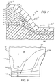
- Blade 10 includes an airfoil 10a and an integral dovetail 10b having a common stacking axis 10c extending between the airfoil and dovetail.
- the airfoil includes a radially inner root 10d, a radially outer tip 10e and axially spaced apart leading edge 10f and trailing edge 10g.
- Blade 10 also includes a first or suction side 10h and an opposite, second, or pressure side 10j.
- Blade 10 may take any suitable configuration, including a pattern that varies three-dimensionally over the entire length of its stacking axis. Thus blade 10 is shown with a thickness A which varies from the dovetail to the tip, and between its leading and trailing edges. Airfoil 10a is typically highly twisted along stacking axis 10c from the root to tip as conventionally required for aerodynamic reasons, and the airfoil curvature at each radial section between the leading and trailing edges also varies as required for aerodynamic performance, with mid-chord sections near the stacking axis being thicker than the leading and trailing edges.
- Fan blade 10 is conventionally configured as a layup of a plurality of composite plies 10k laterally stacked together between the sides of the blade.
- Each of the plies 10k is specifically configured in shape so that collectively the plies 10k form the desired three dimensional profile of the blade 10.
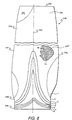
- the fan blade 10 illustrated in Figure 1 is formed from a substantially identical preform 12 illustrated in Figure 2.
- Preform 12 is the initial, uncured state of fan blade 10 which is initially thicker, as represented by its varying thickness B, than the blade thickness A at corresponding portions.
- preform 12 is thicker than blade 10, but otherwise shaped identical to blade 10. Since preform 12 is merely the initial form of the final fan blade 10, it includes corresponding parts such as an airfoil 12a to composite plies 12k, directly corresponding to the same components 10a-k, respectively, for the final fan blade.
- Preform 12 may take any conventional form, and Figure 3 illustrates an exemplary section thereof.
- Each individual composite ply 12k includes a conventional structural fiber 14, such as glass or graphite, in a suitable resin matrix 16.
- Fibers 14 may be in any configuration, such as tape or woven cloth with suitable directional orientation. The tape or cloth may be conventionally pre-impregnated with resin matrix 16.
- Exemplary compositions of composite plies 12k include fiber-thermoset epoxy, fiber-thermoplastic, fiber-bismaleimide, and chopped fiber-epoxy/bismaleimide, or a neat resin such as thermoplastic or thermoset, or an elastomer.
- dovetail 12b has about several hundred composite plies which taper down to a few hundred composite plies at root 12d. The number of plies decreases to about a hundred at tip 12e.
- preform 12 is disposed in a conventional autoclave 18 to undergo consolidation and curing to form a final, cured fan blade 10.
- Autoclave 18 includes a pressure chamber 20, and a bottom mold 22 disposed in chamber 20 and configured to define the second side 12j of preform 12.
- Preform 12 is positioned atop bottom mold 22 with its second side 12j in contact with mold 22.
- a specifically configured caul 24 is positioned atop the preform 12.
- a conventional flexible vacuum sheet 26 is positioned atop caul 24 to provide an effective vacuum seal thereover.
- a conventional vacuum pump 28 is operatively joined to chamber 20 for initially evacuating air from preform 12.
- Conventional means 30 are operatively joined to chamber 20 for heating the chamber and pressurizing the chamber to a suitable pressure P to compress caul 24 and consolidate the preform plies 12k to final shape as the preform undergoes curing.
- Caul 24 provides an effective molding tool which conforms to the shape of preform 12 during the debulking or pre-cure cycle, which requires less heat than the curing cycle and thus takes place at a lower temperature and a shorter time than the curing cycle, so that the preform resin remains cured at this time.
- the caul also conforms to the shape of the preform during the autoclave manufacturing process or curing cycle. Thus, while the thickness of preform 12 is reduced during these cycles, the shape of preform 12 remains unaltered.
- the caul provides stability to the composite plies by distributing the pressure loading throughout the preform during consolidation without causing any shifting or relative movement between adjacent plies. This leads to a decrease in manufacturing defects such as wrinkling and delamination between the ply layers.
- mold 22 forms the second side 12j of the preform, with caul 24 being configured to form the first side 12h of the preform.
- the caul therefore is shaped to conform or correspond to the general shape of both the fan blade and preform 12.
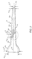
- Figure 5 illustrates an embodiment of caul 24 which includes an airfoil region 24a, a dovetail region 24b, a longitudinal axis 24c, a root 24d, a tip 24e, a leading edge 24i, a trailing edge 24g, a top or outer side 24h, and a bottom or inner side 24j.
- Caul 24 has a structural body 24k which is preferably a composite and includes a plurality of plies.
- the caul is configured to conform to the preform first side 12h, and its bottom side 24j is therefore complementary therewith, and has a bending flexibility which varies over its body for preferentially or selectively varying consolidation of the preform in a suitably corresponding manner to reduce or eliminate defects such as wrinkling, porosity, and delamination of the plies.
- caul body 24k has a thickness C which predeterminedly varies over caul 24 to effect desirable variations in bending flexibility between relatively stiff and pliable portions thereof.
- the elongate preform 12 undergoes a decrease in thickness B from dovetail 12b to airfoil root 12d, and in turn to tip 12e.
- air in the form of voids is trapped within the assembly. Accordingly, during consolidation, compression loading squeezes together the several preform plies 12k to expel the voids, with the curing process also affecting the amount of consolidation achieved.
- caul 24 When caul 24 is positioned in the autoclave, caul root 24d is positioned atop preform root 12d, and caul tip 24e is positioned atop preform tip 12e.
- the caul preferably increases in bending flexibility from its root 24d to its tip 24e to correspond with the decreasing thickness from preform root 12d to preform tip 12e.
- preform dovetail 12b and root 12d In the region of preform dovetail 12b and root 12d, more constraint is required to prevent plastic distortion which leads to undesirable wrinkling.
- suitable constraint is provided in this region of preform 12.
- the thickness varies or tapers slightly, and the amount of consolidation required is also more uniform, as well as less than that required at preform dovetail 12b.
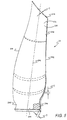
- FIG. 6 A first embodiment of caul 24 is illustrated in Figures 6 and 7.
- body 24k of caul 24 is preferably in the form of a plurality of overlapping composite plies, shown individually numbered 1-8.
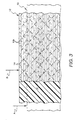
- Figure 7 illustrates an exaggerated cross section of caul 24 with the overlapping composite plies 1-8.
- each of the caul plies 1-8 includes a suitable structural fiber 14 in a suitable resin matrix 16.
- Fiber 14 may take any suitable form, such as a tape or woven sheet of fibers which is preferably pre-impregnated with the resin matrix 16.
- Fiber 14 may be of any suitable composition, such as glass or graphite, and the resin matrix may be of any conventional composition such as those listed above for preform 12 itself.
- Fiber 14 and matrix 16 are visible in Figure 6 through a cut-away portion of top or outer side 24h.
- the individual plies 1-8 which form caul 24 are individually configured so that, upon stackup and curing, they provide the desired variation in bending flexibility along the radial and axial extent of caul 24.
- the caul bottom side 24j is positioned above a suitable mold (not shown) corresponding with the desired profile of the airfoil top or first side 10h ( Figure 1) for use in defining that side in the preform.
- caul 24 uses the eight plies 1-8 stacked atop each other, which corresponds to a total thickness of about 40-50 mils.
- the caul plies 1-8 are disposed generally symmetrically about the longitudinal or radial stacking axis 24c to correspond with the symmetry of the fan blade itself.
- caul airfoil 24a includes only two structural plies 1 and 2, having a total thickness of about 10-15 mils extending downwardly from caul tip 24e along both sides and the leading and trailing edges 24f, 24g, down to about the caul root 24d.
- the number or quantity of plies preferably increases from tip 24e to root 24d which, in the Figure 6 embodiment, is localized near root 24d. From caul root 24d to the bottom of dovetail 24b the number of plies increases sequentially from 2, 3, 4, 5, 6, 7, to 8. After layup of the initial plies 1-8, caul 24 is, conventionally, itself consolidated and cured to complete its manufacture.
- the result is a one-piece unitary solid member having predetermined bending flexibility along its radial and axial extent, controlled in most part by the number of plies, orientation, and configuration in the same manner as any engineered composite structure.
- caul 24 preferably includes a flexible liner 24m integrally joined to the bottom side 24j of the caul body for engaging in abutting contact the preform top side 12h ( Figure 4) in controlling surface finish thereof.
- Liner 24m may be formed of a suitable elastomer having a smooth finish so that the finish of the preform is correspondingly smooth.
- Caul 24 preferably also includes a flexible cover 24n integrally joined to the top side 24h of the caul body for protecting the caul body.
- Cover 24n may be formed of rubber for example, and has a suitable thickness for improving ease of handling of the caul itself while being sufficiently flexible to prevent undesirable restraint of structural plies 1-8.
- the optional liner and cover 24m and 24n improve the use of caul 24, with liner 24m being disposed in direct contact with the preform first side 12h ( Figure 4) in the autoclave, with vacuum sheet 26 thereof disposed atop cover 24n.
- caul plies 1-8 are predeterminedly oriented in body 24k for positioning fibers 14 therein to decrease the bending flexibility, or correspondingly increase the rigidity, near caul root 24d and dovetail 24b for promoting directional consolidation.
- the fibers are oriented perpendicularly to each other in each sheet or ply at 0° and 90° relative to longitudinal axis 24c.
- caul 24 illustrated in Figure 6 includes two generally crescent-shaped cut-outs for effecting only one structural ply above root 24d and along the corresponding leading and trailing edges 24f and 24g for a suitable part-span extent. This affects the desired consolidation in the corresponding regions of the preform.
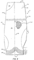
- FIG 8 Illustrated in Figure 8 is a second embodiment of a caul 24B which also includes eight plies 1-8 in a modified form of the configuration illustrated in Figure 6.
- the caul plies 1-8 have the woven fibers 14 in each sheet being disposed perpendicularly to each other, but at ⁇ 45° relative to longitudinal axis 24c.
- the symmetric orientation of overlapping plies 1-8 provides additional plies along axis 24c in a centered peak extending to about the mid-span of airfoil 24a.
- This embodiment provides more uniform consolidation in the preform near its root and dovetail.
- the thickness (and hence bending flexibility) along leading edge 24f if identical to that along trailing edge 249.
- Figure 9 is a graphical representation of isoclines of consolidation for the embodiment of Figure 8, expressed in relative numerical units for preform 12.
- the two arrows indicate the directions from minimum to maximum consolidation in preform root 12d and dovetail 12b.
- the Figure 9 analytical depiction of this consolidation correlates with test results.
- the isoclines indicate more uniform consolidation along preform dovetail 12b which better corresponds to the required final configuration of the resulting fan blade with minimized consolidation distortion.
- Figure 9 illustrates that less consolidation, e.g. minus 10 units, occurs in the airfoil and increases radially downwardly to the bottom of dovetail 12b having a magnitude of minus 50 units, for example.
- Caul 24 is therefore effective for not only providing increased consolidation and contraction at the relatively thicker dovetail 12b, but also for providing a suitable transition in consolidation to the reduced amount required in airfoil 12a without undesirable consolidation distortion.
- the two embodiments illustrated in Figures 6 and 8 have similarity in the required number and configuration of the overlapping plies 1-8 for effecting desired variation in bending flexibility of cauls 24 and 24B, yet also exhibit subtle differences.
- the designs are generally axisymmetrical about longitudinal axis 24c on the top side 24h.
- the bottom side 24j is typically single structural ply 1 extending over the entire surface thereof from leading to trailing edges, and from dovetail to tip, upon which the additional plies 2-8 are suitably stacked in desired locations.
- the maximum number of plies is at dovetail 24b, and decreases in number to root 24d, and further decreases in number part-span before remaining constant at two plies, for example, to the tip.
- Both designs include local cut-outs in second ply 2 to effect a single structural ply 1 for suitable part-span extent at the leading and trailing edges.
- the design of the individual caul depends upon the desired final configuration of the fan blade itself.
- An individual caul design may therefore be made to a specific configuration of the fan blade. This may be accomplished by using conventional analytical tools to predict the complex three dimensional requirements of consolidation in the multi-ply preform, and therefore predicting a suitable configuration for the required caul.
- variable flexibility of the caul may be implemented in any suitable manner such as by using the variation in multiple plies 1-8, illustrated in Figures 6 and 8, with suitable configurations therefor.
- the number of plies may be changed, the orientation of the ply fibers may be changed, and the location of overlapping transition regions may also be changed in order to affect the resultant flexibility of the caul.
- the caul may therefore be tailored either analytically or by systematic variations in the operative parameters to create an optimum caul configuration for a specific part design. In this way, variation in preform consolidation may be optimized for significantly reducing defects such as wrinkles., porosity, and delamination which would otherwise occur without such controlled consolidation.
Landscapes
- Engineering & Computer Science (AREA)
- Mechanical Engineering (AREA)
- Chemical & Material Sciences (AREA)
- Composite Materials (AREA)
- Moulding By Coating Moulds (AREA)
- Structures Of Non-Positive Displacement Pumps (AREA)
- Moulds For Moulding Plastics Or The Like (AREA)
- Casting Or Compression Moulding Of Plastics Or The Like (AREA)
Applications Claiming Priority (2)
| Application Number | Priority Date | Filing Date | Title |
|---|---|---|---|
| US09/415,714 US6290895B1 (en) | 1997-10-14 | 1999-10-12 | Selectively flexible caul and method of use |
| US415714 | 1999-10-12 |
Publications (2)
| Publication Number | Publication Date |
|---|---|
| EP1092529A1 EP1092529A1 (en) | 2001-04-18 |
| EP1092529B1 true EP1092529B1 (en) | 2004-04-07 |
Family
ID=23646877
Family Applications (1)
| Application Number | Title | Priority Date | Filing Date |
|---|---|---|---|
| EP00304877A Expired - Lifetime EP1092529B1 (en) | 1999-10-12 | 2000-06-08 | Selectively flexible caul |
Country Status (4)
| Country | Link |
|---|---|
| US (1) | US6290895B1 (enExample) |
| EP (1) | EP1092529B1 (enExample) |
| JP (1) | JP4666719B2 (enExample) |
| DE (1) | DE60009625T2 (enExample) |
Cited By (1)
| Publication number | Priority date | Publication date | Assignee | Title |
|---|---|---|---|---|
| US11040512B2 (en) | 2017-11-08 | 2021-06-22 | Northrop Grumman Systems Corporation | Composite structures, forming apparatuses and related systems and methods |
Families Citing this family (63)
| Publication number | Priority date | Publication date | Assignee | Title |
|---|---|---|---|---|
| AUPQ171099A0 (en) * | 1999-07-20 | 1999-08-12 | Williames Hi-Tech International Pty Ltd | Improvements to vacuum formed indexable lightweight, recyclable trays |
| US20040040210A1 (en) * | 1999-07-20 | 2004-03-04 | Williames Geoffrey Alan | Vacuum formed indexable lightweight, recyclable trays |
| WO2001041993A2 (en) * | 1999-12-07 | 2001-06-14 | The Boeing Company | Double bag vacuum infusion process and system for low cost, advanced composite fabrication |
| US6533986B1 (en) * | 2000-02-16 | 2003-03-18 | Howmet Research Corporation | Method and apparatus for making ceramic cores and other articles |
| US6431850B1 (en) * | 2000-08-11 | 2002-08-13 | General Electric Company | Composite caul sheet with integral seal used in the fabrication of lightweight airfoils and method of making |
| US6696009B2 (en) * | 2001-03-21 | 2004-02-24 | Sikorsky Aircraft Corporation | Method for controlling thickness during lay-up and fabrication of composite components |
| US6403020B1 (en) * | 2001-08-07 | 2002-06-11 | Howmet Research Corporation | Method for firing ceramic cores |
| US20040032063A1 (en) * | 2002-08-16 | 2004-02-19 | Peter Walther | Process for shaping plate-shaped materials and an arrangement for carrying out the process |
| DE10258935A1 (de) * | 2002-12-13 | 2004-07-15 | Hpp High Performance Products Gmbh | Verfahren zur Herstellung von dreidimensionalen Bauteilen |
| US20040145092A1 (en) * | 2003-01-24 | 2004-07-29 | Mccollum Robert P. | Method of making a composite molded article |
| US7534387B2 (en) * | 2004-02-25 | 2009-05-19 | The Boeing Company | Apparatus and methods for processing composite components using an elastomeric caul |
| CN100406746C (zh) * | 2004-03-23 | 2008-07-30 | 三菱重工业株式会社 | 离心压缩机及叶轮的制造方法 |
| JP4545009B2 (ja) * | 2004-03-23 | 2010-09-15 | 三菱重工業株式会社 | 遠心圧縮機 |
| US7332049B2 (en) * | 2004-12-22 | 2008-02-19 | General Electric Company | Method for fabricating reinforced composite materials |
| US20070205534A1 (en) * | 2006-03-06 | 2007-09-06 | Wen-Tsung Ko | Method for manufacturing a vane of ceiling fan |
| US7850897B2 (en) * | 2007-03-14 | 2010-12-14 | Spectrum Aeronautical, Llc | Method and device for manufacturing a unitary caul sheet |
| GB2456566B (en) * | 2008-01-18 | 2012-03-07 | Gkn Aerospace Services Ltd | A method of manufacturing a polymer matrix composite forming tool |
| CN102037247B (zh) * | 2008-03-28 | 2015-06-24 | 株式会社Ihi | 飞机用燃气涡轮发动机的桨叶及其制造方法 |
| EP2116358B1 (en) * | 2008-05-09 | 2016-06-29 | Saab Ab | Method and apparatus for conforming a blank |
| US8123463B2 (en) * | 2008-07-31 | 2012-02-28 | General Electric Company | Method and system for manufacturing a blade |
| CN102555109B (zh) * | 2010-12-22 | 2014-07-30 | 上海艾郎风电科技发展有限公司 | 用于风力发电叶片生产的合模后固化辅助加热装置 |
| US8613252B2 (en) * | 2011-02-14 | 2013-12-24 | Sikorsky Aircraft Corporation | Co-curing reusable elastomeric caul plate |
| US8591796B2 (en) * | 2011-08-25 | 2013-11-26 | General Electric Company | Methods and apparatus for molding and curing of composites |
| FR2982518B1 (fr) * | 2011-11-15 | 2013-12-20 | Snecma | Conception d'une piece en materiau composite tisse 3d |
| ES2688869T3 (es) * | 2011-12-30 | 2018-11-07 | Vestas Wind Systems A/S | Método y aparato para fabricación de un componente de pala de turbina eólica con temperatura de curado uniforme |
| EP2653297A1 (de) * | 2012-04-20 | 2013-10-23 | Nordex Energy GmbH | Verfahren zur Herstellung eines Windenergieanlagenbauteils |
| JP5982999B2 (ja) * | 2012-05-01 | 2016-08-31 | 株式会社Ihi | 動翼及びファン |
| EP3026216B1 (en) * | 2014-11-20 | 2017-07-12 | Rolls-Royce North American Technologies, Inc. | Composite blades for gas turbine engines |
| US9828862B2 (en) | 2015-01-14 | 2017-11-28 | General Electric Company | Frangible airfoil |
| WO2016115352A1 (en) * | 2015-01-14 | 2016-07-21 | General Electric Company | A frangible composite airfoil |
| US9878501B2 (en) * | 2015-01-14 | 2018-01-30 | General Electric Company | Method of manufacturing a frangible blade |
| US10449737B2 (en) | 2015-03-04 | 2019-10-22 | Ebert Composites Corporation | 3D thermoplastic composite pultrusion system and method |
| US10124546B2 (en) | 2015-03-04 | 2018-11-13 | Ebert Composites Corporation | 3D thermoplastic composite pultrusion system and method |
| US9616623B2 (en) | 2015-03-04 | 2017-04-11 | Ebert Composites Corporation | 3D thermoplastic composite pultrusion system and method |
| US9963978B2 (en) | 2015-06-09 | 2018-05-08 | Ebert Composites Corporation | 3D thermoplastic composite pultrusion system and method |
| GB201514579D0 (en) | 2015-08-17 | 2015-09-30 | Invibio Device Component Mfg Ltd | A device |
| JP6703842B2 (ja) * | 2016-01-20 | 2020-06-03 | 株式会社Ihi | 繊維強化複合部材の成形装置及び繊維強化複合部材の成形方法 |
| EP3436252A1 (en) * | 2016-03-28 | 2019-02-06 | General Electric Company | Rotor blade tip mold assembly including solid core and method for forming rotor blade tip |
| US10677259B2 (en) | 2016-05-06 | 2020-06-09 | General Electric Company | Apparatus and system for composite fan blade with fused metal lead edge |
| US10391684B1 (en) | 2016-11-30 | 2019-08-27 | Spintech, LLC | Cauls and methods of using cauls to produce composite articles |
| US10760600B2 (en) | 2017-10-27 | 2020-09-01 | General Electric Company | Method of applying riblets to an aerodynamic surface |
| CN108724296B (zh) * | 2018-05-22 | 2020-07-28 | 徐州腾睿智能装备有限公司 | 一种用于农村生活垃圾处理设备中的增速风扇装置 |
| JP6484378B1 (ja) * | 2018-09-21 | 2019-03-13 | 太平洋工業株式会社 | 樹脂成形品及び樹脂成形品の製造方法 |
| US11155047B2 (en) | 2018-10-08 | 2021-10-26 | Textron Innovations Inc. | Caul body and a method for forming a composite structure |
| US10760428B2 (en) | 2018-10-16 | 2020-09-01 | General Electric Company | Frangible gas turbine engine airfoil |
| US11434781B2 (en) | 2018-10-16 | 2022-09-06 | General Electric Company | Frangible gas turbine engine airfoil including an internal cavity |
| US10837286B2 (en) | 2018-10-16 | 2020-11-17 | General Electric Company | Frangible gas turbine engine airfoil with chord reduction |
| US11111815B2 (en) | 2018-10-16 | 2021-09-07 | General Electric Company | Frangible gas turbine engine airfoil with fusion cavities |
| US10746045B2 (en) | 2018-10-16 | 2020-08-18 | General Electric Company | Frangible gas turbine engine airfoil including a retaining member |
| US11149558B2 (en) | 2018-10-16 | 2021-10-19 | General Electric Company | Frangible gas turbine engine airfoil with layup change |
| US20200318486A1 (en) | 2019-04-04 | 2020-10-08 | General Electric Company | Monolithic Composite Blade and Platform |
| CN110826222B (zh) * | 2019-11-05 | 2023-03-24 | 上海波客实业有限公司 | 一种汽车碳纤维增强复合材料覆盖件正向开发方法 |
| US11865798B2 (en) * | 2020-02-13 | 2024-01-09 | The Boeing Company | Caul plates for preforms that undergo pick and placement |
| FR3109821B1 (fr) * | 2020-05-04 | 2022-12-23 | Safran Aircraft Engines | Vérification du positionnement d’une préforme fibreuse dans une aube |
| US11352891B2 (en) | 2020-10-19 | 2022-06-07 | Pratt & Whitney Canada Corp. | Method for manufacturing a composite guide vane having a metallic leading edge |
| CN114905770B (zh) * | 2021-02-08 | 2024-03-22 | 中国航发商用航空发动机有限责任公司 | 叶片成型方法和模具 |
| US11725524B2 (en) | 2021-03-26 | 2023-08-15 | General Electric Company | Engine airfoil metal edge |
| US12116903B2 (en) | 2021-06-30 | 2024-10-15 | General Electric Company | Composite airfoils with frangible tips |
| US11674399B2 (en) | 2021-07-07 | 2023-06-13 | General Electric Company | Airfoil arrangement for a gas turbine engine utilizing a shape memory alloy |
| US11668317B2 (en) | 2021-07-09 | 2023-06-06 | General Electric Company | Airfoil arrangement for a gas turbine engine utilizing a shape memory alloy |
| US11767607B1 (en) | 2022-07-13 | 2023-09-26 | General Electric Company | Method of depositing a metal layer on a component |
| GB202319599D0 (en) * | 2023-12-20 | 2024-01-31 | Rolls Royce Plc | Variable stiffness tool |
| US12448897B2 (en) * | 2024-01-31 | 2025-10-21 | Rtx Corporation | Gas turbine engine component formed by CMCS and having a compressed insert with tapered ends |
Family Cites Families (11)
| Publication number | Priority date | Publication date | Assignee | Title |
|---|---|---|---|---|
| JPS5016298A (enExample) * | 1973-05-30 | 1975-02-20 | ||
| US4608220A (en) | 1984-12-20 | 1986-08-26 | The Boeing Company | Method of forming composite material articles |
| US5071338A (en) | 1987-09-08 | 1991-12-10 | United Technologies Corporation | Tool for forming complex composite articles |
| CN1042692A (zh) * | 1988-11-14 | 1990-06-06 | 通用电气公司 | 反转的飞机螺旋桨叶 |
| JP2685553B2 (ja) * | 1988-12-16 | 1997-12-03 | 富士重工業株式会社 | 複合材の成形方法 |
| JP2695214B2 (ja) * | 1988-12-20 | 1997-12-24 | 富士重工業株式会社 | 複合材構造体の成形方法 |
| US5038291A (en) | 1989-04-03 | 1991-08-06 | General Electric Company | Computerized ply pattern generation |
| JP3004309B2 (ja) * | 1990-04-09 | 2000-01-31 | 富士重工業株式会社 | 繊維強化樹脂積層体の製造方法 |
| US5152949A (en) | 1990-12-19 | 1992-10-06 | United Technologies Corporation | Tooling method for resin transfer molding |
| FR2685249B1 (fr) * | 1991-12-24 | 1994-02-11 | Snecma | Procede de fabrication d'une pale de soufflante en materiau composite et outillage de moulage. |
| US5520532A (en) * | 1994-08-01 | 1996-05-28 | United Technologies Corporation | Molding assembly for forming airfoil structures |
-
1999
- 1999-10-12 US US09/415,714 patent/US6290895B1/en not_active Expired - Lifetime
-
2000
- 2000-06-08 EP EP00304877A patent/EP1092529B1/en not_active Expired - Lifetime
- 2000-06-08 DE DE60009625T patent/DE60009625T2/de not_active Expired - Lifetime
- 2000-06-09 JP JP2000172838A patent/JP4666719B2/ja not_active Expired - Fee Related
Cited By (1)
| Publication number | Priority date | Publication date | Assignee | Title |
|---|---|---|---|---|
| US11040512B2 (en) | 2017-11-08 | 2021-06-22 | Northrop Grumman Systems Corporation | Composite structures, forming apparatuses and related systems and methods |
Also Published As
| Publication number | Publication date |
|---|---|
| US6290895B1 (en) | 2001-09-18 |
| DE60009625T2 (de) | 2005-06-23 |
| EP1092529A1 (en) | 2001-04-18 |
| DE60009625D1 (de) | 2004-05-13 |
| JP2001129844A (ja) | 2001-05-15 |
| JP4666719B2 (ja) | 2011-04-06 |
Similar Documents
| Publication | Publication Date | Title |
|---|---|---|
| EP1092529B1 (en) | Selectively flexible caul | |
| US11208904B2 (en) | Method for manufacturing a vane from a composite material with a fitted metal leading edge for a gas turbine | |
| JP3839476B2 (ja) | 翼構造体の製造方法及び製造装置 | |
| KR100311562B1 (ko) | 헬리콥터로터블레이드용섬유보강복합익형및그의제조방법 | |
| EP2441571B1 (en) | Proces for manufacturing a composite component | |
| CN102325646B (zh) | 通过嵌入预固化纤维增强树脂层制造风轮机叶片的方法 | |
| EP2789534B1 (en) | Multi-box wing spar and skin | |
| US10914176B2 (en) | Composite blade and method of manufacturing composite blade | |
| CN114746256B (zh) | 用于飞行器发动机的复合材料叶片以及用于制造和修复该复合材料叶片的方法 | |
| CN113423550B (zh) | 与风力涡轮机叶片制造相关的改进 | |
| EP2357075B1 (en) | Method for manufacturing a complex-geometry panel with pre-impregnated composite material | |
| US8353696B2 (en) | Semi-rigid tool having sections that vary from one another in rigidity | |
| DK2666615T3 (en) | Process for producing a rotor blade half shell for a wind power plant or for producing a rotor blade for a wind power plant, and production form for this purpose | |
| JP2017528641A (ja) | ガスタービンエンジン用の複合材料製案内翼及びその製造方法 | |
| US5091029A (en) | Method of manufacturing a unitary, multi-legged helicopter rotor flexbeam made solely of composite materials | |
| CN115485455B (zh) | 复合材料涡轮机轮叶及其制造方法 | |
| CN101351327B (zh) | 具有嵌入的预固化模具的复合结构的制造工艺 | |
| US20240239062A1 (en) | Vane made of composite material comprising a metallic reinforcement and method for manufacturing such a vane | |
| EP3248763B1 (en) | Method of constructing composite structures without tooling dams | |
| US10125617B2 (en) | Composite structure and a method of fabricating the same | |
| WO2020083472A1 (en) | A method of manufacturing a propeller blade assembly | |
| US20210069997A1 (en) | Method for manufacturing a composite material structure using a cocuring process | |
| CN119910928B (zh) | 一种复合材料机匣法兰边成型方法 | |
| US20230311428A1 (en) | Method for manufacturing a composite part for a turbomachine |
Legal Events
| Date | Code | Title | Description |
|---|---|---|---|
| PUAI | Public reference made under article 153(3) epc to a published international application that has entered the european phase |
Free format text: ORIGINAL CODE: 0009012 |
|
| AK | Designated contracting states |
Kind code of ref document: A1 Designated state(s): DE FR GB |
|
| AX | Request for extension of the european patent |
Free format text: AL;LT;LV;MK;RO;SI |
|
| 17P | Request for examination filed |
Effective date: 20011018 |
|
| AKX | Designation fees paid |
Free format text: DE FR GB |
|
| 17Q | First examination report despatched |
Effective date: 20021112 |
|
| GRAP | Despatch of communication of intention to grant a patent |
Free format text: ORIGINAL CODE: EPIDOSNIGR1 |
|
| GRAS | Grant fee paid |
Free format text: ORIGINAL CODE: EPIDOSNIGR3 |
|
| GRAA | (expected) grant |
Free format text: ORIGINAL CODE: 0009210 |
|
| AK | Designated contracting states |
Kind code of ref document: B1 Designated state(s): DE FR GB |
|
| REG | Reference to a national code |
Ref country code: GB Ref legal event code: FG4D |
|
| REF | Corresponds to: |
Ref document number: 60009625 Country of ref document: DE Date of ref document: 20040513 Kind code of ref document: P |
|
| ET | Fr: translation filed | ||
| PLBE | No opposition filed within time limit |
Free format text: ORIGINAL CODE: 0009261 |
|
| STAA | Information on the status of an ep patent application or granted ep patent |
Free format text: STATUS: NO OPPOSITION FILED WITHIN TIME LIMIT |
|
| 26N | No opposition filed |
Effective date: 20050110 |
|
| REG | Reference to a national code |
Ref country code: FR Ref legal event code: PLFP Year of fee payment: 17 |
|
| PGFP | Annual fee paid to national office [announced via postgrant information from national office to epo] |
Ref country code: GB Payment date: 20160627 Year of fee payment: 17 |
|
| PGFP | Annual fee paid to national office [announced via postgrant information from national office to epo] |
Ref country code: FR Payment date: 20160628 Year of fee payment: 17 |
|
| PGFP | Annual fee paid to national office [announced via postgrant information from national office to epo] |
Ref country code: DE Payment date: 20160628 Year of fee payment: 17 |
|
| REG | Reference to a national code |
Ref country code: DE Ref legal event code: R119 Ref document number: 60009625 Country of ref document: DE |
|
| GBPC | Gb: european patent ceased through non-payment of renewal fee |
Effective date: 20170608 |
|
| REG | Reference to a national code |
Ref country code: FR Ref legal event code: ST Effective date: 20180228 |
|
| PG25 | Lapsed in a contracting state [announced via postgrant information from national office to epo] |
Ref country code: GB Free format text: LAPSE BECAUSE OF NON-PAYMENT OF DUE FEES Effective date: 20170608 Ref country code: DE Free format text: LAPSE BECAUSE OF FAILURE TO SUBMIT A TRANSLATION OF THE DESCRIPTION OR TO PAY THE FEE WITHIN THE PRESCRIBED TIME-LIMIT Effective date: 20180103 |
|
| PG25 | Lapsed in a contracting state [announced via postgrant information from national office to epo] |
Ref country code: FR Free format text: LAPSE BECAUSE OF NON-PAYMENT OF DUE FEES Effective date: 20170630 |