EP1091696B1 - Dispositif pour inserer une prothese du genou - Google Patents
Dispositif pour inserer une prothese du genou Download PDFInfo
- Publication number
- EP1091696B1 EP1091696B1 EP98928043A EP98928043A EP1091696B1 EP 1091696 B1 EP1091696 B1 EP 1091696B1 EP 98928043 A EP98928043 A EP 98928043A EP 98928043 A EP98928043 A EP 98928043A EP 1091696 B1 EP1091696 B1 EP 1091696B1
- Authority
- EP
- European Patent Office
- Prior art keywords
- femur
- axis
- pivot
- base part
- adjustment device
- Prior art date
- Legal status (The legal status is an assumption and is not a legal conclusion. Google has not performed a legal analysis and makes no representation as to the accuracy of the status listed.)
- Expired - Lifetime
Links
- 210000003127 knee Anatomy 0.000 title description 9
- 210000000689 upper leg Anatomy 0.000 claims abstract description 122
- 238000002271 resection Methods 0.000 claims abstract description 28
- 210000000629 knee joint Anatomy 0.000 claims abstract description 16
- 238000002513 implantation Methods 0.000 claims abstract description 6
- 238000005520 cutting process Methods 0.000 claims description 34
- 210000002414 leg Anatomy 0.000 claims description 20
- 210000000988 bone and bone Anatomy 0.000 claims description 12
- 238000004873 anchoring Methods 0.000 claims description 5
- 238000005259 measurement Methods 0.000 claims 1
- 210000002303 tibia Anatomy 0.000 description 72
- 239000000523 sample Substances 0.000 description 16
- 238000006073 displacement reaction Methods 0.000 description 12
- 239000007943 implant Substances 0.000 description 12
- 238000000034 method Methods 0.000 description 7
- 210000003041 ligament Anatomy 0.000 description 5
- 239000002184 metal Substances 0.000 description 3
- 229910052751 metal Inorganic materials 0.000 description 3
- 229910000639 Spring steel Inorganic materials 0.000 description 2
- 238000005452 bending Methods 0.000 description 2
- 238000005553 drilling Methods 0.000 description 2
- 230000036512 infertility Effects 0.000 description 2
- 238000003780 insertion Methods 0.000 description 2
- 230000037431 insertion Effects 0.000 description 2
- 210000001699 lower leg Anatomy 0.000 description 2
- 210000003205 muscle Anatomy 0.000 description 2
- 238000001356 surgical procedure Methods 0.000 description 2
- 241000309551 Arthraxon hispidus Species 0.000 description 1
- 208000005189 Embolism Diseases 0.000 description 1
- 229910000831 Steel Inorganic materials 0.000 description 1
- 241001422033 Thestylus Species 0.000 description 1
- 208000007536 Thrombosis Diseases 0.000 description 1
- 241001227561 Valgus Species 0.000 description 1
- 241000469816 Varus Species 0.000 description 1
- 238000011882 arthroplasty Methods 0.000 description 1
- 230000002457 bidirectional effect Effects 0.000 description 1
- 210000004439 collateral ligament Anatomy 0.000 description 1
- 239000002131 composite material Substances 0.000 description 1
- 239000012141 concentrate Substances 0.000 description 1
- 230000000694 effects Effects 0.000 description 1
- 238000011067 equilibration Methods 0.000 description 1
- 210000002683 foot Anatomy 0.000 description 1
- 230000005484 gravity Effects 0.000 description 1
- 230000000977 initiatory effect Effects 0.000 description 1
- 238000007689 inspection Methods 0.000 description 1
- 231100000518 lethal Toxicity 0.000 description 1
- 230000001665 lethal effect Effects 0.000 description 1
- 238000003754 machining Methods 0.000 description 1
- 150000002739 metals Chemical class 0.000 description 1
- 238000002559 palpation Methods 0.000 description 1
- 210000004417 patella Anatomy 0.000 description 1
- 230000001575 pathological effect Effects 0.000 description 1
- 230000035515 penetration Effects 0.000 description 1
- 238000003825 pressing Methods 0.000 description 1
- 230000000284 resting effect Effects 0.000 description 1
- 238000000926 separation method Methods 0.000 description 1
- 210000004872 soft tissue Anatomy 0.000 description 1
- 239000007787 solid Substances 0.000 description 1
- 238000003892 spreading Methods 0.000 description 1
- 239000010959 steel Substances 0.000 description 1
- 238000004804 winding Methods 0.000 description 1
Images


Classifications
-
- A—HUMAN NECESSITIES
- A61—MEDICAL OR VETERINARY SCIENCE; HYGIENE
- A61B—DIAGNOSIS; SURGERY; IDENTIFICATION
- A61B17/00—Surgical instruments, devices or methods, e.g. tourniquets
- A61B17/14—Surgical saws ; Accessories therefor
- A61B17/15—Guides therefor
- A61B17/154—Guides therefor for preparing bone for knee prosthesis
- A61B17/155—Cutting femur
-
- A—HUMAN NECESSITIES
- A61—MEDICAL OR VETERINARY SCIENCE; HYGIENE
- A61B—DIAGNOSIS; SURGERY; IDENTIFICATION
- A61B90/00—Instruments, implements or accessories specially adapted for surgery or diagnosis and not covered by any of the groups A61B1/00 - A61B50/00, e.g. for luxation treatment or for protecting wound edges
- A61B90/39—Markers, e.g. radio-opaque or breast lesions markers
- A61B2090/3904—Markers, e.g. radio-opaque or breast lesions markers specially adapted for marking specified tissue
- A61B2090/3916—Bone tissue
-
- A—HUMAN NECESSITIES
- A61—MEDICAL OR VETERINARY SCIENCE; HYGIENE
- A61B—DIAGNOSIS; SURGERY; IDENTIFICATION
- A61B90/00—Instruments, implements or accessories specially adapted for surgery or diagnosis and not covered by any of the groups A61B1/00 - A61B50/00, e.g. for luxation treatment or for protecting wound edges
- A61B90/39—Markers, e.g. radio-opaque or breast lesions markers
- A61B2090/3983—Reference marker arrangements for use with image guided surgery
Definitions
- the present invention relates to a device which allows a surgeon to Implantation of a total knee joint endoprosthesis Resection of the femur and tibia in an extremely precise manner Way to perform.
- a total knee joint endoprosthesis consists of an am Femur and a component attached to the tibia. Before the total joint arthroplasty can be implanted the adjacent bone areas of the femur and the Tibia to be resected appropriately Norman contact surfaces according to the geometry of the To create endoprostheses. Usually the Frontals of the tibia and femur resected. At least the femur also receives at least one so-called dorsal and a ventral incision, because the Femoral part of total endoprostheses usually U-shaped is designed. The generally from manufacturers of Instruments offered to knee prostheses do not allow the required bone cuts on the femur and on the tibia with the required accuracy.
- Such an instrument is from EP 0 322 363 A1 known.
- This set of instruments uses a Extra medullary means for aligning the tibia and femur (extramedullary alignment system) and has the disadvantage that the alignment of the femur only with the help of a X-ray apparatus can be determined.
- the Attachment of the reference system for the bone cuts after A sense of proportion, with the reference system also providing access to Operating field difficult.
- Another set of instruments is from EP 0 691 110 A2 known.
- This set of instruments uses a intramedullary means to align the tibia and femur (intramedullary alignment system) and has the disadvantage on that for mutual fixation of the tibia and femur A guide spike is required, which is in the Tibial or femoral marrow space is introduced. This intervention in the medullary can cause thrombosis or embolism, what can be lethal.
- the object of the present invention is a device to determine resection cuts on the femur and on the tibia to prepare a Implantation of a total knee joint endoprosthesis create which is easily and reliably reproducible is to be carried out.
- the device according to the invention comprises in one advantageous embodiment, a reference device consisting essentially of a detachable in the distal Area of the femur lockable base part and a articulated and / or slidable with the base part connected reference body, which is a coordinate system X, Y, Z has determining means, the orientation of the reference body with respect to the femur is positionable and with a between the Acting reference body and the base part Actuating means for fixing their mutual position is provided, and wherein the coordinate system X, Y, Z determining means for the aligned fastening of Machining aids such as a cutting jig, one Base bar or a measuring device are configured.
- a reference device consisting essentially of a detachable in the distal Area of the femur lockable base part and a articulated and / or slidable with the base part connected reference body, which is a coordinate system X, Y, Z has determining means, the orientation of the reference body with respect
- the reference device comes with a variety of differently designed means on the femur attachable, for example with bone screws, or the femur at least partially comprehensive gripping arms, which can also have spines for better anchoring, which penetrate the femur.
- the device according to the invention comprises in one Another advantageous embodiment is an extra medullary and releasably attachable in the distal area of the femur Reference device, its orientation with respect to the femur is positionable exactly, as well as an extramedullary and Tibial splint can be detachably attached to the tibia, the Alignment of the tibia splint with respect to the tibia is positionable, and a the reference device as well as releasably firmly connecting the tibia splint Fastening device.
- This embodiment according to the invention has the advantage on that the tibia with respect to the femur in an exact defined position and can then be fixed. Therefore, the direction of the resection cuts can the tibia via the cutting device attached to the femur be specified.
- the position of the tibia can be related the femur can be adjusted precisely, e.g. Correct the course of the mechanical leg axis.
- Fastening device U-shaped or rectangular designed so that the surgical area on the knee too largely free when the fastening device is attached is accessible.
- the device according to the invention comprises in one another advantageous embodiment, a detachable on Lockable distal area of the femur Reference device, its orientation with respect to the femur is positionable exactly, as well as one with the Reference device movably connected Cutting device, in particular a cutting gauge for Carrying a saw blade or a sawing device a saw blade, the orientation of the Cutting device, in particular of the saw blade at least determined by the orientation of the reference device is.
- Cutting devices can be used with use different cutting methods to Example saws, ultrasonic separators or the use of lasers.
- the inventive Device allows the cutting device in this way make the cut in the intended direction runs. To create the cut turns out to be one advantageous method of using a saw.
- the Sawing device a saw blade, the course of which a Saw blade level defined, the sawing device with a connecting means on the reference device or the adjusting device is attached, and wherein the Connection means and the sawing device in such a way is designed so that the saw blade is exclusively in the saw blade level is slidably mounted.
- This embodiment has the advantage that the Alignment of the saw blade is fixed so that the surgeon only focuses on moving the Saw blade towards the bone and on the implementation of the Resection can concentrate, knowing that the Alignment of the resection plane is correct. This means for the surgeon a significant relief during the Resection, he can essentially focus on that Focus on cutting, focusing on possibly can focus on existing obstacles such as tapes without care about the direction of the saw have to.
- the device according to the invention is motorized driven.
- a computer can also be provided which is the process of the device as well as the cutting monitored or even controlled.
- Resection incisions on the femur or tibia are particularly important performed by using a reference device on the distal Area of the femur fixed and then with respect to the Direction of the femur is aligned, and by a cutting jig for guiding a saw blade or a Sawing device with a saw blade with the aligned Reference device slidably connected and in one determine the direction of the resection cut Alignment is done, and by aligning with that guided saw blade the resection is performed.
- An essential idea of the inventive Device for The insertion of a total knee joint endoprosthesis is the Use of a reference system, which on the femur 1 can be anchored.
- This reference system serves as a reference for all manipulations and procedural steps to the tibia 2 with respect to the femur 1 and the resection the articular surfaces.
- the one anchored to the femur 1 The reference system is in an advantageous embodiment in its orientation with respect to the femur 1 adjustable the reference system in particular in the direction of loading Align the femur 1 in a straight line.
- Fig. 1a shows a base plate 3, which holes 3b, 3c, 3d has for receiving bone screws 4.
- Die Base plate 3 as shown in the bottom view according to FIG. 1b, three spaced apart Contact surfaces 3a, which lie on the femur 1 come so that the three-point support thus formed Tilt-free resting on the femur 1 guaranteed.
- the base plate 3 also has an opening 3f for receiving a bayonet lock and two alignment holes 3e, 3g.
- the bore 3b, as in Fig. 1a illustrated a countersink.
- the base plate 3 is, as shown in Fig. 3, in the Proximity of the condyles 1a in this way on the femur 1 arranged that the formed by the holes 3g, 3e Axis preferably in the direction of the loading axis 19b of the Femur 1 runs.
- a drilling jig two Steinmann nails roughly in the direction of the Load axis 19b set in the femur 1 and then the Base plate 3 placed on the femur 1 so that each a Steinmann nail runs through the holes 3g, 3e.
- a drilling jig is placed on the holes 3b, 3c, 3d the base plate 3, then holes in the femur 1 drilled and then inserted bone screws 4, so that the base plate 3, in its longitudinal orientation extending approximately in the direction of the load axis 19b, through the bone screws 4 with the femur 1 connected is.
- the device according to the invention has in one preferred embodiment, a reference device 5 which can be firmly connected to the base plate 3, the mutual position of base plate 3 and Reference device 5 is adjustable to the course of the Resection lines on the femur and tibia as exact as possible adjust.
- Figures 2a to 2c show such a Reference device 5, which has sub-elements, whose alignment defines a coordinate system X, Y, Z, with which coordinate system all others Manipulations and cuts on the femur 1 and tibia 2 be made.
- the reference device 5 comprises a base part 5a which is a locking part 5c of a bayonet lock is arranged with axis of rotation 5b and actuating lever 5d.
- the base part 5a is thus made with the base plate 3 connected that the lever 5d in the position shown is brought, then the closure member 5c in the Opening 3f is inserted, and then the snap-in part 5g is inserted into the countersink of the hole 3b ..
- the operating lever 5d in the direction 5e moved so that the formed by the parts 5c, 3f Bayonet lock snaps into place and the base part 5a firmly but is detachably connected to the base plate 3.
- a reference body 5o has longitudinal bores 5q with screws 5r fixed to the swivel plate 5h connectable.
- the longitudinal hole 5q also as an elongated hole is wider than the shaft of the screw 5r designed.
- the Reference body 5o due to the linear expansion of the Longitudinal bores 5q in the direction of movement 5s either can be moved in parallel or also around the axis of rotation 5t slidable in the direction of movement 5u. So the Reference body 5o with respect to the pivot plate 5h slidable, and especially slightly offset, and firmly connect with the screws 5r.
- Reference body 5o defined via the reference surfaces 5p as well as those firmly connected to the reference body 5o Forks 5m the alignment of the coordinate system X, Y, Z, which forms the reference coordinate system. in the As can be seen from FIG. 2c, reference body 5o is a Guide opening 5z arranged which one in the X direction longitudinal guide for a rack 10a formed.
- the reference body 5o has one in its Internally arranged worm gear 5w, which two includes vertical axes of rotation 5y, wherein at the an axis of rotation 5y a thumbscrew 5v as well as within of the reference body 50, a worm is arranged, and on the other axis of rotation 5y a gear 5w and an in the longitudinal guide 5z protruding gear 5x, which for Engagement in the rack 10a is determined.
- the gear 5x could also be directly on a 5y axis Knurled screw 5v to be attached, so that a Worm gear 5w could be dispensed with.
- 3 shows a femur 1, on which the base plate 3 is screwed on.
- the reference device 5 is with the Base plate 3 connected and can by pressing the Operating lever 5d released and removed at any time be reattached. 3 is also in the X direction longitudinal guide 5z visible.
- the Reference device 5 can also be configured such that this in addition to the pivot axis 5i in a Swivel axis 5i perpendicular second Pivot axis 5j with respect to the base part 5a in Direction of movement 5f is pivotally mounted, the Swivel angle can be fixed by screws and is fixable.
- the reference device 5 could also without the pivot axis 5i, only one Have pivot axis 5j.
- Fig. 4 symbolically shows the reference body 5o, in the Longitudinal guide 5z an insertion and holding part 6a one Control gauge 6 is inserted.
- the control gauge 6 comprises a holder 6b with a transparent attached to it Body 6d with grid lines 6e.
- the control gauge 6 serves for aligning the swivel plate 5h in the swivel direction 5k.
- the plug-in part is in the arrangement according to FIG. 3 6a inserted in the longitudinal guide 5z and then the in Direction of the holding part 6a or in the X direction slidably mounted transparent body 6d moved with holder 6b so that the transparent Body 6d, as indicated in Fig. 4, immediately in front of the Femoral condyle 1a comes to rest.
- the Grid lines 6e run with respect to that through the Reference body 5o predetermined coordinate system in Y and Z-direction.
- the transparent body 6d By turning the screws 51 accordingly can the transparent body 6d about the pivot axis 5i can be rotated.
- the location of the transparent body 6d by moving the Reference body 5o in the direction 5s or in the direction 5u can be set.
- the location of the Reference body 5o or the coordinate system in the Y and Z directions with respect to the position of the condyles 1a can be set very precisely.
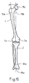
- the anatomical axis 19a of the femur 1 is 19b relative to this loading axis inclined.
- the course of tibia 2 defines one mechanical axis 19d. Point in the position shown the femur 1 and the tibia 2 have a flexion of 0 ° on and the load axis 19b and the mechanical axis 19d are congruent.
- Fig. 5 shows an alignment rod 7, which the Reference body 5o with respect to the position of the femoral head 19c allowed to align.
- the alignment rod 7 includes one Mounting block 7a, which is by means of a knurled screw 7b can be attached to the fork 5m.
- a telescopic rod 7e with end pointer 7f is over the joint 7d with axis of rotation 7g and the bracket 7c with axis of rotation 7h on the mounting block 7a stored.
- the alignment rod 7 is designed and arranged on the reference device 5 that the Telescopic rod 7e essentially or as precisely as possible in the X direction runs, and pivotally mounted in the XY plane is.
- the position of the reference body 5o is also solved Screws 5r adjusted so that by palpation, for example with the so-called "two-finger method", the center of the femoral head 19c is felt, and then the end pointer 7f of the telescopic rod 7e on the thigh 1c is placed at this point, creating the reference body 5o is aligned such that the projection of the X axis (in the sagittal direction) through the center of the Hip head 19c runs. It can also help the course of the X axis of the grid lines 6e be set so that the X axis passes through the center of the Condyle 1a runs. Thus the X axis runs from one 15, congruent to Load axis 19b.
- the screws 5r are tightened and thereby the position of the reference body 5o with respect to the Swivel plate fixed 5h.
- the reference system or orthogonal axes defined in the X, Y and Z directions established.
- the reference device 5 has the Advantage on that all settings made on the Reference device 5 were made and thus quasi are stored on this. Therefore, it is possible reference device 5 set in this way via the To release bayonet lock 5b from the base plate 3 and to remove at the femur 1 or tibia 2 more To carry out manipulations. At a later time can the reference device 5 back on the base plate 3 are attached, the axes in the X, Y and Z directions run as previously defined and therefore no longer need to be set.
- the reference device 5 can be seen in that the course of the axes X, Y and Z with respect to the Position of the femur 1 and the condyles 1a very precisely let set.
- the reference device 5 could also be so simple that an adjustment of the reference body 5o with respect to the base plate 3 only in one or two dimensions is possible.
- base plate 3 and Reference device 5 can be in a another, simpler embodiment on the base plate 3 are omitted, in which the base part 5a Reference device 5 is screwed directly onto the femur 1.
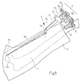
- a tibia splint 8 is used to align the tibia 2 provided, which is shown in Figures 6 and 7.
- the tibia splint 8 is preferably on the tibia 2 in this way attached that the tibial splint 8, in a sagittal 15, congruent to the mechanical Axis 19d of the tibia 2 runs.
- a tibia plate 8a having two bores 8b with two Bone screws 8c anchored to the tibia 2.
- On Support part 8d is via a lockable ball joint 8x and the connecting part 8y with the tibia plate 8a connected.
- the ball joint 8x is within the 8x designated body arranged.
- a tibia rod 8k opens via a stop part 8i and a stop 8e into one End section 8h.
- the tibia rod 8k is in the released state displaceable in the direction of displacement 8f, with the Support web 8d a screw 8g is connected, which in tightened the tibia rod 8k firmly with the body 8x fixed, whereby the position of the tibia rod 8k in Movement direction 8f is fixed.
- On the knee joint far end is a support part 8s with support 8t on Lower leg 2a created and with this, for example fixed with the help of bandages.
- a sliding part 8u is with respect to the support part 8s in the direction of displacement 8w slidable and fixable with a screw 8v.
- the Tibial rod 8k opens into a sliding rod 81, which with respect to the longitudinal direction 8n of the tibia rod 8k slidably supported and with the help of a knurled screw 8m can be fixed with the tibia rod 8k.
- On the sliding part 8u is a rod-shaped holder 8o-projecting, which in a guide part 8p of the displacement rod 81 insertable, adjustable in the 8r direction, and with a knurled screw 8q can be fixed.
- the described Adjustment possibilities of the tibia rod 8k with respect to the Tibial plate 8a and the support part 8s allow this Adjust the course so that the tibia rod 8k in sagittal direction congruent with the anatomical axis 19d of the tibia 2 runs.
- Clamping instrument 20 of which an embodiment in FR 2 648 699, between the femur 1 and the tibia 2 introduced.
- the tensioning instrument 20 is based on the principle of a Spreading pliers and serves the articular surfaces of the tibia 2 and the femur 1 individually on the medial or lateral condyle apart so that the desired orientation arises between femur 1 and tibia 2.
- the tibia rod 8k the course of the mechanical axis 19d the tibia 2 can now indicate the tibia 2 by a corresponding adjustment of the tensioning device 20 in this way that the 8k tibial rod is sagittal is congruent with the alignment rod 7.
- the Leg axis also slightly angled in the varus-valgus direction be set to gradual. So there is Intends an angle between the possibility Introduce loading axis 19b and the tibia axis 19d.
- the Fastening bracket 9 comprises a tibia splint holder 9a the end portion 8h of the knurled screw 9b Tibial rod 8k can be firmly clamped.
- the mounting bracket 9 further includes a bracket base part 9g and a Bracket adjustment part 9c, which with respect to the bracket base 9g adjustable in the longitudinal direction 9f and with a Knurled screw 9h is fixable.
- the tibia splint holder 9a can be pushed in the sliding direction 9e with the Bracket adjustment part 9c connected and with the knurled screw 9d fixable.
- the temple base part 9g is fixed with a Crossbar part 9i connected, which a recess 9k for Has support on the reference body 5o.
- the Bracket cross part 9i is fixed with a knurled screw 91 the reference body 5o connectable.
- the majority Adjustment options of the mounting bracket 9 allow it the end section 8h of the tibia rod 8k in the predetermined Position to be firmly connected to the reference body 5o.
- the femur 1 and the tibia 2 are in one precisely defined location mutually fixed.
- the loading axis 19b is preferably aligned and the tibial axis 19d mutually, and their spanned angle is 90 degrees.
- the mounting bracket 9 can also be designed rectangular, in which the Tibial splint holder 9a and the crosspiece 9i on both sides with a temple base part 9g and one Bracket adjustment part 9c are connected.
- Such a rectangular mounting bracket 9 faces one Embodiment according to FIG. 9 has increased stability.
- the mounting bracket 9 has the advantage that the femur 1 and the tibia 2 in one defined aligned location are fixed, and that due to the U-shaped design of the mounting bracket 9 access to the operating field is not obstructed.
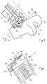
- FIG. 10 shows the arrangement according to FIG. 9, wherein additionally on the reference device 5 Moving device 10 is arranged, which one Base bar 10g and attached adapter parts 10h in Moving X and Y direction allowed.
- the Moving device 10 also as an adjusting device or to designate a feed device comprises one feed device 10e, which with a rack 10a is firmly connected.
- This rack 10a is partially in the longitudinal guide 5z arranged extending, the Gear 5x of the knurled screw 5v in the rack 10a engages around the rack 10a in the direction of displacement 10b, which corresponds to the X direction.
- the Feed device 10e has, analogously to that in the figures 2a to 2c shown reference device 5, a Knurled screw 10f, which is an invisible one Worm gear that drives one in one Gear arranged in a longitudinal guide through the Longitudinal guide guided rack 10c engages around this to move in the direction of displacement 10d.
- the 10 is the embodiment Direction of displacement 10d identical to the Y direction.
- the two axes of movement or displacement directions 10b, 10d preferably run at right angles to each other, can but also at a different angle to each other run.
- the reference device 5 could be the adjusting device 10 also be arranged on the mounting bracket 9, in which the Mounting bracket 9 a longitudinal guide 5z and a Knurled screw 5v for picking up and moving the rack 10a.
- Adjusting device 10 fastens a cutting jig 11, which slits running at different angles 11a has around the saw blade 12 with saw teeth 12a exactly at the angles predetermined by the implant to lead. 12 shows one with the saw blade 12 performed resection incision on the tibia front 2b. ever according to the embodiment of a knee joint prosthesis the angles of the resection cuts differ run. Therefore there are different cutting gauges 11 available, the appropriate cutting gauge 11 am Base beam 10g is attached.
- the cutting jig 11 has also bores 11b for guiding a drill for the Patella canal.
- the cutting jig 11 can by manual Turn the knurled screws 5v, 10f to the required Be driven.
- the cutting jig 11 move exactly parallel so that exactly parallel running resection surfaces on femur 1 and tibia 2 can be created.
- the racks 10a, 10c could be one Have scale, for example one on the surface engraved scale over which the traversed path is readable. This is especially true with a manual Procedure or a manual actuation of the Knurled screws 5v, 10f are an advantage.
- the possibility of one manual procedure has the advantage that the Device even if a computer or one fails Motor can still be operated, so that even in one such emergency situation a continuation of the operation is guaranteed.
- the knurled screws 5v, 10f are motor-driven.
- 14 schematically shows a drive device 17 according to the invention, which is connected to a computer 16 via a bidirectional data line 16c and is controlled by the latter.
- the drive device 17 comprises an electric motor 17d with a shaft 17c.
- An angle disk 17e and a sensor 17f for detecting the angle of rotation are arranged on this shaft 17c.
- the electric motor 17d is controlled by the computer 16 and the angle of rotation of the electric motor 17d is monitored by the computer 16 via the sensor signal 17f.
- the knurled screw 5v, 10f and the shaft 17c are connected to one another via a flexible shaft 17a, which has an adapter part 17b at both ends.
- the flexible shaft 17a is preferably made of a metal wire.
- the arrangement according to FIG. 14 has the following advantages: Bone surgery places the highest demands on sterility. Therefore, all objects that are close to the operating field must have sterile properties. It would take considerable effort to build a sterilizable electric motor, which could be arranged directly on the travel device 10.
- the use of a metal wire, for example spring steel wire has the advantage that the electric motor can be arranged, for example, one to two meters away from the operating field.
- the use of a spring steel wire string has the advantage of a high modulus of elasticity and a low hysteresis effect. Due to the greater distance from the operating field, there are fewer requirements with regard to the sterility of the drive device 17.
- the shaft 17a according to the invention also has the advantage that it can be sterilized and, since it is inexpensive to produce, can also be designed as a disposable product.
- the drive device 17 also has the advantage that the knurled screw 5v is both drivable and its angle of rotation can be monitored via the sensor 17f.
- the drive device 17 can also have a plurality of independent drives for flexible shafts 17a.
- the shaft 17a can be designed as a solid wire or as a hollow wire. Steel wires are preferably used, wires of other metals or of plastic or composite material also being suitable.
- the drive device 17 with an electric motor 17d, angle disk 17e and sensor 17f could be arranged in or in place of the knurled screw 5v, the drive device 17 being connected to a computer 16 via an electrical control and data line 16c.
- the Moving device 10 with a 14 driven in which the knurled screws 15v, 10f each with a shaft 17a are connected. It is not only possible with that Base bar 10g with attached adapter part 10h in X and Y direction, but also the Geometry of the condyle 1a at selected points as well to measure the tibia plateau.
- Base bar 10g with attached adapter part 10h in X and Y direction, but also the Geometry of the condyle 1a at selected points as well to measure the tibia plateau.
- the embodiment 10 is a guide 10k on the adapter part 10h a probe 101 with measuring tip 10n arranged.
- the Guide 10k is displaceable in the direction of 10m Adapter part stored for 10 hours.
- the geometry of a femoral condyle 1a can be measured, for example, as follows:
- the base bar 10g is initially moved without an adapter part 10h attached to it such that the base bar 10g comes into abutment with the femoral condyle 1a at the front of the femur 1.
- the position of the front of the femur 1 can thus be determined and stored by the computer 16.
- the base bar 10g is then moved away again and, as shown in FIG. 10, the adapter part 10h with probe 101 is arranged on the base bar 10g.
- the base bar 10g is then moved until the stylus tip 10n of the probe 101 reaches the illustrated support with the femur 1.
- the base bar 10g is moved away again, and a further measuring probe 101 is arranged for the guide 10k for the probe, which probe can be fastened with a knurled screw 10p.
- the measuring probe 101 is arranged eccentrically, the dorsal extent 1d of the condyle 1a can be measured by moving the base bar 10g.
- the probe 101 is arranged centrally, the depth of the pit 10b can be measured by moving the base bar 10g.
- the condyle can also be measured at several points by designing the probe accordingly.
- a scale extending in the longitudinal direction on the adapter part 10h is arranged , which allows the lateral position of the probe tip to be read, so that the total width of the femoral joint head can be determined on the basis of the measured, medial and lateral extension of the condyles 1a.
- This width can be entered into the computer by hand, for example, so that the computer has the geometric data of the femoral head available for further calculations.
- the measuring probes 101 can be used in many different ways be shaped to take into account the anatomical shape of the femur's surfacefaststasten.
- a probe 101 could also be like this be configured such that, similar to that in FIG. 11 shown, arranged on the guide 10k the dorsal Scanning area of the femur 1 allowed.
- the overall system for implanting a Total knee joint prosthesis included in a preferred Embodiment a computer or a computer with a screen.
- the coordinates of the location of the with the Measuring probes 101 determined measuring points of the condyles of the Femurs are the computer via the drive device 17 transmitted, the computer both the division of the Angle gear 17e as well as the gear ratio of Gear of the feed unit 10e is predetermined, so that the calculator the distances of the individual measuring points in absolute coordinates and preferably in the unit Can calculate millimeters.
- the computer Database with the geometric data available Knee joint implants saved using the calculator compares this data with the measured data and a proposes optimally fitting knee joint implant and this on the screen.
- Embodiment is shown on the screen as in Fig. 13a shown, the measured femur, the resection lines and the knee joint implant to be attached to the femur shown.
- the surgeon checks the presented Proposal and either confirms that proposal, shifts the resection lines in their entirety, or choose another one that seems more suitable to him Knee joint implant. After choosing the appropriate one
- the computer accesses a knee joint implant Database in which all geometric data of the Implant, especially the arrangement and the Course of the standard contact surfaces of the implant or the corresponding resection lines are stored. Based on this data, the computer determines which one a plurality of available cutting gauges 11 on the base bar 11g is to be attached to the previously determined cuts to do.
- a single cutting jig could 11 are provided, which are the angles of the respective Resection cut lines determined.
- their Cut line course on corresponding implants the resection lines on the femur according to the design and size of a each implant can be cut.
- the cutting jig 11 becomes the traversing device 10 controlled by the computer so that the cutting template 11 is moved into the first cutting position.
- the surgeon can Saw blade 12 in the respective slot 11a of the gauge 11 insert and make the cut.
- the device according to the invention it also enables a less experienced person Surgeons the femur 1 and the tibia 2 easily, exactly to cut and insert the implant.
- Figures 13a, 13b, 13c disclose an overall system for Inserting a knee prosthesis that does not have a cutting jig 11 Requires more because the location of the sawing device 14 and thus the position of the saw blade 12 directly from the Moving device 10 is controlled and determined.
- a rotary adjustment device 13q which is designed as a latching device 13a, is arranged on the base bar 10g of the displacement device 10.
- This latching device 13a has latching points 13n arranged distributed over its circumference, each latching point 13n defining a fixedly predetermined pivoting angle of the arm 13c in the pivoting direction 13m.
- a knurled screw 13b allows the screw shaft 13o to be raised or lowered.
- the rotary adjustment device 13q could also have a motor drive instead of the latching device 13a, which allows a predeterminable angle of rotation to be set.
- Such a motor-driven rotary adjustment device 13q preferably also comprises a rotation angle sensor which detects the angle of rotation, so that the angle to be taken up of the rotary adjustment device 13q can be specified, for example, with the aid of a control device or a computer.
- the arm 13c is connected to a second arm 13f via a joint which is movable in the direction of movement 13d and which is in turn connected to the third arm 13h via a joint which is movable in the direction of movement 13g.
- the third arm 13h forms an axial attachment 13i for the sawing device 14 on the one hand and a guide 13k with a slot 131 for the saw blade 12 on the other hand to pivot.
- the saw blade 12 forms a saw blade level and is slidably mounted in this plane.
- the arm 13 can be designed in such a way that it has a spring force, so that an increasing restoring force on the sawing device 14 is brought about when the saw blade 12 is fed to the condyle 1a.
- torsion springs could be arranged in the joints of the arm 13, for example.
- the guide 13k is firmly connected to the arm 13h.
- the guide 13k could also be articulated on the arm 13h via a joint, so that the guide 13k is pivotally mounted for fastening 13i. This measure allows the saw blade 12 to penetrate deeper into the body to be cut.
- the sawing device 14 has a handle 14a, which, in order to decrease too much by the Operation of caused moments with regard to the holding arm 13 is pivotable in the direction 14g about the axis 14h.
- the Handle 14a could also about an axis of rotation 13p be pivoted.
- the handle 14a thus serves the movement initiation in direction 14c and in Swivel direction 14d about the axis 13p. This is the location of the handle 14a in the vertical pivoting direction regardless of the position of the saw blade 12.
- the Inclination of the holding arm 13 with respect to the base bar 10g is, as shown in Fig. 13c, by rotating the arm 13c possible about the axis of rotation 13e of the latching device.
- the position of the saw blade 12 by the Computer 16 controlled moving device 10 determines.
- the guide 13k is preferably designed with a slot 131 around the relatively thin saw blade 12 to lead in a defined position, and to a Avoid bending the saw blade 12.
- the Holding arm 13 together with the saw device 14 relative large forces on the moving device 10 or Base plate 3 could impact is in the with Fig. 13a embodiment shown a frame 15th provided that a cable winding device 14f includes and a rope 14e, which has the task of a at least the gravity of the sawing device 14 to generate compensating counterforce F.
- the frame 15 includes a boom 15a, a vertical rod 15b Assumed 15c and wheels 15d.
- the frame 15 On the frame 15 is also the supply and discharge line 14b for driving the sawing device 14 arranged.
- the computer 16 with a screen 16a and keyboard 16b attached to the frame 15.
- the drive device 17 attached to the frame 15, wherein the two knurled screws 5v, 10f over the flexible shaft 17a are driven by the drive device 17.
- the holding arm 13 shown could also be such be configured such that it has sensors which the angles in the direction of movement 13d, 13g and 13m too Allow to grasp the exact position of the saw blade 12 to grasp or in place of a saw blade 12 arranged probe the position and geometry of the condyle 1a measure.
- FIGS 16a to 16d disclose another Embodiment of an anchorable on the femur 1 Base plate 3 or a base device 3.
- This Base device 3 includes a base platform 3h Longitudinal axis 3s, on which four can be displaced in the direction 31 supported legs 3i, 3k are arranged. The legs 3i, 3k are displaceable on grooves 3o running in the direction 31 stored.
- a shaft 3n with an external thread engages Internal thread of the legs 3i, 3k.
- the shaft 3n has one 3p screw head accessible from the side.
- the thread in Leg 3i is a left-hand thread, the thread in leg 3k is Right-hand thread designed, the thread of the shaft 3n is adapted accordingly to the intervention.
- the shaft 3n has one in the middle cylindrical, the diameter of the shaft 3n exceeding section 3m, which in one Gap 3r of the base platform 3h is arranged, and which in the direction of displacement 31 on both sides with little Game rests on the base platform 3h and thereby the Position of the shaft 3n with respect to the base platform 3h in Direction 31 defines and therefore as a centering element 3m serves.
- 16b shows two in a side view opposite legs 3i, 3k, which on the opposite inner surfaces in the direction of displacement 31 have protruding tips 3q, which for penetration into the femur 1 are determined.
- the base device 3 is attached to the femur 1 in such a way that this is initially in the direction of the femur axis 19a is placed on the femur 1 and then the opposite legs 3i, 3k by rotating the shaft 3n be brought closer together until the peaks 3q in the Femur 1 penetrate and the base device 3 with safely the femur 1 is connected.
- the shaft 3n is configured on both sides Screw head 3p on, so that the shaft 3n optionally from one of the two legs 3i, 3k can be actuated.
- Base device 3 can be seen in that after the Attach to the femur 1 in the direction of the femur axis 19a or in the direction of the intramedular cavity of the femur 1.
- the base device 3 thus has an intramedular course, but without one to use intramedially arranged body.
- the two recesses 3b, 3f are similar to that in FIG Base plate 3 designed according to FIG. 1a and are used for Attach the reference body 5 by means of a Bayonet catch.
- 16c shows a top view of the Arrangement of the recesses 3b, 3f on the base platform 3h.
- the two lower recesses 3b, 3f define one Straight 19b, which is through the center of the base platform 3h straight line 19a, 3s at an angle ⁇ cuts. This angle ⁇ is preferably in the range of 6 ⁇ 2 degrees.
- the straight line 19a corresponds to the Femur 1 attached base device 3 the course of the Anatomical axis 19a of the femur 1.
- the Base device 3 has two pairs of recesses 3b, 3f on, the one arranged above the straight line 19a, 3s Pair, as shown in Fig. 16d, at the femur 1 one right leg is used, whereas the lower pair is to be used for femur 1 of a left leg in order to predetermined anatomical axis 19a of the femur 1 den Approximately specify the course of the load axis 19b.
Landscapes
- Health & Medical Sciences (AREA)
- Surgery (AREA)
- Life Sciences & Earth Sciences (AREA)
- Biomedical Technology (AREA)
- Medical Informatics (AREA)
- Oral & Maxillofacial Surgery (AREA)
- Nuclear Medicine, Radiotherapy & Molecular Imaging (AREA)
- Transplantation (AREA)
- Physical Education & Sports Medicine (AREA)
- Engineering & Computer Science (AREA)
- Orthopedic Medicine & Surgery (AREA)
- Heart & Thoracic Surgery (AREA)
- Dentistry (AREA)
- Molecular Biology (AREA)
- Animal Behavior & Ethology (AREA)
- General Health & Medical Sciences (AREA)
- Public Health (AREA)
- Veterinary Medicine (AREA)
- Prostheses (AREA)
- Surgical Instruments (AREA)
Claims (21)
- Dispositif pour la détermination et la réalisation de coupes de résection sur le fémur (1) pour préparer une implantation d'une endoprothèse totale de l'articulation du genou, comprenant :caractérisé en ce que :un dispositif de référence (5) pouvant être bloqué dans la région distale du fémur (1) avec possibilité de détachement et dont l'orientation par rapport au fémur (1) peut être positionnée exactement ; etun dispositif de réglage (10), relié au dispositif de référence (5) et réglable par rapport à celui-ci, qui présente une partie de base (10g) réglable linéairement pour fixer un instrument (11, 14, 101),le dispositif de réglage (10) est déplaçable linéairement en direction (10b) d'un premier axe (x) d'un système de coordonnées (X, Y, Z) défini par le dispositif de référence, au moyen d'un premier dispositif d'entraínement (5v, 17) présentant un entraínement motorisé (17d) ; etla partie de base (10g) est réglable linéairement en direction (10d) d'un second axe (y) du système de coordonnées (X, Y, Z), au moyen d'un second dispositif d'entraínement (10f, 17) présentant un entraínement motorisé (17d).
- Dispositif selon la revendication 1, caractérisé en ce qu'aussi bien le premier que le second dispositif d'entraínement (5v, 17 ; 10f, 17) présentent un entraínement par moteur électrique.
- Dispositif selon la revendication 1 ou 2, caractérisé en ce que les entraínements motorisés (17d) sont commandés par un calculateur (16) auquel sont associés de préférence un écran (16a) et un clavier de saisie (16b).
- Dispositif selon la revendication 1, caractérisé en ce que le dispositif de référence (5) définit au moins le premier axe (x) du système de coordonnées (X, Y, Z), ce premier axe (x) s'étendant essentiellement en direction de l'axe de sollicitation (19b) du fémur (1) lorsque le dispositif de référence (5) est orienté par rapport au fémur (1).
- Dispositif selon la revendication 4, caractérisé en ce que le dispositif de réglage (10) définit le second axe (y) du système de coordonnées (X, Y, Z), le premier et le second axe (x, y) s'étendant perpendiculairement l'un à l'autre et définissant un plan dans lequel se trouve essentiellement l'axe de sollicitation (19b) du fémur (1).
- Dispositif selon l'une des revendications 1 à 5, caractérisé en ce que :le dispositif de référence (5) présente un guidage linéaire (5z) s'étendant en direction (10b) du premier axe (x) du système de coordonnées (X, Y, Z) ;le dispositif de réglage (10) comporte une tige adaptée au guidage linéaire (5z) et mobile dans la direction mentionnée (10b) du premier axe (x) du système de coordonnées (X, Y, Z), ladite tige étant réalisée en particulier comme tige à crémaillère (10a) ; etle premier dispositif d'entraínement (5v, 17) agit sur la tige (10a) et permet un déplacement de la tige (10a) par rapport au dispositif de référence (5).
- Dispositif selon l'une des revendications 1 à 6, caractérisé en ce que le premier dispositif d'entraínement (5v, 17) ou le second dispositif d'entraínement (10f, 17) est agencé soit directement sur le dispositif de référence (5), soit directement sur le dispositif de réglage (10), ou est agencé à une certaine distance par rapport au dispositif de référence (5) ou au dispositif de réglage (10), et est relié fonctionnellement au dispositif de référence (5) ou au dispositif de réglage (10) via un arbre flexible (17a).
- Dispositif selon l'une des revendications 1 à 7, caractérisé en ce qu'au moins un capteur de mesure (101) peut être fixé de manière détachable sur la partie de base (10g) du dispositif de réglage (10) pour explorer la position des condyles (1a) du fémur (1).
- Dispositif selon l'une des revendications 1 à 7, caractérisé en ce qu'un dispositif de coupe (11, 14), en particulier un gabarit de coupe (11), est fixé sur la partie de base (10g) du dispositif de réglage (10) pour guider une lame de scie (12) ou un dispositif de sciage (14) comportant une lame de scie (12).
- Dispositif selon la revendication 9, caractérisé en ce que :la lame de scie (12) du dispositif de sciage (14) définit un plan de lame de scie ;le dispositif de sciage (14) est fixé sur la partie de base (10g) du dispositif de réglage (10) avec un moyen de liaison (13) ; etle moyen de liaison (13) ainsi que le dispositif de sciage (14) sont réalisés de sorte que la lame de scie (12) est montée mobile en translation exclusivement dans le plan de la lame de scie.
- Dispositif selon la revendication 10, caractérisé en ce que le moyen de liaison (13) est réalisé comme un bras pivotant (13f, 13h) ou comme un guidage télescopique à deux axes.
- Dispositif selon la revendication 10 ou 11, caractérisé en ce qu'une poignée (14a) est montée avec articulation sur le dispositif de sciage (14) de sorte que la position de la poignée (14a) dans l'espace n'influe pas sur l'orientation de la lame de scie (12) par rapport au plan de coupe.
- Dispositif selon l'une des revendications 10 à 12, caractérisé en ce que le moyen de liaison (13) est relié à la partie de base (10g) du dispositif de réglage (10) via un dispositif de réglage rotatif (13q) présentant un axe de rotation (13e) et en ce que le dispositif de réglage rotatif (13q) permet un pivotement d'un angle de rotation (13m) du moyen de liaison (13) par rapport au dispositif de réglage (10).
- Dispositif selon la revendication 13, caractérisé en ce que le dispositif de réglage rotatif est réalisé comme un dispositif à enclenchement mécanique (13q) qui présente des éléments de blocage (13b , 13o) pour bloquer l'angle de rotation de l'axe de rotation (13e) dans des positions prédéterminées.
- Dispositif selon la revendication 13, caractérisé en ce que le dispositif de réglage rotatif (13q) comporte un entraínement motorisé qui permet d'ajuster un angle de rotation pouvant être prescrit, et en ce que le dispositif de réglage rotatif (13q) comporte de préférence un capteur d'angle de rotation pour saisir l'angle de rotation.
- Dispositif selon l'une des revendications 1 à 15, caractérisé en ce qu'il est prévu une pièce d'ancrage (3) qui peut être fixée fermement au fémur (1), et en ce que la pièce d'ancrage (3) forme, conjointement avec le dispositif de référence (5), une fermeture détachable qui est réalisée en particulier comme fermeture à baïonnette.
- Dispositif selon l'une des revendications 1 à 16, caractérisé en ce que :le dispositif de référence (5) présente une partie de base (5a) pouvant être bloquée de façon détachable dans la région distale du fémur (1) ainsi qu'un corps de référence (50) relié à la partie de base (5a) de préférence avec articulation et/ou mobile en translation et dont l'orientation par rapport au fémur (1) peut être positionnée exactement ; etil est prévu un moyen d'actionnement (5l, 5r) agissant entre le corps de référence (50) et la partie de base (5a) pour fixer leur position réciproque.
- Dispositif selon la revendication 17, caractérisé en ce que, par rapport au corps de référence (50), la partie de base (5a) est montée avec faculté de pivotement au moins autour d'un axe (5i) s'étendant essentiellement en direction de l'axe de sollicitation (19b) du fémur (1) lorsque la partie de base (5a) est bloquée sur le fémur (1).
- Dispositif selon la revendication 16, caractérisé en ce que la pièce d'ancrage (3) présente un soutien à trois points (3a) qui est destiné à l'appui sur le fémur (1).
- Dispositif selon la revendication 16 ou 17, caractérisé en ce que :la pièce d'ancrage (3) comporte une plate-forme de base (3h) comprenant un axe longitudinal (3 s) ;au moins deux plaquettes (3k, 3i) sont montées mobiles en translation par rapport à la plate-forme de base (3h) et sont agencées à l'opposé approximativement perpendiculairement à l'axe longitudinal (3s) ; etles plaquettes (3k, 3i) présentent des pointes (3q) qui dépassent, qui sont agencées en s'étendant avec orientation vers le fémur (1) et qui sont destinées à pénétrer dans l'os du fémur.
- Dispositif selon l'une des revendications 1 à 20, caractérisé en ce qu'une barre d'orientation (7) est montée sur le corps de référence (50), en s'étendant en direction d'un axe (x) du système de coordonnées (X, Y, Z) et avec faculté de rotation autour d'un axe de rotation s'étendant en direction d'un troisième axe (z) du système de coordonnées (X, Y, Z).
Applications Claiming Priority (1)
| Application Number | Priority Date | Filing Date | Title |
|---|---|---|---|
| PCT/CH1998/000280 WO2000000093A1 (fr) | 1998-06-29 | 1998-06-29 | Dispositif et procede pour inserer une prothese du genou |
Publications (2)
| Publication Number | Publication Date |
|---|---|
| EP1091696A1 EP1091696A1 (fr) | 2001-04-18 |
| EP1091696B1 true EP1091696B1 (fr) | 2004-09-08 |
Family
ID=4551341
Family Applications (1)
| Application Number | Title | Priority Date | Filing Date |
|---|---|---|---|
| EP98928043A Expired - Lifetime EP1091696B1 (fr) | 1998-06-29 | 1998-06-29 | Dispositif pour inserer une prothese du genou |
Country Status (9)
| Country | Link |
|---|---|
| US (1) | US6554837B1 (fr) |
| EP (1) | EP1091696B1 (fr) |
| JP (1) | JP2002519093A (fr) |
| CN (1) | CN1245928C (fr) |
| AT (1) | ATE275367T1 (fr) |
| AU (1) | AU755664B2 (fr) |
| DE (1) | DE59811929D1 (fr) |
| ES (1) | ES2224406T3 (fr) |
| WO (1) | WO2000000093A1 (fr) |
Cited By (1)
| Publication number | Priority date | Publication date | Assignee | Title |
|---|---|---|---|---|
| CN102119869A (zh) * | 2011-03-21 | 2011-07-13 | 潍坊航维医疗器械有限公司 | 股骨颈专用钻孔定位器 |
Families Citing this family (232)
| Publication number | Priority date | Publication date | Assignee | Title |
|---|---|---|---|---|
| US5778367A (en) * | 1995-12-14 | 1998-07-07 | Network Engineering Software, Inc. | Automated on-line information service and directory, particularly for the world wide web |
| US11026768B2 (en) | 1998-10-08 | 2021-06-08 | Align Technology, Inc. | Dental appliance reinforcement |
| US6928742B2 (en) | 2000-08-31 | 2005-08-16 | Plus Orthopedics Ag | Method and apparatus for finding the position of a mechanical axis of a limb |
| FR2813780A1 (fr) * | 2000-09-08 | 2002-03-15 | Biomet Merck France | Procede et materiel ancillaire de determination d'au moins un point de l'interligne articulaire theorique d'un genou |
| FR2816200A1 (fr) | 2000-11-06 | 2002-05-10 | Praxim | Determination de la position d'une prothese du genou |
| US7547307B2 (en) * | 2001-02-27 | 2009-06-16 | Smith & Nephew, Inc. | Computer assisted knee arthroplasty instrumentation, systems, and processes |
| US7909831B2 (en) * | 2001-02-28 | 2011-03-22 | Howmedica Osteonics Corp. | Systems used in performing femoral and tibial resection in knee surgery |
| KR20030002219A (ko) * | 2001-06-30 | 2003-01-08 | 한국과학기술원 | 고관절수술로봇을 위한 대퇴골 고정식 로봇설치대 |
| DE10141323B4 (de) * | 2001-08-28 | 2006-06-14 | Fraunhofer-Gesellschaft zur Förderung der angewandten Forschung e.V. | Vorrichtung zur räumlichen Positionierung eines Werkzeuges relativ zum menschlichen oder tierischen Knochenapparat im Gelenkbereich |
| US7618421B2 (en) | 2001-10-10 | 2009-11-17 | Howmedica Osteonics Corp. | Tools for femoral resection in knee surgery |
| CA2475979A1 (fr) * | 2002-02-11 | 2003-08-21 | Smith & Nephew, Inc. | Reduction de fracture guidee par image |
| EP1501438B1 (fr) * | 2002-04-30 | 2011-11-16 | Orthosoft Inc. | Determination des decoupes femorales en chirurgie du genou |
| DE10306793A1 (de) * | 2002-05-21 | 2003-12-04 | Plus Endoprothetik Ag Rotkreuz | Anordnung und Verfahren zur intraoperativen Festlegung der Lage eines Gelenkersatzimplantats |
| US8211113B2 (en) * | 2002-06-21 | 2012-07-03 | Depuy Products, Inc. | Prosthesis cutting guide, cutting tool and method |
| US7935118B2 (en) * | 2002-06-21 | 2011-05-03 | Depuy Products, Inc. | Prosthesis removal cutting guide, cutting tool and method |
| US20030236522A1 (en) * | 2002-06-21 | 2003-12-25 | Jack Long | Prosthesis cavity cutting guide, cutting tool and method |
| GB0219342D0 (en) * | 2002-08-20 | 2002-09-25 | Depuy Int Ltd | A guide block for use in surgery |
| DE10239673A1 (de) * | 2002-08-26 | 2004-03-11 | Markus Schwarz | Vorrichtung zur Bearbeitung von Teilen |
| US7094241B2 (en) | 2002-11-27 | 2006-08-22 | Zimmer Technology, Inc. | Method and apparatus for achieving correct limb alignment in unicondylar knee arthroplasty |
| US7029477B2 (en) * | 2002-12-20 | 2006-04-18 | Zimmer Technology, Inc. | Surgical instrument and positioning method |
| US20070282347A9 (en) * | 2002-12-20 | 2007-12-06 | Grimm James E | Navigated orthopaedic guide and method |
| US20040172044A1 (en) * | 2002-12-20 | 2004-09-02 | Grimm James E. | Surgical instrument and method of positioning same |
| US7887542B2 (en) | 2003-01-15 | 2011-02-15 | Biomet Manufacturing Corp. | Method and apparatus for less invasive knee resection |
| US7789885B2 (en) | 2003-01-15 | 2010-09-07 | Biomet Manufacturing Corp. | Instrumentation for knee resection |
| US8551100B2 (en) | 2003-01-15 | 2013-10-08 | Biomet Manufacturing, Llc | Instrumentation for knee resection |
| US7837690B2 (en) | 2003-01-15 | 2010-11-23 | Biomet Manufacturing Corp. | Method and apparatus for less invasive knee resection |
| US20040153066A1 (en) * | 2003-02-03 | 2004-08-05 | Coon Thomas M. | Apparatus for knee surgery and method of use |
| US6865954B2 (en) * | 2003-03-10 | 2005-03-15 | Spinecore, Inc. | Joint simulator testing machine |
| GB0313445D0 (en) * | 2003-06-11 | 2003-07-16 | Midland Medical Technologies L | Hip resurfacing |
| FR2856274B1 (fr) * | 2003-06-18 | 2007-11-02 | Perception Raisonnement Action | Dispositif de positionnement de guide de coupe osseuse |
| FR2856268B1 (fr) * | 2003-06-18 | 2005-10-21 | Perception Raisonnement Action | Dispositif de guidage de coupe osseuse |
| DE50309180D1 (de) * | 2003-09-13 | 2008-03-27 | Aesculap Ag & Co Kg | Vorrichtung zur bestimmung des winkels zwischen femur und tibia |
| US7862570B2 (en) | 2003-10-03 | 2011-01-04 | Smith & Nephew, Inc. | Surgical positioners |
| CA2538126A1 (fr) * | 2003-10-06 | 2005-05-06 | Smith & Nephew, Inc. | Portail a navigation modulaire |
| US7764985B2 (en) | 2003-10-20 | 2010-07-27 | Smith & Nephew, Inc. | Surgical navigation system component fault interfaces and related processes |
| EP1691692B1 (fr) * | 2003-11-14 | 2011-01-19 | Smith & Nephew, Inc. | Systemes coupants ajustables de chirurgie |
| EP1696807B1 (fr) | 2003-11-18 | 2009-09-30 | Smith & Nephew, Inc. | Technique chirurgicale et instrumentation pour une chirurgie de la hanche par arthroplastie avec incision minimale |
| US8657824B2 (en) * | 2003-11-18 | 2014-02-25 | Smith & Nephew, Inc. | Universal double offset surgical instrument |
| US7488324B1 (en) | 2003-12-08 | 2009-02-10 | Biomet Manufacturing Corporation | Femoral guide for implanting a femoral knee prosthesis |
| US7641661B2 (en) | 2003-12-26 | 2010-01-05 | Zimmer Technology, Inc. | Adjustable resection guide |
| US9492245B2 (en) | 2004-02-27 | 2016-11-15 | Align Technology, Inc. | Method and system for providing dynamic orthodontic assessment and treatment profiles |
| US7993341B2 (en) | 2004-03-08 | 2011-08-09 | Zimmer Technology, Inc. | Navigated orthopaedic guide and method |
| US8114086B2 (en) * | 2004-03-08 | 2012-02-14 | Zimmer Technology, Inc. | Navigated cut guide locator |
| US7641660B2 (en) * | 2004-03-08 | 2010-01-05 | Biomet Manufacturing Corporation | Method, apparatus, and system for image guided bone cutting |
| WO2005104978A1 (fr) | 2004-04-21 | 2005-11-10 | Smith & Nephew, Inc. | Procedes, systemes et appareils assistes par ordinateur pour arthroplastie de l'epaule |
| US7219555B2 (en) * | 2004-05-03 | 2007-05-22 | Salvesen William R | Method and apparatus for testing a joint replacement device |
| US8167888B2 (en) * | 2004-08-06 | 2012-05-01 | Zimmer Technology, Inc. | Tibial spacer blocks and femoral cutting guide |
| EP1669033B1 (fr) * | 2004-12-08 | 2009-02-18 | Perception Raisonnement Action En Medecine | Dispositif de positionnement d'un guide de coupe osseuse |
| US20060200158A1 (en) * | 2005-01-29 | 2006-09-07 | Farling Toby N | Apparatuses and methods for arthroplastic surgery |
| AU2006216653B2 (en) | 2005-02-22 | 2012-03-15 | Smith & Nephew, Inc. | In-line milling system |
| WO2006106419A2 (fr) * | 2005-04-07 | 2006-10-12 | Perception Raisonnement Action En Medecine | Ensemble de guidage robotique conçu pour etre utilise dans des applications de chirurgie assistee par ordinateur |
| US7695479B1 (en) | 2005-04-12 | 2010-04-13 | Biomet Manufacturing Corp. | Femoral sizer |
| FR2885293A1 (fr) * | 2005-05-06 | 2006-11-10 | Michel Collette | Instrument de viseee de l'axe mecanique du femur |
| US20070073136A1 (en) * | 2005-09-15 | 2007-03-29 | Robert Metzger | Bone milling with image guided surgery |
| US20070149977A1 (en) * | 2005-11-28 | 2007-06-28 | Zimmer Technology, Inc. | Surgical component positioner |
| US7744600B2 (en) * | 2006-01-10 | 2010-06-29 | Zimmer Technology, Inc. | Bone resection guide and method |
| US7780671B2 (en) | 2006-01-23 | 2010-08-24 | Zimmer Technology, Inc. | Bone resection apparatus and method for knee surgery |
| US20070233138A1 (en) * | 2006-01-27 | 2007-10-04 | Zimmer Technology, Inc. | Apparatuses and methods for arthroplastic surgery |
| US20070186738A1 (en) * | 2006-01-31 | 2007-08-16 | Zimmer Technology, Inc. | Tibial cut guide assembly having rotatable cut guide body |
| US8608749B2 (en) | 2006-02-27 | 2013-12-17 | Biomet Manufacturing, Llc | Patient-specific acetabular guides and associated instruments |
| US8858561B2 (en) | 2006-06-09 | 2014-10-14 | Blomet Manufacturing, LLC | Patient-specific alignment guide |
| US9907659B2 (en) | 2007-04-17 | 2018-03-06 | Biomet Manufacturing, Llc | Method and apparatus for manufacturing an implant |
| US8864769B2 (en) | 2006-02-27 | 2014-10-21 | Biomet Manufacturing, Llc | Alignment guides with patient-specific anchoring elements |
| US9339278B2 (en) | 2006-02-27 | 2016-05-17 | Biomet Manufacturing, Llc | Patient-specific acetabular guides and associated instruments |
| US10278711B2 (en) | 2006-02-27 | 2019-05-07 | Biomet Manufacturing, Llc | Patient-specific femoral guide |
| US8377066B2 (en) | 2006-02-27 | 2013-02-19 | Biomet Manufacturing Corp. | Patient-specific elbow guides and associated methods |
| US9918740B2 (en) | 2006-02-27 | 2018-03-20 | Biomet Manufacturing, Llc | Backup surgical instrument system and method |
| US7780672B2 (en) | 2006-02-27 | 2010-08-24 | Biomet Manufacturing Corp. | Femoral adjustment device and associated method |
| US8298237B2 (en) | 2006-06-09 | 2012-10-30 | Biomet Manufacturing Corp. | Patient-specific alignment guide for multiple incisions |
| US8092465B2 (en) | 2006-06-09 | 2012-01-10 | Biomet Manufacturing Corp. | Patient specific knee alignment guide and associated method |
| US7967868B2 (en) | 2007-04-17 | 2011-06-28 | Biomet Manufacturing Corp. | Patient-modified implant and associated method |
| US9173661B2 (en) | 2006-02-27 | 2015-11-03 | Biomet Manufacturing, Llc | Patient specific alignment guide with cutting surface and laser indicator |
| US8282646B2 (en) | 2006-02-27 | 2012-10-09 | Biomet Manufacturing Corp. | Patient specific knee alignment guide and associated method |
| US9113971B2 (en) | 2006-02-27 | 2015-08-25 | Biomet Manufacturing, Llc | Femoral acetabular impingement guide |
| US8241293B2 (en) | 2006-02-27 | 2012-08-14 | Biomet Manufacturing Corp. | Patient specific high tibia osteotomy |
| US8535387B2 (en) | 2006-02-27 | 2013-09-17 | Biomet Manufacturing, Llc | Patient-specific tools and implants |
| US9289253B2 (en) | 2006-02-27 | 2016-03-22 | Biomet Manufacturing, Llc | Patient-specific shoulder guide |
| US8070752B2 (en) | 2006-02-27 | 2011-12-06 | Biomet Manufacturing Corp. | Patient specific alignment guide and inter-operative adjustment |
| US8608748B2 (en) | 2006-02-27 | 2013-12-17 | Biomet Manufacturing, Llc | Patient specific guides |
| US8133234B2 (en) | 2006-02-27 | 2012-03-13 | Biomet Manufacturing Corp. | Patient specific acetabular guide and method |
| US9345548B2 (en) | 2006-02-27 | 2016-05-24 | Biomet Manufacturing, Llc | Patient-specific pre-operative planning |
| US8591516B2 (en) | 2006-02-27 | 2013-11-26 | Biomet Manufacturing, Llc | Patient-specific orthopedic instruments |
| US20150335438A1 (en) | 2006-02-27 | 2015-11-26 | Biomet Manufacturing, Llc. | Patient-specific augments |
| US9730616B2 (en) * | 2008-10-22 | 2017-08-15 | Biomet Manufacturing, Llc | Mechanical axis alignment using MRI imaging |
| US8568487B2 (en) | 2006-02-27 | 2013-10-29 | Biomet Manufacturing, Llc | Patient-specific hip joint devices |
| US8407067B2 (en) | 2007-04-17 | 2013-03-26 | Biomet Manufacturing Corp. | Method and apparatus for manufacturing an implant |
| US8603180B2 (en) | 2006-02-27 | 2013-12-10 | Biomet Manufacturing, Llc | Patient-specific acetabular alignment guides |
| US8473305B2 (en) | 2007-04-17 | 2013-06-25 | Biomet Manufacturing Corp. | Method and apparatus for manufacturing an implant |
| US7695520B2 (en) | 2006-05-31 | 2010-04-13 | Biomet Manufacturing Corp. | Prosthesis and implementation system |
| US9795399B2 (en) | 2006-06-09 | 2017-10-24 | Biomet Manufacturing, Llc | Patient-specific knee alignment guide and associated method |
| DE102006035602A1 (de) * | 2006-07-31 | 2008-02-07 | Plus Orthopedics Ag | Klammer zur Befestigung chirurgischer Operationshilfsmittel, Stellorgan für eine derartige Klammer und eine Anordnung umfassend ein Stellorgan und eine Klammer |
| US20080140081A1 (en) * | 2006-12-04 | 2008-06-12 | Zimmer, Inc. | Cut guides |
| US8214016B2 (en) * | 2006-12-12 | 2012-07-03 | Perception Raisonnement Action En Medecine | System and method for determining an optimal type and position of an implant |
| US7878805B2 (en) | 2007-05-25 | 2011-02-01 | Align Technology, Inc. | Tabbed dental appliance |
| US8486079B2 (en) * | 2007-09-11 | 2013-07-16 | Zimmer, Inc. | Method and apparatus for remote alignment of a cut guide |
| US8265949B2 (en) | 2007-09-27 | 2012-09-11 | Depuy Products, Inc. | Customized patient surgical plan |
| US8357111B2 (en) | 2007-09-30 | 2013-01-22 | Depuy Products, Inc. | Method and system for designing patient-specific orthopaedic surgical instruments |
| US9138239B2 (en) | 2007-09-30 | 2015-09-22 | DePuy Synthes Products, Inc. | Customized patient-specific tibial cutting blocks |
| ES2838598T3 (es) * | 2007-09-30 | 2021-07-02 | Depuy Products Inc | Instrumento quirúrgico ortopédico personalizado y específico del paciente |
| US9173662B2 (en) | 2007-09-30 | 2015-11-03 | DePuy Synthes Products, Inc. | Customized patient-specific tibial cutting blocks |
| US8738394B2 (en) | 2007-11-08 | 2014-05-27 | Eric E. Kuo | Clinical data file |
| US8108189B2 (en) | 2008-03-25 | 2012-01-31 | Align Technologies, Inc. | Reconstruction of non-visible part of tooth |
| US8092215B2 (en) | 2008-05-23 | 2012-01-10 | Align Technology, Inc. | Smile designer |
| US9492243B2 (en) * | 2008-05-23 | 2016-11-15 | Align Technology, Inc. | Dental implant positioning |
| US8172569B2 (en) | 2008-06-12 | 2012-05-08 | Align Technology, Inc. | Dental appliance |
| AU2009262113A1 (en) | 2008-06-25 | 2009-12-30 | Small Bone Innovations, Inc. | Surgical instrumentation and methods of use for implanting a prothesis |
| US8152518B2 (en) | 2008-10-08 | 2012-04-10 | Align Technology, Inc. | Dental positioning appliance having metallic portion |
| DE102008052680A1 (de) * | 2008-10-22 | 2010-04-29 | Surgitaix Ag | Vorrichtung zur kontrollierten Einstellung einer chirurgischen Positioniereinheit |
| US9033958B2 (en) * | 2008-11-11 | 2015-05-19 | Perception Raisonnement Action En Medecine | Surgical robotic system |
| US8170641B2 (en) | 2009-02-20 | 2012-05-01 | Biomet Manufacturing Corp. | Method of imaging an extremity of a patient |
| US8292617B2 (en) | 2009-03-19 | 2012-10-23 | Align Technology, Inc. | Dental wire attachment |
| US9168106B2 (en) * | 2009-05-05 | 2015-10-27 | Blue Ortho | Device and method for instrument adjustment in computer assisted surgery |
| GB0909121D0 (en) * | 2009-05-28 | 2009-07-01 | Depuy Int Ltd | Bone cutting assembly |
| AP2011006002A0 (en) * | 2009-06-24 | 2011-12-31 | Custom Med Orthopaedics Proprietary Ltd | A positioning guide and a femur bone cutting guidesystem. |
| US8765031B2 (en) | 2009-08-13 | 2014-07-01 | Align Technology, Inc. | Method of forming a dental appliance |
| US8876830B2 (en) * | 2009-08-13 | 2014-11-04 | Zimmer, Inc. | Virtual implant placement in the OR |
| DE102009028503B4 (de) | 2009-08-13 | 2013-11-14 | Biomet Manufacturing Corp. | Resektionsschablone zur Resektion von Knochen, Verfahren zur Herstellung einer solchen Resektionsschablone und Operationsset zur Durchführung von Kniegelenk-Operationen |
| EP2538853A4 (fr) | 2010-02-25 | 2016-07-27 | Depuy Products Inc | Blocs de coupe osseuse spécifiques à un patient personnalisés |
| EP2538864B1 (fr) | 2010-02-25 | 2018-10-31 | DePuy Products, Inc. | Blocs de coupe osseuse spécifiques à un patient personnalisés |
| WO2011106407A1 (fr) | 2010-02-25 | 2011-09-01 | Depuy Products, Inc. | Procédé de fabrication de blocs de coupe osseuse spécifiques à un patient personnalisés |
| US8632547B2 (en) | 2010-02-26 | 2014-01-21 | Biomet Sports Medicine, Llc | Patient-specific osteotomy devices and methods |
| US9066727B2 (en) | 2010-03-04 | 2015-06-30 | Materialise Nv | Patient-specific computed tomography guides |
| US9241774B2 (en) | 2010-04-30 | 2016-01-26 | Align Technology, Inc. | Patterned dental positioning appliance |
| US9211166B2 (en) | 2010-04-30 | 2015-12-15 | Align Technology, Inc. | Individualized orthodontic treatment index |
| US8617170B2 (en) * | 2010-09-29 | 2013-12-31 | DePuy Synthes Products, LLC | Customized patient-specific computer controlled cutting system and method |
| US9271744B2 (en) | 2010-09-29 | 2016-03-01 | Biomet Manufacturing, Llc | Patient-specific guide for partial acetabular socket replacement |
| US8758354B2 (en) | 2010-10-22 | 2014-06-24 | Zimmer, Inc. | Flexible attachment for an extramedullary surgical instrument |
| WO2012058353A1 (fr) * | 2010-10-29 | 2012-05-03 | The Cleveland Clinic Foundation | Système et procédé pour aider à la présentation d'un instrument de série par rapport au tissu d'un patient |
| US9968376B2 (en) | 2010-11-29 | 2018-05-15 | Biomet Manufacturing, Llc | Patient-specific orthopedic instruments |
| CH704563B1 (de) * | 2011-02-21 | 2015-04-30 | Microport Orthopedics Inc | Patientenspezifischer Proberepositionsblock. |
| US9241745B2 (en) | 2011-03-07 | 2016-01-26 | Biomet Manufacturing, Llc | Patient-specific femoral version guide |
| US8715289B2 (en) | 2011-04-15 | 2014-05-06 | Biomet Manufacturing, Llc | Patient-specific numerically controlled instrument |
| US9675400B2 (en) | 2011-04-19 | 2017-06-13 | Biomet Manufacturing, Llc | Patient-specific fracture fixation instrumentation and method |
| US8668700B2 (en) | 2011-04-29 | 2014-03-11 | Biomet Manufacturing, Llc | Patient-specific convertible guides |
| US8956364B2 (en) | 2011-04-29 | 2015-02-17 | Biomet Manufacturing, Llc | Patient-specific partial knee guides and other instruments |
| CH704354B1 (it) | 2011-05-17 | 2012-07-13 | Medacta Int Sa | Attrezzature per allineare e bilanciare i legamenti del ginocchio. |
| US8532807B2 (en) | 2011-06-06 | 2013-09-10 | Biomet Manufacturing, Llc | Pre-operative planning and manufacturing method for orthopedic procedure |
| US9084618B2 (en) | 2011-06-13 | 2015-07-21 | Biomet Manufacturing, Llc | Drill guides for confirming alignment of patient-specific alignment guides |
| US9220510B2 (en) | 2011-06-15 | 2015-12-29 | Perception Raisonnement Action En Medecine | System and method for bone preparation for an implant |
| US8641721B2 (en) | 2011-06-30 | 2014-02-04 | DePuy Synthes Products, LLC | Customized patient-specific orthopaedic pin guides |
| US8764760B2 (en) | 2011-07-01 | 2014-07-01 | Biomet Manufacturing, Llc | Patient-specific bone-cutting guidance instruments and methods |
| US20130001121A1 (en) | 2011-07-01 | 2013-01-03 | Biomet Manufacturing Corp. | Backup kit for a patient-specific arthroplasty kit assembly |
| US8597365B2 (en) | 2011-08-04 | 2013-12-03 | Biomet Manufacturing, Llc | Patient-specific pelvic implants for acetabular reconstruction |
| US9066734B2 (en) | 2011-08-31 | 2015-06-30 | Biomet Manufacturing, Llc | Patient-specific sacroiliac guides and associated methods |
| US9295497B2 (en) | 2011-08-31 | 2016-03-29 | Biomet Manufacturing, Llc | Patient-specific sacroiliac and pedicle guides |
| US9403238B2 (en) | 2011-09-21 | 2016-08-02 | Align Technology, Inc. | Laser cutting |
| US9386993B2 (en) | 2011-09-29 | 2016-07-12 | Biomet Manufacturing, Llc | Patient-specific femoroacetabular impingement instruments and methods |
| EP2770918B1 (fr) | 2011-10-27 | 2017-07-19 | Biomet Manufacturing, LLC | Guides glénoïdes spécifiques d'un patient |
| US9554910B2 (en) | 2011-10-27 | 2017-01-31 | Biomet Manufacturing, Llc | Patient-specific glenoid guide and implants |
| KR20130046336A (ko) | 2011-10-27 | 2013-05-07 | 삼성전자주식회사 | 디스플레이장치의 멀티뷰 디바이스 및 그 제어방법과, 디스플레이 시스템 |
| US9451973B2 (en) | 2011-10-27 | 2016-09-27 | Biomet Manufacturing, Llc | Patient specific glenoid guide |
| US9301812B2 (en) | 2011-10-27 | 2016-04-05 | Biomet Manufacturing, Llc | Methods for patient-specific shoulder arthroplasty |
| US10314653B2 (en) | 2011-12-29 | 2019-06-11 | Mako Surgical Corp. | Systems and methods for prosthetic component orientation |
| US9237950B2 (en) | 2012-02-02 | 2016-01-19 | Biomet Manufacturing, Llc | Implant with patient-specific porous structure |
| US9375300B2 (en) | 2012-02-02 | 2016-06-28 | Align Technology, Inc. | Identifying forces on a tooth |
| US9220580B2 (en) | 2012-03-01 | 2015-12-29 | Align Technology, Inc. | Determining a dental treatment difficulty |
| US9414897B2 (en) | 2012-05-22 | 2016-08-16 | Align Technology, Inc. | Adjustment of tooth position in a virtual dental model |
| CN104541093B (zh) | 2012-07-18 | 2017-05-03 | 普瑞斯-维科工程有限公司 | 泄压阀 |
| US8740985B1 (en) | 2012-11-30 | 2014-06-03 | Smith & Nephew, Inc. | Knee prosthesis |
| US9204977B2 (en) | 2012-12-11 | 2015-12-08 | Biomet Manufacturing, Llc | Patient-specific acetabular guide for anterior approach |
| US9060788B2 (en) | 2012-12-11 | 2015-06-23 | Biomet Manufacturing, Llc | Patient-specific acetabular guide for anterior approach |
| US9839438B2 (en) | 2013-03-11 | 2017-12-12 | Biomet Manufacturing, Llc | Patient-specific glenoid guide with a reusable guide holder |
| US9579107B2 (en) | 2013-03-12 | 2017-02-28 | Biomet Manufacturing, Llc | Multi-point fit for patient specific guide |
| US9498233B2 (en) | 2013-03-13 | 2016-11-22 | Biomet Manufacturing, Llc. | Universal acetabular guide and associated hardware |
| US9826981B2 (en) | 2013-03-13 | 2017-11-28 | Biomet Manufacturing, Llc | Tangential fit of patient-specific guides |
| US9517145B2 (en) | 2013-03-15 | 2016-12-13 | Biomet Manufacturing, Llc | Guide alignment system and method |
| US10368878B2 (en) | 2013-06-11 | 2019-08-06 | Orthotaxy | System for positioning a surgical device |
| US20150112349A1 (en) | 2013-10-21 | 2015-04-23 | Biomet Manufacturing, Llc | Ligament Guide Registration |
| JP6246025B2 (ja) * | 2014-02-28 | 2017-12-13 | 京セラ株式会社 | 人工膝関節置換術用測定器具 |
| CN103892886B (zh) * | 2014-04-16 | 2014-10-15 | 张英泽 | 一种腓骨截断器 |
| US10282488B2 (en) | 2014-04-25 | 2019-05-07 | Biomet Manufacturing, Llc | HTO guide with optional guided ACL/PCL tunnels |
| US9408616B2 (en) | 2014-05-12 | 2016-08-09 | Biomet Manufacturing, Llc | Humeral cut guide |
| US9839436B2 (en) | 2014-06-03 | 2017-12-12 | Biomet Manufacturing, Llc | Patient-specific glenoid depth control |
| US9561040B2 (en) | 2014-06-03 | 2017-02-07 | Biomet Manufacturing, Llc | Patient-specific glenoid depth control |
| US9610141B2 (en) | 2014-09-19 | 2017-04-04 | Align Technology, Inc. | Arch expanding appliance |
| US10449016B2 (en) | 2014-09-19 | 2019-10-22 | Align Technology, Inc. | Arch adjustment appliance |
| US9833245B2 (en) | 2014-09-29 | 2017-12-05 | Biomet Sports Medicine, Llc | Tibial tubercule osteotomy |
| US9826994B2 (en) | 2014-09-29 | 2017-11-28 | Biomet Manufacturing, Llc | Adjustable glenoid pin insertion guide |
| US9744001B2 (en) | 2014-11-13 | 2017-08-29 | Align Technology, Inc. | Dental appliance with cavity for an unerupted or erupting tooth |
| US10504386B2 (en) | 2015-01-27 | 2019-12-10 | Align Technology, Inc. | Training method and system for oral-cavity-imaging-and-modeling equipment |
| US10568650B2 (en) * | 2015-03-25 | 2020-02-25 | E. Marlowe Goble | Knee instruments and methods |
| US9820868B2 (en) | 2015-03-30 | 2017-11-21 | Biomet Manufacturing, Llc | Method and apparatus for a pin apparatus |
| US10226262B2 (en) | 2015-06-25 | 2019-03-12 | Biomet Manufacturing, Llc | Patient-specific humeral guide designs |
| US10568647B2 (en) | 2015-06-25 | 2020-02-25 | Biomet Manufacturing, Llc | Patient-specific humeral guide designs |
| US11554000B2 (en) | 2015-11-12 | 2023-01-17 | Align Technology, Inc. | Dental attachment formation structure |
| US11931222B2 (en) | 2015-11-12 | 2024-03-19 | Align Technology, Inc. | Dental attachment formation structures |
| US11596502B2 (en) | 2015-12-09 | 2023-03-07 | Align Technology, Inc. | Dental attachment placement structure |
| US11103330B2 (en) | 2015-12-09 | 2021-08-31 | Align Technology, Inc. | Dental attachment placement structure |
| US10470847B2 (en) | 2016-06-17 | 2019-11-12 | Align Technology, Inc. | Intraoral appliances with sensing |
| EP3471653B1 (fr) | 2016-06-17 | 2021-12-22 | Align Technology, Inc. | Dispositif de surveillance de performances d'un appareil orthodontique |
| US10380212B2 (en) | 2016-07-27 | 2019-08-13 | Align Technology, Inc. | Methods and apparatuses for forming a three-dimensional volumetric model of a subject's teeth |
| CA3042097A1 (fr) * | 2016-10-28 | 2018-05-03 | Orthosoft Inc. | Flux de travail de coupe robotique |
| CN117257492A (zh) | 2016-11-04 | 2023-12-22 | 阿莱恩技术有限公司 | 用于牙齿图像的方法和装置 |
| EP3824843A1 (fr) | 2016-12-02 | 2021-05-26 | Align Technology, Inc. | Dispositifs d'expansion palatine et procédés d'expansion d'un palais |
| WO2018102702A1 (fr) | 2016-12-02 | 2018-06-07 | Align Technology, Inc. | Caractéristiques d'un appareil dentaire permettant l'amélioration de la parole |
| AU2017366755B2 (en) | 2016-12-02 | 2022-07-28 | Align Technology, Inc. | Methods and apparatuses for customizing rapid palatal expanders using digital models |
| US11376101B2 (en) | 2016-12-02 | 2022-07-05 | Align Technology, Inc. | Force control, stop mechanism, regulating structure of removable arch adjustment appliance |
| JP6968883B2 (ja) * | 2016-12-08 | 2021-11-17 | オルトタクシ | 少なくとも1つの目標面に沿って解剖学的構造を切断する外科用システム |
| WO2018104523A1 (fr) | 2016-12-08 | 2018-06-14 | Orthotaxy | Système chirurgical permettant de couper une structure anatomique suivant au moins un plan de coupe cible |
| US11607229B2 (en) | 2016-12-08 | 2023-03-21 | Orthotaxy S.A.S. | Surgical system for cutting an anatomical structure according to at least one target plane |
| US10548700B2 (en) | 2016-12-16 | 2020-02-04 | Align Technology, Inc. | Dental appliance etch template |
| US10779718B2 (en) | 2017-02-13 | 2020-09-22 | Align Technology, Inc. | Cheek retractor and mobile device holder |
| US10722310B2 (en) | 2017-03-13 | 2020-07-28 | Zimmer Biomet CMF and Thoracic, LLC | Virtual surgery planning system and method |
| WO2018183358A1 (fr) | 2017-03-27 | 2018-10-04 | Align Technology, Inc. | Appareils et procédés d'aide à des thérapies dentaires |
| US10613515B2 (en) | 2017-03-31 | 2020-04-07 | Align Technology, Inc. | Orthodontic appliances including at least partially un-erupted teeth and method of forming them |
| US11045283B2 (en) | 2017-06-09 | 2021-06-29 | Align Technology, Inc. | Palatal expander with skeletal anchorage devices |
| US10639134B2 (en) | 2017-06-26 | 2020-05-05 | Align Technology, Inc. | Biosensor performance indicator for intraoral appliances |
| US10885521B2 (en) | 2017-07-17 | 2021-01-05 | Align Technology, Inc. | Method and apparatuses for interactive ordering of dental aligners |
| CN114903623A (zh) | 2017-07-21 | 2022-08-16 | 阿莱恩技术有限公司 | 颚轮廓锚固 |
| CN115462921A (zh) | 2017-07-27 | 2022-12-13 | 阿莱恩技术有限公司 | 牙齿着色、透明度和上釉 |
| US11116605B2 (en) | 2017-08-15 | 2021-09-14 | Align Technology, Inc. | Buccal corridor assessment and computation |
| US11123156B2 (en) | 2017-08-17 | 2021-09-21 | Align Technology, Inc. | Dental appliance compliance monitoring |
| DK3769724T3 (da) | 2017-09-22 | 2022-05-30 | Encore Medical L P Dba Djo Surgical | Talusankelimplantat |
| US10813720B2 (en) | 2017-10-05 | 2020-10-27 | Align Technology, Inc. | Interproximal reduction templates |
| CN114939001A (zh) | 2017-10-27 | 2022-08-26 | 阿莱恩技术有限公司 | 替代咬合调整结构 |
| EP3703608B1 (fr) | 2017-10-31 | 2023-08-30 | Align Technology, Inc. | Détermination d'un appareil dentaire à chargement occlusif sélectif et intercuspidation contrôlée |
| US11096763B2 (en) | 2017-11-01 | 2021-08-24 | Align Technology, Inc. | Automatic treatment planning |
| WO2019100022A1 (fr) | 2017-11-17 | 2019-05-23 | Align Technology, Inc. | Dispositifs de retenue orthodontiques |
| CN114948315B (zh) | 2017-11-30 | 2024-08-27 | 阿莱恩技术有限公司 | 用于监测口腔矫治器的传感器 |
| US11432908B2 (en) | 2017-12-15 | 2022-09-06 | Align Technology, Inc. | Closed loop adaptive orthodontic treatment methods and apparatuses |
| US11000296B2 (en) | 2017-12-20 | 2021-05-11 | Encore Medical, L.P. | Joint instrumentation and associated methods of use |
| US10980613B2 (en) | 2017-12-29 | 2021-04-20 | Align Technology, Inc. | Augmented reality enhancements for dental practitioners |
| KR20200115580A (ko) | 2018-01-26 | 2020-10-07 | 얼라인 테크널러지, 인크. | 구강 내 진단 스캔 및 추적 |
| US11234720B2 (en) | 2018-03-07 | 2022-02-01 | E. Marlowe Goble | Knee instruments and methods |
| US11937991B2 (en) | 2018-03-27 | 2024-03-26 | Align Technology, Inc. | Dental attachment placement structure |
| AU2019251474B2 (en) | 2018-04-11 | 2024-09-12 | Align Technology, Inc. | Releasable palatal expanders |
| US11051829B2 (en) | 2018-06-26 | 2021-07-06 | DePuy Synthes Products, Inc. | Customized patient-specific orthopaedic surgical instrument |
| JP2022535772A (ja) * | 2019-05-31 | 2022-08-10 | ガニュメート ロボティクス | ロック可能な手術システム |
| ES2798181B2 (es) * | 2019-06-06 | 2021-06-11 | Santxarizmendi Grupo De Investig S L | Sistema de alineacion del instrumental utilizado en artroplastia total de rodilla |
| CN110711053B (zh) * | 2019-10-23 | 2021-11-19 | 天衍医疗器材有限公司 | 一种髌骨打入器 |
| CN112998854B (zh) * | 2021-03-17 | 2022-04-12 | 杭州素问九州医疗科技有限公司 | 胫骨假体与胫骨的拟合方法及机器人手术系统 |
| DE102022207576A1 (de) | 2022-07-25 | 2024-01-25 | Aesculap Ag | Chirurgisches Instrument und chirurgisches Instrumentensystem |
Family Cites Families (9)
| Publication number | Priority date | Publication date | Assignee | Title |
|---|---|---|---|---|
| US4457307A (en) * | 1982-08-20 | 1984-07-03 | Stillwell William T | Bone cutting device for total knee replacement |
| US4574794A (en) * | 1984-06-01 | 1986-03-11 | Queen's University At Kingston | Orthopaedic bone cutting jig and alignment device |
| US4938762A (en) | 1987-12-16 | 1990-07-03 | Protek Ag | Reference system for implantation of condylar total knee prostheses |
| FR2679766B1 (fr) | 1991-07-30 | 1998-08-28 | Sophia Med | Dispositif de pose d'une prothese du genou. |
| US5514143A (en) * | 1991-11-27 | 1996-05-07 | Apogee Medical Products, Inc. | Apparatus and method for use during surgery |
| US5364401A (en) * | 1992-10-08 | 1994-11-15 | Wright Medical Technology, Inc. | External alignment system for preparing a femur for an implant |
| DE4423717C1 (de) * | 1994-07-08 | 1996-01-04 | Eska Medical Gmbh & Co | Vorrichtung zur Festlegung von Resektionsflächen am Femur und an der Tibia zur Vorbereitung einer Implantation einer Kniegelenkstotalendoprothese |
| FR2726178B1 (fr) | 1994-10-27 | 1997-03-28 | Impact | Instrumentation ancillaire femorale pour l'implantation d'une prothese unicompartimentale du genou |
| US6013081A (en) * | 1998-09-09 | 2000-01-11 | Sulzer Orthopedics Inc. | Apparatus and method for anterior and posterior referenced sizing and distal femur resection |
-
1998
- 1998-06-29 AT AT98928043T patent/ATE275367T1/de not_active IP Right Cessation
- 1998-06-29 DE DE59811929T patent/DE59811929D1/de not_active Expired - Lifetime
- 1998-06-29 US US09/719,109 patent/US6554837B1/en not_active Expired - Lifetime
- 1998-06-29 ES ES98928043T patent/ES2224406T3/es not_active Expired - Lifetime
- 1998-06-29 JP JP2000556681A patent/JP2002519093A/ja not_active Withdrawn
- 1998-06-29 CN CNB988141388A patent/CN1245928C/zh not_active Expired - Fee Related
- 1998-06-29 WO PCT/CH1998/000280 patent/WO2000000093A1/fr active IP Right Grant
- 1998-06-29 EP EP98928043A patent/EP1091696B1/fr not_active Expired - Lifetime
- 1998-06-29 AU AU80068/98A patent/AU755664B2/en not_active Ceased
Cited By (2)
| Publication number | Priority date | Publication date | Assignee | Title |
|---|---|---|---|---|
| CN102119869A (zh) * | 2011-03-21 | 2011-07-13 | 潍坊航维医疗器械有限公司 | 股骨颈专用钻孔定位器 |
| CN102119869B (zh) * | 2011-03-21 | 2012-11-14 | 潍坊航维医疗器械有限公司 | 股骨颈专用钻孔定位器 |
Also Published As
| Publication number | Publication date |
|---|---|
| CN1299250A (zh) | 2001-06-13 |
| JP2002519093A (ja) | 2002-07-02 |
| US6554837B1 (en) | 2003-04-29 |
| CN1245928C (zh) | 2006-03-22 |
| DE59811929D1 (de) | 2004-10-14 |
| EP1091696A1 (fr) | 2001-04-18 |
| WO2000000093A1 (fr) | 2000-01-06 |
| AU755664B2 (en) | 2002-12-19 |
| ATE275367T1 (de) | 2004-09-15 |
| ES2224406T3 (es) | 2005-03-01 |
| AU8006898A (en) | 2000-01-17 |
Similar Documents
| Publication | Publication Date | Title |
|---|---|---|
| EP1091696B1 (fr) | Dispositif pour inserer une prothese du genou | |
| EP0322363B1 (fr) | Dispositif de positionnement pour l'implantation de prothèses condyliennes totales de genou | |
| US5597379A (en) | Method and apparatus for femoral resection alignment | |
| DE10215358B4 (de) | Bänderspannvorrichtung mit Schnittlehre | |
| AU686457B2 (en) | Femoral and tibial resection method and apparatus | |
| DE69322184T2 (de) | Orthopädische Einrichtung | |
| DE60212852T2 (de) | Tibiale resektionsführung | |
| US20110257654A1 (en) | Method and apparatus for femoral resection alignment | |
| DE69716668T2 (de) | Knochenschnittführungseinheit | |
| DE69130391T2 (de) | Fraese zur resektion von knochen | |
| DE60301635T2 (de) | Vorrichtung zum Einstellen des Beugungsabstandes einer Knieprosthese | |
| DE69636636T2 (de) | Führung zum Schneiden der Knieschenkeloberfläche | |
| US6056754A (en) | Method and apparatus for patella resection and guide handle | |
| DE69621532T2 (de) | Gerät zur Richtigstellung der Abstände zwischen Knochenresektionsebenen für Knieprothesen | |
| WO2013075925A1 (fr) | Dispositif de définition d'un plan de coupe pour la résection osseuse | |
| DE112006002688T5 (de) | System und Verfahren zur Knochenresektion | |
| EP1819280A2 (fr) | Dispositif de tension de ligaments, gabarit de coupe et procede d'osteotomie | |
| WO1996037154A1 (fr) | Ensemble d'instruments pour osteotomie corrective de l'extremite inferieure | |
| DE10358926B4 (de) | Resektionsschnittlehre | |
| EP1470787A1 (fr) | Dispositif pour la préparation d'un condyle d'un fémur | |
| EP1292235B1 (fr) | Dispositif pour le positionnement d'un instrument chirurgical | |
| EP1645229B1 (fr) | Système pour déterminer la force des ligaments | |
| EP2081505B1 (fr) | Gabarit permettant d'effectuer une ostéotomie de modification | |
| EP3968871A1 (fr) | Arrangement de positionnement/orientation médico-technique avec gabarit de guidage et dispositif de marquage | |
| DE102004050913A1 (de) | Bänderspannvorrichtung, Schnittlehre und Verfahren zur Osteotomie |
Legal Events
| Date | Code | Title | Description |
|---|---|---|---|
| PUAI | Public reference made under article 153(3) epc to a published international application that has entered the european phase |
Free format text: ORIGINAL CODE: 0009012 |
|
| 17P | Request for examination filed |
Effective date: 20001209 |
|
| AK | Designated contracting states |
Kind code of ref document: A1 Designated state(s): AT BE CH DE ES FR GB GR IE IT LI NL |
|
| 17Q | First examination report despatched |
Effective date: 20030310 |
|
| GRAP | Despatch of communication of intention to grant a patent |
Free format text: ORIGINAL CODE: EPIDOSNIGR1 |
|
| RTI1 | Title (correction) |
Free format text: DEVICE FOR INSERTING A PROSTHETIC KNEE |
|
| RTI1 | Title (correction) |
Free format text: DEVICE FOR INSERTING A PROSTHETIC KNEE |
|
| GRAS | Grant fee paid |
Free format text: ORIGINAL CODE: EPIDOSNIGR3 |
|
| GRAA | (expected) grant |
Free format text: ORIGINAL CODE: 0009210 |
|
| AK | Designated contracting states |
Kind code of ref document: B1 Designated state(s): AT BE CH DE ES FR GB GR IE IT LI NL |
|
| REG | Reference to a national code |
Ref country code: GB Ref legal event code: FG4D Free format text: NOT ENGLISH |
|
| REG | Reference to a national code |
Ref country code: CH Ref legal event code: NV Representative=s name: PATENTANWAELTE SCHAAD, BALASS, MENZL & PARTNER AG Ref country code: CH Ref legal event code: EP |
|
| GBT | Gb: translation of ep patent filed (gb section 77(6)(a)/1977) |
Effective date: 20040908 |
|
| REG | Reference to a national code |
Ref country code: IE Ref legal event code: FG4D Free format text: GERMAN |
|
| REF | Corresponds to: |
Ref document number: 59811929 Country of ref document: DE Date of ref document: 20041014 Kind code of ref document: P |
|
| REG | Reference to a national code |
Ref country code: GR Ref legal event code: EP Ref document number: 20040403186 Country of ref document: GR |
|
| REG | Reference to a national code |
Ref country code: ES Ref legal event code: FG2A Ref document number: 2224406 Country of ref document: ES Kind code of ref document: T3 |
|
| PLBE | No opposition filed within time limit |
Free format text: ORIGINAL CODE: 0009261 |
|
| STAA | Information on the status of an ep patent application or granted ep patent |
Free format text: STATUS: NO OPPOSITION FILED WITHIN TIME LIMIT |
|
| ET | Fr: translation filed | ||
| 26N | No opposition filed |
Effective date: 20050609 |
|
| PGFP | Annual fee paid to national office [announced via postgrant information from national office to epo] |
Ref country code: BE Payment date: 20060712 Year of fee payment: 9 |
|
| BERE | Be: lapsed |
Owner name: *PLUS ENDOPROTHETIK A.G. Effective date: 20070630 |
|
| PG25 | Lapsed in a contracting state [announced via postgrant information from national office to epo] |
Ref country code: BE Free format text: LAPSE BECAUSE OF NON-PAYMENT OF DUE FEES Effective date: 20070630 |
|
| PGFP | Annual fee paid to national office [announced via postgrant information from national office to epo] |
Ref country code: NL Payment date: 20090616 Year of fee payment: 12 Ref country code: IE Payment date: 20090619 Year of fee payment: 12 |
|
| PGFP | Annual fee paid to national office [announced via postgrant information from national office to epo] |
Ref country code: AT Payment date: 20090615 Year of fee payment: 12 |
|
| PGFP | Annual fee paid to national office [announced via postgrant information from national office to epo] |
Ref country code: GR Payment date: 20090428 Year of fee payment: 12 |
|
| REG | Reference to a national code |
Ref country code: NL Ref legal event code: V1 Effective date: 20110101 |
|
| REG | Reference to a national code |
Ref country code: IE Ref legal event code: MM4A |
|
| PG25 | Lapsed in a contracting state [announced via postgrant information from national office to epo] |
Ref country code: IE Free format text: LAPSE BECAUSE OF NON-PAYMENT OF DUE FEES Effective date: 20100629 |
|
| PG25 | Lapsed in a contracting state [announced via postgrant information from national office to epo] |
Ref country code: AT Free format text: LAPSE BECAUSE OF NON-PAYMENT OF DUE FEES Effective date: 20100629 Ref country code: NL Free format text: LAPSE BECAUSE OF NON-PAYMENT OF DUE FEES Effective date: 20110101 |
|
| PG25 | Lapsed in a contracting state [announced via postgrant information from national office to epo] |
Ref country code: GR Free format text: LAPSE BECAUSE OF NON-PAYMENT OF DUE FEES Effective date: 20110104 |
|
| PGFP | Annual fee paid to national office [announced via postgrant information from national office to epo] |
Ref country code: CH Payment date: 20120612 Year of fee payment: 15 Ref country code: DE Payment date: 20120627 Year of fee payment: 15 |
|
| PGFP | Annual fee paid to national office [announced via postgrant information from national office to epo] |
Ref country code: GB Payment date: 20120627 Year of fee payment: 15 Ref country code: FR Payment date: 20120619 Year of fee payment: 15 |
|
| PGFP | Annual fee paid to national office [announced via postgrant information from national office to epo] |
Ref country code: IT Payment date: 20120615 Year of fee payment: 15 |
|
| PGFP | Annual fee paid to national office [announced via postgrant information from national office to epo] |
Ref country code: ES Payment date: 20120726 Year of fee payment: 15 |
|
| REG | Reference to a national code |
Ref country code: CH Ref legal event code: PL |
|
| GBPC | Gb: european patent ceased through non-payment of renewal fee |
Effective date: 20130629 |
|
| REG | Reference to a national code |
Ref country code: DE Ref legal event code: R119 Ref document number: 59811929 Country of ref document: DE Effective date: 20140101 |
|
| REG | Reference to a national code |
Ref country code: FR Ref legal event code: ST Effective date: 20140228 |
|
| PG25 | Lapsed in a contracting state [announced via postgrant information from national office to epo] |
Ref country code: DE Free format text: LAPSE BECAUSE OF NON-PAYMENT OF DUE FEES Effective date: 20140101 Ref country code: LI Free format text: LAPSE BECAUSE OF NON-PAYMENT OF DUE FEES Effective date: 20130630 Ref country code: CH Free format text: LAPSE BECAUSE OF NON-PAYMENT OF DUE FEES Effective date: 20130630 Ref country code: GB Free format text: LAPSE BECAUSE OF NON-PAYMENT OF DUE FEES Effective date: 20130629 |
|
| PG25 | Lapsed in a contracting state [announced via postgrant information from national office to epo] |
Ref country code: FR Free format text: LAPSE BECAUSE OF NON-PAYMENT OF DUE FEES Effective date: 20130701 Ref country code: IT Free format text: LAPSE BECAUSE OF NON-PAYMENT OF DUE FEES Effective date: 20130629 |
|
| REG | Reference to a national code |
Ref country code: ES Ref legal event code: FD2A Effective date: 20140708 |
|
| PG25 | Lapsed in a contracting state [announced via postgrant information from national office to epo] |
Ref country code: ES Free format text: LAPSE BECAUSE OF NON-PAYMENT OF DUE FEES Effective date: 20130630 |
|
| REG | Reference to a national code |
Ref country code: GR Ref legal event code: ML Ref document number: 20040403186 Country of ref document: GR Effective date: 20110104 |