EP1091685B1 - Vorrichtungen zur lokalisierung von läsionen in festem gewebe - Google Patents
Vorrichtungen zur lokalisierung von läsionen in festem gewebe Download PDFInfo
- Publication number
- EP1091685B1 EP1091685B1 EP99917356A EP99917356A EP1091685B1 EP 1091685 B1 EP1091685 B1 EP 1091685B1 EP 99917356 A EP99917356 A EP 99917356A EP 99917356 A EP99917356 A EP 99917356A EP 1091685 B1 EP1091685 B1 EP 1091685B1
- Authority
- EP
- European Patent Office
- Prior art keywords
- light
- wire
- tissue
- illumination source
- illumination
- Prior art date
- Legal status (The legal status is an assumption and is not a legal conclusion. Google has not performed a legal analysis and makes no representation as to the accuracy of the status listed.)
- Expired - Lifetime
Links
- 239000007787 solid Substances 0.000 title claims abstract description 17
- 230000004807 localization Effects 0.000 title abstract description 44
- 230000003902 lesion Effects 0.000 title abstract description 32
- 238000005286 illumination Methods 0.000 claims abstract description 63
- 239000013307 optical fiber Substances 0.000 claims description 22
- 239000000463 material Substances 0.000 claims description 5
- 230000002285 radioactive effect Effects 0.000 claims description 4
- 239000002245 particle Substances 0.000 claims description 3
- 238000002560 therapeutic procedure Methods 0.000 claims 1
- 239000002775 capsule Substances 0.000 abstract description 25
- 238000001574 biopsy Methods 0.000 abstract description 24
- 238000001356 surgical procedure Methods 0.000 abstract description 7
- 210000001519 tissue Anatomy 0.000 description 51
- 238000000034 method Methods 0.000 description 22
- 239000003550 marker Substances 0.000 description 14
- 239000000523 sample Substances 0.000 description 13
- 206010028980 Neoplasm Diseases 0.000 description 11
- 210000001165 lymph node Anatomy 0.000 description 10
- 230000003287 optical effect Effects 0.000 description 9
- 210000000481 breast Anatomy 0.000 description 8
- 238000001514 detection method Methods 0.000 description 7
- 239000000835 fiber Substances 0.000 description 7
- 239000006185 dispersion Substances 0.000 description 6
- 230000005855 radiation Effects 0.000 description 6
- 230000000007 visual effect Effects 0.000 description 4
- 206010006187 Breast cancer Diseases 0.000 description 3
- 208000026310 Breast neoplasm Diseases 0.000 description 3
- 230000008901 benefit Effects 0.000 description 3
- 238000003384 imaging method Methods 0.000 description 3
- 210000000626 ureter Anatomy 0.000 description 3
- 230000004913 activation Effects 0.000 description 2
- 201000011510 cancer Diseases 0.000 description 2
- 238000010276 construction Methods 0.000 description 2
- 210000002751 lymph Anatomy 0.000 description 2
- 238000004806 packaging method and process Methods 0.000 description 2
- 210000005005 sentinel lymph node Anatomy 0.000 description 2
- 208000012260 Accidental injury Diseases 0.000 description 1
- 241001631457 Cannula Species 0.000 description 1
- 238000012084 abdominal surgery Methods 0.000 description 1
- 238000004873 anchoring Methods 0.000 description 1
- 230000005540 biological transmission Effects 0.000 description 1
- 210000004027 cell Anatomy 0.000 description 1
- 230000001427 coherent effect Effects 0.000 description 1
- 230000006378 damage Effects 0.000 description 1
- 230000001419 dependent effect Effects 0.000 description 1
- 238000002513 implantation Methods 0.000 description 1
- 230000000977 initiatory effect Effects 0.000 description 1
- 208000014674 injury Diseases 0.000 description 1
- 230000001788 irregular Effects 0.000 description 1
- 230000001926 lymphatic effect Effects 0.000 description 1
- 230000001404 mediated effect Effects 0.000 description 1
- 230000001394 metastastic effect Effects 0.000 description 1
- 206010061289 metastatic neoplasm Diseases 0.000 description 1
- 238000012986 modification Methods 0.000 description 1
- 230000004048 modification Effects 0.000 description 1
- 239000005022 packaging material Substances 0.000 description 1
- 238000002601 radiography Methods 0.000 description 1
- 238000003345 scintillation counting Methods 0.000 description 1
- 230000000472 traumatic effect Effects 0.000 description 1
- 239000011800 void material Substances 0.000 description 1
Images


Classifications
-
- A—HUMAN NECESSITIES
- A61—MEDICAL OR VETERINARY SCIENCE; HYGIENE
- A61B—DIAGNOSIS; SURGERY; IDENTIFICATION
- A61B5/00—Measuring for diagnostic purposes; Identification of persons
- A61B5/68—Arrangements of detecting, measuring or recording means, e.g. sensors, in relation to patient
- A61B5/6846—Arrangements of detecting, measuring or recording means, e.g. sensors, in relation to patient specially adapted to be brought in contact with an internal body part, i.e. invasive
- A61B5/6847—Arrangements of detecting, measuring or recording means, e.g. sensors, in relation to patient specially adapted to be brought in contact with an internal body part, i.e. invasive mounted on an invasive device
- A61B5/6848—Needles
-
- A—HUMAN NECESSITIES
- A61—MEDICAL OR VETERINARY SCIENCE; HYGIENE
- A61B—DIAGNOSIS; SURGERY; IDENTIFICATION
- A61B5/00—Measuring for diagnostic purposes; Identification of persons
- A61B5/0059—Measuring for diagnostic purposes; Identification of persons using light, e.g. diagnosis by transillumination, diascopy, fluorescence
- A61B5/0082—Measuring for diagnostic purposes; Identification of persons using light, e.g. diagnosis by transillumination, diascopy, fluorescence adapted for particular medical purposes
- A61B5/0084—Measuring for diagnostic purposes; Identification of persons using light, e.g. diagnosis by transillumination, diascopy, fluorescence adapted for particular medical purposes for introduction into the body, e.g. by catheters
- A61B5/0086—Measuring for diagnostic purposes; Identification of persons using light, e.g. diagnosis by transillumination, diascopy, fluorescence adapted for particular medical purposes for introduction into the body, e.g. by catheters using infrared radiation
-
- A—HUMAN NECESSITIES
- A61—MEDICAL OR VETERINARY SCIENCE; HYGIENE
- A61B—DIAGNOSIS; SURGERY; IDENTIFICATION
- A61B5/00—Measuring for diagnostic purposes; Identification of persons
- A61B5/41—Detecting, measuring or recording for evaluating the immune or lymphatic systems
- A61B5/414—Evaluating particular organs or parts of the immune or lymphatic systems
- A61B5/415—Evaluating particular organs or parts of the immune or lymphatic systems the glands, e.g. tonsils, adenoids or thymus
-
- A—HUMAN NECESSITIES
- A61—MEDICAL OR VETERINARY SCIENCE; HYGIENE
- A61B—DIAGNOSIS; SURGERY; IDENTIFICATION
- A61B5/00—Measuring for diagnostic purposes; Identification of persons
- A61B5/41—Detecting, measuring or recording for evaluating the immune or lymphatic systems
- A61B5/414—Evaluating particular organs or parts of the immune or lymphatic systems
- A61B5/418—Evaluating particular organs or parts of the immune or lymphatic systems lymph vessels, ducts or nodes
-
- A—HUMAN NECESSITIES
- A61—MEDICAL OR VETERINARY SCIENCE; HYGIENE
- A61B—DIAGNOSIS; SURGERY; IDENTIFICATION
- A61B5/00—Measuring for diagnostic purposes; Identification of persons
- A61B5/43—Detecting, measuring or recording for evaluating the reproductive systems
- A61B5/4306—Detecting, measuring or recording for evaluating the reproductive systems for evaluating the female reproductive systems, e.g. gynaecological evaluations
- A61B5/4312—Breast evaluation or disorder diagnosis
-
- A—HUMAN NECESSITIES
- A61—MEDICAL OR VETERINARY SCIENCE; HYGIENE
- A61B—DIAGNOSIS; SURGERY; IDENTIFICATION
- A61B5/00—Measuring for diagnostic purposes; Identification of persons
- A61B5/68—Arrangements of detecting, measuring or recording means, e.g. sensors, in relation to patient
- A61B5/6846—Arrangements of detecting, measuring or recording means, e.g. sensors, in relation to patient specially adapted to be brought in contact with an internal body part, i.e. invasive
- A61B5/6879—Means for maintaining contact with the body
- A61B5/6882—Anchoring means
-
- A—HUMAN NECESSITIES
- A61—MEDICAL OR VETERINARY SCIENCE; HYGIENE
- A61B—DIAGNOSIS; SURGERY; IDENTIFICATION
- A61B90/00—Instruments, implements or accessories specially adapted for surgery or diagnosis and not covered by any of the groups A61B1/00 - A61B50/00, e.g. for luxation treatment or for protecting wound edges
- A61B90/39—Markers, e.g. radio-opaque or breast lesions markers
- A61B2090/3904—Markers, e.g. radio-opaque or breast lesions markers specially adapted for marking specified tissue
- A61B2090/3908—Soft tissue, e.g. breast tissue
-
- A—HUMAN NECESSITIES
- A61—MEDICAL OR VETERINARY SCIENCE; HYGIENE
- A61B—DIAGNOSIS; SURGERY; IDENTIFICATION
- A61B5/00—Measuring for diagnostic purposes; Identification of persons
- A61B5/48—Other medical applications
- A61B5/4887—Locating particular structures in or on the body
Definitions
- the present invention relates generally to medical devices and methods. More particularly, the present invention relates to devices and methods for localizing lesions and other target sites in solid tissue, such as breast tissue.
- Radiography is quite effective in determining the presence, size, and general location of tumors and other lesions in breast and other solid tissues. Relying directly on radiographic images to locate the site of a lesion in surgical and biopsy procedures, however, can be very difficult. In particular, since tissue is soft and subject to deformation when accessed with scalpels and other surgical instruments, the lesion can move from an initial location indicated in the radiographic image, making surgical access very difficult.
- tissue localization wires are small diameter, flexible rods having a barb, hook, or other anchor at their distal tips.
- Such wires can be introduced through a needle or cannula under fluoroscopic guidance so that the tip can be anchored immediately adjacent to the site of the lesion. The surgeon can then follow the shaft of the wire to its tip, and remove the lesion adjacent to the tip with a reasonably high degree of precision.
- lymph nodes which may have received metastatic cells as the result of lymph drainage. While it is most common to remove all of a patient's axillary nodes when nodal involvement is suspected, such removal is associated with significant morbidity and patient discomfort. A less traumatic alternative is to remove only those lymph nodes which have received lymphatic drainage from the primary lesion.
- These lymph nodes referred to as the sentinel node(s) may be identified by injecting a radioisotopic or other detectable marker to the region of the primary lesion and detecting to which node(s) the marker drains.
- the lymph drainage path from a primary tumor will usually go to one or a very few of such sentinel node(s).
- the sentinel node(s) can then be generally located using a scintillation counter passed over the patient's skin.
- the node(s) can then be surgically removed using a scalpel, but such removal can be difficult since lymph nodes are hard to locate.
- the localization methods and devices will preferably permit visual or optical detection of the target site without the need to surgically follow the shaft or other path created by a localization wire.
- Such improved methods and devices for localizing target tissues should be useful for the identification of sentinel node(s) which have previously been marked with a radioisotopic or other marker, as well as with primary tumors and other lesions. At least some of these objectives will be met by the invention described hereinafter.
- infrared light for illuminating the ureter during abdominal surgery is described in U.S. Patent Nos. 5,517997 and 5,423,321 .
- the purpose of the illumination is to warn the surgeon of the ureter location and:avoid accidental injury to the ureter.
- the present invention provides improved devices and kits for localizing target sites in solid tissue. While the present invention is particularly useful for marking tumors and other lesions in breast tissue to facilitate subsequent biopsy and/or tissue removal, it will also find use in the marking of virtually any fluoroscopically visible target site in any type of solid tissue for virtually any purpose.
- a significant advantage of the present invention is that the localization may be performed visually or optically and does not depend on surgically following a path defined by the shaft of a localization wire. While in most cases a wire will be employed to mark the target site, surgical access to the site can be obtained from virtually any direction and does not need to follow the shaft of the localization wire itself. Moreover, even in cases where it is desired to follow the shaft to the target site, the ability to concurrently visualize or optically detect the target site facilitates following the shaft.
- the device of the present invention is used for localizing a target site in solid tissue. This comprises percutaneously introducing an illumination source, and detecting the emitted illumination transmitted through tissue to mark the target site therein. Usually, removal of a portion of the solid tissue in the region of the emitted illumination ensues, either for purposes of biopsy or for removal of a tumor or other diseased tissue.
- the removal of tissue may comprise manually cutting tissue while detecting the emitted illumination, where the direction of cutting is based at least in part on the observed position within the tissue of the emitted illumination, i.e., the illumination acts as a beacon guiding the surgeon to the target site.
- the device of the present invention is introduced by anchoring a wire in the solid tissue, where the wire carries the illumination source.
- the illumination source may be a passive source for transmitting externally generated illumination down the wire to an emitting element, such as an optical fiber having a dispersive element therein.
- the illumination source may comprise an active clement, such as a light generating element, typically a light emitting diode.
- the illumination source will be a point source.
- point source it is meant that the illumination source is not extended or distributed along a significant length or area.
- the point source will usually have a maximum width, length, or other dimension of 1 cm, preferably being less than 0.5 cm.
- the point or other illumination source will emit radiation isotropically, i.e., generally equally in all directions. In some cases, however, the illumination source need not be isotropic and can instead be directional, particularly when it is known or controllable in what orientation the illumination source will be within the solid tissue. For such directional sources, it will then be necessary to point the source in a desired direction so that it can be observed or detected while the procedure is being performed.
- the illumination source may be of any detectable type, usually being visible light or infrared radiation. Infrared radiation is particularly preferred since infrared radiation (preferably at a wavelength from 600 nm to 900 mn) will penetrate tissue,
- the emitted illumination may be detected visually or via an electronic detector, For example, a surgeon performing tissue excision or biopsy may visually observe the emitted light and use the light as a guide or beacon when manually cutting the tissue with a scalpel or other surgical instrument.
- optical detection may be performed using an infrared or light detector and the position of the illumination source presented or analyzed electronically.
- the detected illumination can be presented on a video display.
- an injectable or implantable illumination source can be used.
- a small capsule containing a light-emitting diode and a battery can be percutaneously introduced using a cannula or needle.
- the cannula or needle will be used to inject the capsule under fluoroscopic observation at the target site.
- the capsule will remain at the target site after the needle or cannula is withdrawn. Illumination from the capsule may then be used for detecting the target site by any of the techniques described above.
- detectable markers may be positioned in tissue during or immediately following a biopsy procedure, such as a percutaneous stereotactic biopsy of breast or other tissue.
- the detectable marker will usually be fully implantable (i.e., it will not be part of a localization wire which extends transcutaneously through tissue), and it may be placed using the same cannula or other instrument(s) used to perform the tissue biopsy.
- the marker may be a radiopaque capsule, cleat, anchor, or other implantable component that permits subsequent fluoroscopic, x-ray, energy-mediated detection.
- the detectable; marker will comprise an illumination source as described above.
- the illumination source will be associated with a power source which is remotely switchable so that the marker can be initially implanted in a non-powered or switched-off state on order to conserve power and reduce the size required for the power source. Then, when it becomes necessary to locate the marker for any reason (e.g., if the biopsy indicates that a lesion is cancerous and needs to be removed), the surgeon can then ultrasonically or otherwise signal the implanted marker to initiate illumination to permit detection. In other cases, even when the biopsy is negative, the radiopaque or other markers will be useful to indicate the site(s) of prior biopsies for future reference.
- the present invention may be used to assist in the localization of lymph nodes, such as sentinel lymph nodes, which have been marked with radioisotopic or other markers according to well known techniques.
- lymph nodes such as sentinel lymph nodes
- the illumination source of the present invention By aligning the illumination source of the present invention with the labeled lymph node, subsequent biopsy or surgical removal can be greatly facilitated. Alignment can be achieved using an external scintillation counter where the illumination source of the present invention is then introduced according to the best judgment of the treating physician.
- the node can be ultrasonically imaged and the wire more precisely positioned based on the image.
- the illumination source can be combined or used together with a scintillation counter or component thereof which is percutaneously introduced to help localize the radioisotopic marker.
- a scintillation counter or component thereof which is percutaneously introduced to help localize the radioisotopic marker.
- Devices according to the present invention comprise a wire having a proximal end, a distal end, and an anchor near the distal end.
- the wire further comprises an illumination source on the wire, where the illumination source provides for emitted illumination useful in the localization of lesions in solid tissue.
- the illumination source is a point source.
- the illumination source may comprise an optical fiber disposed axially on or within the wire, where the optical fiber is adapted to transmit light from an external source and to emit the transmitted light in a generally isotropic pattern from a point on the wire.
- the illumination source can comprise a light-generating element, such as a light-emitting diode.
- the devices of the present invention may further comprise a scintillation counter or a component thereof.
- an optical fiber which is coated with a scintillation material may be disposed on or in the localization wire.
- the wire may be introduced to the region of a lymph node which has been labeled with a radioisotope. Once in the general region, the wire can be more specifically positioned based on detection of the emissions from the radionuclide based on scintillation material on the optical fiber, i.e., light will be generated and appear at an end or portion of the optical fiber which is external to the patient.
- the light source can be coupled to the same optical fiber in order to transmit infrared or other optical energy to the region of the lymph node.
- kits including a localization wire having an anchor and an illumination source thereon together with instructions for use according to any of the methods set forth above.
- the kit will further comprise packaging, such as a pouch, tray, tube, box, or other conventional package type.
- the instructions for use may be printed on a separate sheet ofpaper or may be printed in part or entirely on the packaging material.
- Other system components such as needles, cannulas, and the like, may also be included in the kit.
- all kit components will be maintained sterilely within the package.
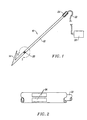
- a localization wire 10 constructed in accordance with the principles of the present invention comprises a shaft 12 and an anchor 14 in the form of a barb disposed at a distal end of the shaft 12.
- the construction of the localization wire 10 may be generally conventional, as described in the listing above of breast lesion localization and/or biopsy devices, except that it will include at least one illumination source 20 usually located near its distal end, typically within 0.5 cm of the distal end, and preferably within 0.1 cm of the distal end.
- an optical fiber 22 extends from a proximal end 24 of the shaft 12 to a plurality of windows 26 formed about the shaft 12.
- Optical wave guide 22 terminates at or near a dispersion element within the window 26 so that light transmitted down the fiber 22 will be dispersed through the windows, preferably in a generally isotropic pattern.
- Light may be directed down the optical fiber 22 from a light source 30 connected to the optical fiber 22 via a cable 32.
- An exemplary dispersion element may comprise an irregular reflective surface 27 disposed to receive coherent or other light from the optical fiber 22, as illustrated in Fig. 3 .
- Light from the optical fiber 12 strikes the reflective surface 27 and is reflected randomly and generally in a proximal direction through the windows 26.
- other dispersion elements could be employed, including lenses, e.g., spherical lenses, refractive surfaces, refractive gratings, and the like.
- Localization wire 30 may be generally the same as localization wire 10, including a shaft 32 and an anchor 14, but will further include a plurality of windows 36 spaced apart axially along its length.
- An optical fiber or wavelength 33 runs axially through the shaft 32 and includes a plurality of optical dispersion elements or points along its length generally aligned with each of the windows 36.
- optical waveguide 33 may comprise a plurality of individual fibers, where a number of the exterior fibers terminate adjacent to each of the windows 36, leaving inner wires to extend down the shaft to the additional windows 36 located distally. This is observed in Fig. 5 where a pair of optical fibers 33a and 33b are shown as terminating adjacent the window 36. Usually, a number of additional individual fibers will also be terminated in order to provide sufficient illumination in each window.
- the localization wires of the present invention may have a wide variety of other forms.
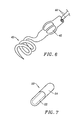
- the anchors may be in the form of a helix or spiral 40, as shown in Fig. 6 .
- the light source may take forms other than single or multiple fiber optical wave guides.
- a light-emitting diode 42 is disposed within an open or transparent region of the shaft of the localization wire. The light-emitting diode may be connected to an external power source via wires 44.
- the methods of the present invention may employ light-emitting implantable capsules, such as capsule 50 illustrated in Fig. 7 .
- Capsule 50 may comprise any low power illumination source, such as a light-emitting diode 52 together with a battery typically located in adjacent compartment 54.
- the capsule 50 will be capable of emitting illumination, preferably infrared illumination, after it is implanted within solid tissue, as described in more detail hereinafter.
- the light-emitting implantable capsule may be configured to permit remote activation, e.g., an ultrasonic, infrared, or other signal detector may be included within the capsule to permit the capsule to be turned on (and in some instances off) after the capsule has been implanted in tissue.
- the illumination source will have a limited lifetime dependent upon the power available from the battery. Thus, permitting the ability to externally actuate the life can significantly reduce the size of battery required and thus the physical size of the capsule itself. Inclusion of the remote activation switch will be particularly useful when the device is planted as part of a biopsy procedure, as described hereinafter.
- the localization wire 10 will typically be introduced through a needle or cannula 60 which may be positioned fluoroscopically so that its distal tip 62 lies adjacent to the lesion L. In some instances, the localization wire 10 will be positioned following stereotactic biopsy so that the distal tip 62 lays adjacent to the site from where the tissue was removed. After the needle or cannula 60 is properly positioned, the anchor portion 14 of the wire 10 will be advanced out through the distal tip 62 so that it deploys and anchors within the tissue, as shown in Fig. 8B .
- the barb of anchor 14 may be resilient so that it may be radially collapsed as it is advanced through the needle or cannula 60 and then outwardly deploy after it is released from the distal tip 62.
- the anchor By drawing back slightly on the localization wire 10, the anchor then becomes firmly positioned within the tissue so that it is resistant to accidental movement.
- the external light source 30 can be connected via cable 32 and illumination from the illumination source 20 initiated. The surgeon may then rely on visual or optical detection of the illumination in order to guide a surgical procedure toward the illumination source and the adjacent lesion 30.
- the implantable capsule 50 may be introduced to a target site adjacent lesion L in an analogous manner.
- the needle or cannula 60 is positioned via fluoroscopic imaging and the capsule 50 is axially advanced until it emerges from the distal tip and is implanted in tissue adjacent to the lesion, as illustrated in Fig. 8B .
- the capsule 50 will then emit infrared or other illumination and act as a beacon to guide a subsequent surgical procedure in the manner described above.
- the methods and devices of the present invention may also find use following stereotactic or other tissue biopsy.
- a void V or other space will remain within the tissue T following biopsy.
- the capsule 50 may then be introduced through the cannula 60, as illustrated in Fig. 10B .
- the capsule 50 may be identical to that described previously, but will preferably include a remote actuation feature which will permit the surgeon to initiate illumination at some time following the initial implantation, typically hours, days, or even weeks later.
- the ability to precisely locate the prior site of tissue removal is of great benefit to performing subsequent excision or other procedures.
- Tissue biopsy will often at least partly remove the initial lesion which is present on the images taken prior to the biopsy procedure. Thus, relocating the site of biopsy can be problematic.
- the ability to place the marker of the present invention precisely at the site of biopsy is thus of great benefit.
- Kits according to the present invention will comprise a localization wire 10 having a distal anchor 14 and illumination source 20, as generally described in connection with Fig. 1 and 2 .
- the kit 100 will further comprise instructions for use 102 setting forth any of the methods described above. Both the localization wire 10 and instructions for use 102 will usually be packaged together in a conventional package 104, shown as a pouch. The package could also be in the form of a tube, tray, box, or the like. Other system components may also be included in the kit if desired.
- kits comprising the implantable capsule 50 could also be put together with instructions for use and optionally packaging in an analogous manner.
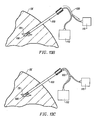
- a localization probe 100 useful for localizing and marking a radioisotopically labeled tissue site such as a radioisotopically labeled lymph node, includes a shaft 102 and apertures or opening 104 near a distal end 106 thereof.
- the distal end 106 is sharpened to facilitate percutaneous introduction to a target tissue site.
- the probe 100 will include both an illumination source and a scintillation detector or counter so that the probe may first be positioned near the radioisotopically labeled site prior to initiation of illumination.
- the scintillation detector may comprise an optical fiber having a distal end coated with a scintillation material which produces visible or otherwise detectable light when struck by radioactive particles of the type emitted by the radioisotope.
- the light fiber is then connected to a light detector 110 which will have some indication of proximity of the distal end 106 of the probe to a radioisotopic source.
- a visual signal such as a gauge
- an audible signal may be provided to the treating physician so that the physician can tell when the probe tip is getting closer to or further from the radioisotopically labeled tissue, such as the sentinel node in a breast cancer patient.
- the sentinel node SN will be radioisotopically labeled by injecting or otherwise introducing the radioisotope to the region of a primary tumor or lesion.
- the radioisotope will drain to the sentinel node, and an approximate location for the node may be determined using an external scintillation counter, i.e., scanning the scintillation counter over the patient's skin SK. Once the approximate location is determined, the probe 100 of the present invention may be percutaneously introduced through the skin SK until the distal end 106 is positioned within or adjacent to the sentinel node.
- Positioning will be based on light transmission through the optical fiber to the detector 110, as illustrated by arrow 120 in Fig. 13B .
- light from a light source 112 may then be directed to the same or a different light fiber in the direction of arrow 122.
- the light transmitted to the region of the sentinel node acts as a visual beacon as previously described.
- a probe without an integral scintillation detector (such as probe 10) may be positioned at a labeled sentinel node by first generally locating the labeled node (usually using a surface scintillation scanner) and then ultrasonically imaging the region identified by the surface scanner. The probe may then be positioned very closely to the sentinel node to provide the desired infrared or other visible signal.
Claims (8)
- Vorrichtung zum Lokalisieren einer Zielstelle in festem Gewebe, die mit einem Radioisotop markiert worden ist, die Vorrichtung umfasst:eine Leitung (10) mit einem proximalen Ende (24), einem distalen Ende und einer Verankerung (14) nahe dem distalen Ende;eine Beleuchtungsquelle (20) an der Leitung (10); undeinen Szintillationsdetektor.
- Vorrichtung nach Anspruch 1, wobei die Beleuchtungsquelle (20) eine Punktquelle ist.
- Vorrichtung nach Anspruch 1, wobei die Beleuchtungsquelle (20) eine optische Faser (22) umfasst, die axial an oder innerhalb der Leitung (10) angeordnet ist, die optische Faser (22) ist angepasst, um Licht von einer externen Quelle (30) zu übertragen und um das übertragene Licht in einem allgemeinen isotropen Muster von einem Punkt auf der Leitung (10) auszusenden.
- Vorrichtung nach Anspruch 2, wobei die Beleuchtungsquelle (20) ein Licht erzeugendes Element umfasst.
- Vorrichtung nach Anspruch 4, wobei das Licht erzeugende Element eine Licht aussendende Diode (42) ist.
- Vorrichtung nach einem der Ansprüche 1 bis 5, wobei der Szintillationsdetektor eine optische Faser mit einem distalen Ende umfasst, das mit einem Szintillationsmaterial beschichtet ist, das sichtbares oder anderweitig nachweisbares Licht erzeugt, wenn es von radioaktiven Teilchen getroffen wird, die von dem Radioisotop ausgesandt werden.
- Vorrichtung nach Anspruch 3, wobei die optische Faser (22), die angepasst ist, um Licht von einer externen Quelle (30) zu übertragen, ein distales Ende aufweist, das mit einem Szintillationsmaterial beschichtet ist, das sichtbares oder anderweitig nachweisbares Licht erzeugt, wenn es von radioaktiven Teilchen getroffen wird, die von dem Radioisotop ausgesandt werden.
- Vorrichtung nach einem der Ansprüche 1 bis 7 zur Verwendung in einer Therapie.
Applications Claiming Priority (3)
| Application Number | Priority Date | Filing Date | Title |
|---|---|---|---|
| US8096398P | 1998-04-07 | 1998-04-07 | |
| US80963P | 1998-04-07 | ||
| PCT/US1999/007589 WO1999051143A1 (en) | 1998-04-07 | 1999-04-06 | Methods and devices for the localization of lesions in solid tissue |
Publications (3)
| Publication Number | Publication Date |
|---|---|
| EP1091685A1 EP1091685A1 (de) | 2001-04-18 |
| EP1091685A4 EP1091685A4 (de) | 2002-02-13 |
| EP1091685B1 true EP1091685B1 (de) | 2008-06-11 |
Family
ID=22160797
Family Applications (1)
| Application Number | Title | Priority Date | Filing Date |
|---|---|---|---|
| EP99917356A Expired - Lifetime EP1091685B1 (de) | 1998-04-07 | 1999-04-06 | Vorrichtungen zur lokalisierung von läsionen in festem gewebe |
Country Status (6)
| Country | Link |
|---|---|
| US (1) | US6336904B1 (de) |
| EP (1) | EP1091685B1 (de) |
| AT (1) | ATE397887T1 (de) |
| AU (1) | AU3550099A (de) |
| DE (1) | DE69938898D1 (de) |
| WO (1) | WO1999051143A1 (de) |
Families Citing this family (106)
| Publication number | Priority date | Publication date | Assignee | Title |
|---|---|---|---|---|
| US8668737B2 (en) | 1997-10-10 | 2014-03-11 | Senorx, Inc. | Tissue marking implant |
| US7637948B2 (en) | 1997-10-10 | 2009-12-29 | Senorx, Inc. | Tissue marking implant |
| US6161034A (en) * | 1999-02-02 | 2000-12-12 | Senorx, Inc. | Methods and chemical preparations for time-limited marking of biopsy sites |
| US6347241B2 (en) * | 1999-02-02 | 2002-02-12 | Senorx, Inc. | Ultrasonic and x-ray detectable biopsy site marker and apparatus for applying it |
| US7983734B2 (en) | 2003-05-23 | 2011-07-19 | Senorx, Inc. | Fibrous marker and intracorporeal delivery thereof |
| US6862470B2 (en) | 1999-02-02 | 2005-03-01 | Senorx, Inc. | Cavity-filling biopsy site markers |
| US8361082B2 (en) | 1999-02-02 | 2013-01-29 | Senorx, Inc. | Marker delivery device with releasable plug |
| US7651505B2 (en) | 2002-06-17 | 2010-01-26 | Senorx, Inc. | Plugged tip delivery for marker placement |
| US6725083B1 (en) | 1999-02-02 | 2004-04-20 | Senorx, Inc. | Tissue site markers for in VIVO imaging |
| US8498693B2 (en) | 1999-02-02 | 2013-07-30 | Senorx, Inc. | Intracorporeal marker and marker delivery device |
| US9820824B2 (en) | 1999-02-02 | 2017-11-21 | Senorx, Inc. | Deployment of polysaccharide markers for treating a site within a patent |
| US20080039819A1 (en) * | 2006-08-04 | 2008-02-14 | Senorx, Inc. | Marker formed of starch or other suitable polysaccharide |
| US20090030309A1 (en) * | 2007-07-26 | 2009-01-29 | Senorx, Inc. | Deployment of polysaccharide markers |
| US7174201B2 (en) * | 1999-03-11 | 2007-02-06 | Biosense, Inc. | Position sensing system with integral location pad and position display |
| US7590441B2 (en) * | 1999-03-11 | 2009-09-15 | Biosense, Inc. | Invasive medical device with position sensing and display |
| US6575991B1 (en) | 1999-06-17 | 2003-06-10 | Inrad, Inc. | Apparatus for the percutaneous marking of a lesion |
| US6611700B1 (en) * | 1999-12-30 | 2003-08-26 | Brainlab Ag | Method and apparatus for positioning a body for radiation using a position sensor |
| US6564806B1 (en) * | 2000-02-18 | 2003-05-20 | Thomas J. Fogarty | Device for accurately marking tissue |
| WO2001060235A2 (en) * | 2000-02-18 | 2001-08-23 | Fogarty Thomas J M D | Improved device for accurately marking tissue |
| US20040006274A1 (en) * | 2000-10-16 | 2004-01-08 | Cole Giller | Method and apparatus for probe localization in brain matter |
| EP1919388B1 (de) | 2000-11-20 | 2012-12-26 | Senorx, Inc. | Gewebestellemarker für in vivo bilddarstellungen |
| US9492111B2 (en) * | 2002-04-22 | 2016-11-15 | Medtronic Minimed, Inc. | Methods and materials for stabilizing analyte sensors |
| US6786628B2 (en) * | 2002-07-03 | 2004-09-07 | Advanced Medical Optics | Light source for ophthalmic use |
| US20040077951A1 (en) * | 2002-07-05 | 2004-04-22 | Wei-Chiang Lin | Apparatus and methods of detection of radiation injury using optical spectroscopy |
| US20060036158A1 (en) | 2003-11-17 | 2006-02-16 | Inrad, Inc. | Self-contained, self-piercing, side-expelling marking apparatus |
| DE60330705D1 (de) | 2002-11-18 | 2010-02-04 | Bard Peripheral Vascular Inc | Gerät zum implantieren eines vorgespannten lokalisierungsdrahtes |
| US20040111133A1 (en) * | 2002-12-10 | 2004-06-10 | Alcon, Inc. | LED illuminator |
| US7877133B2 (en) | 2003-05-23 | 2011-01-25 | Senorx, Inc. | Marker or filler forming fluid |
| US20050119562A1 (en) * | 2003-05-23 | 2005-06-02 | Senorx, Inc. | Fibrous marker formed of synthetic polymer strands |
| WO2005032342A2 (en) * | 2003-09-30 | 2005-04-14 | Vanderbilt University | Methods and apparatus for optical spectroscopic detection of cell and tissue death |
| US20050273002A1 (en) | 2004-06-04 | 2005-12-08 | Goosen Ryan L | Multi-mode imaging marker |
| US20050190982A1 (en) * | 2003-11-28 | 2005-09-01 | Matsushita Electric Industrial Co., Ltd. | Image reducing device and image reducing method |
| JP4578817B2 (ja) * | 2004-02-06 | 2010-11-10 | オリンパス株式会社 | 外科手術用病変部同定システム |
| US20050234336A1 (en) * | 2004-03-26 | 2005-10-20 | Beckman Andrew T | Apparatus and method for marking tissue |
| US20090216115A1 (en) * | 2004-07-23 | 2009-08-27 | Calypso Medical Technologies, Inc. | Anchoring wirless markers within a human body |
| US8419656B2 (en) | 2004-11-22 | 2013-04-16 | Bard Peripheral Vascular, Inc. | Post decompression marker introducer system |
| US8409111B2 (en) | 2004-11-22 | 2013-04-02 | Bard Peripheral Vascular, Inc. | Removable localizing wire |
| US10357328B2 (en) | 2005-04-20 | 2019-07-23 | Bard Peripheral Vascular, Inc. and Bard Shannon Limited | Marking device with retractable cannula |
| DE102005032373A1 (de) * | 2005-07-08 | 2006-12-07 | Siemens Ag | Medizinisches System |
| US9238150B2 (en) | 2005-07-22 | 2016-01-19 | The Board Of Trustees Of The Leland Stanford Junior University | Optical tissue interface method and apparatus for stimulating cells |
| US20090093403A1 (en) | 2007-03-01 | 2009-04-09 | Feng Zhang | Systems, methods and compositions for optical stimulation of target cells |
| US9274099B2 (en) * | 2005-07-22 | 2016-03-01 | The Board Of Trustees Of The Leland Stanford Junior University | Screening test drugs to identify their effects on cell membrane voltage-gated ion channel |
| US10052497B2 (en) * | 2005-07-22 | 2018-08-21 | The Board Of Trustees Of The Leland Stanford Junior University | System for optical stimulation of target cells |
| US8926959B2 (en) * | 2005-07-22 | 2015-01-06 | The Board Of Trustees Of The Leland Stanford Junior University | System for optical stimulation of target cells |
| JP2009502140A (ja) * | 2005-07-22 | 2009-01-29 | ザ ボード オブ トラスティーズ オブ ザ レランド スタンフォード ジュニア ユニバーシティー | 光活性化陽イオンチャネルおよびその使用 |
| CA2562580C (en) | 2005-10-07 | 2014-04-29 | Inrad, Inc. | Drug-eluting tissue marker |
| US20090216113A1 (en) | 2005-11-17 | 2009-08-27 | Eric Meier | Apparatus and Methods for Using an Electromagnetic Transponder in Orthopedic Procedures |
| US20080230001A1 (en) * | 2006-02-23 | 2008-09-25 | Meadwestvaco Corporation | Method for treating a substrate |
| US8064987B2 (en) | 2006-10-23 | 2011-11-22 | C. R. Bard, Inc. | Breast marker |
| US9579077B2 (en) | 2006-12-12 | 2017-02-28 | C.R. Bard, Inc. | Multiple imaging mode tissue marker |
| ES2432572T3 (es) | 2006-12-18 | 2013-12-04 | C.R. Bard, Inc. | Marcador de biopsia con propiedades de obtención de imágenes generadas in situ |
| WO2008086470A1 (en) | 2007-01-10 | 2008-07-17 | The Board Of Trustees Of The Leland Stanford Junior University | System for optical stimulation of target cells |
| US8401609B2 (en) | 2007-02-14 | 2013-03-19 | The Board Of Trustees Of The Leland Stanford Junior University | System, method and applications involving identification of biological circuits such as neurological characteristics |
| WO2009050667A1 (en) * | 2007-10-18 | 2009-04-23 | Koninklijke Philips Electronics N.V. | Tumor demarcation using targeted fluorescent probe and photonic needle |
| US10035027B2 (en) * | 2007-10-31 | 2018-07-31 | The Board Of Trustees Of The Leland Stanford Junior University | Device and method for ultrasonic neuromodulation via stereotactic frame based technique |
| US10434327B2 (en) | 2007-10-31 | 2019-10-08 | The Board Of Trustees Of The Leland Stanford Junior University | Implantable optical stimulators |
| WO2009099767A2 (en) | 2008-01-31 | 2009-08-13 | C.R. Bard, Inc. | Biopsy tissue marker |
| CN102088896B (zh) * | 2008-03-18 | 2013-11-20 | 皇家飞利浦电子股份有限公司 | 活组织检查装置 |
| ES2608498T3 (es) | 2008-04-23 | 2017-04-11 | The Board Of Trustees Of The Leland Stanford Junior University | Sistemas, métodos y composiciones para la estimulación óptica de células diana |
| JP2009273610A (ja) * | 2008-05-14 | 2009-11-26 | Toshihiko Sato | 留置機能を備えたicタグ |
| AU2009256457B2 (en) | 2008-05-29 | 2014-06-26 | The Board Of Trustees Of The Leland Stanford Junior University | Cell line, system and method for optical control of secondary messengers |
| EP3192562B1 (de) * | 2008-06-17 | 2020-03-04 | The Board of Trustees of the Leland Stanford Junior University | Vorrichtungen zur optischen stimulierung von zielzellen mit einem optischen transmissionselement |
| CA2728402A1 (en) * | 2008-06-17 | 2009-12-23 | The Board Of Trustees Of The Leland Stanford Junior University | Apparatus and methods for controlling cellular development |
| WO2010006049A1 (en) | 2008-07-08 | 2010-01-14 | The Board Of Trustees Of The Leland Stanford Junior University | Materials and approaches for optical stimulation of the peripheral nervous system |
| US20100025238A1 (en) * | 2008-07-31 | 2010-02-04 | Medtronic Minimed, Inc. | Analyte sensor apparatuses having improved electrode configurations and methods for making and using them |
| US8700114B2 (en) * | 2008-07-31 | 2014-04-15 | Medtronic Minmed, Inc. | Analyte sensor apparatuses comprising multiple implantable sensor elements and methods for making and using them |
| US9327061B2 (en) | 2008-09-23 | 2016-05-03 | Senorx, Inc. | Porous bioabsorbable implant |
| NZ602416A (en) | 2008-11-14 | 2014-08-29 | Univ Leland Stanford Junior | Optically-based stimulation of target cells and modifications thereto |
| WO2010077244A1 (en) | 2008-12-30 | 2010-07-08 | C.R. Bard Inc. | Marker delivery device for tissue marker placement |
| US9943704B1 (en) | 2009-01-21 | 2018-04-17 | Varian Medical Systems, Inc. | Method and system for fiducials contained in removable device for radiation therapy |
| US20120109151A1 (en) * | 2009-04-03 | 2012-05-03 | Ruprecht-Karls-Universität Heidelberg | System and Computer Assisted Surgery |
| CA2779965A1 (en) * | 2009-12-17 | 2011-06-23 | Alcon Research, Ltd. | Photonic lattice leds for ophthalmic illumination |
| US20110148304A1 (en) * | 2009-12-22 | 2011-06-23 | Artsyukhovich Alexander N | Thermoelectric cooling for increased brightness in a white light l.e.d. illuminator |
| WO2011078958A1 (en) * | 2009-12-23 | 2011-06-30 | Alcon Research, Ltd. | Enhanced led illuminator |
| SG183899A1 (en) | 2010-03-17 | 2012-10-30 | Univ Leland Stanford Junior | Light-sensitive ion-passing molecules |
| US9314374B2 (en) * | 2010-03-19 | 2016-04-19 | Alcon Research, Ltd. | Stroboscopic ophthalmic illuminator |
| US8573801B2 (en) | 2010-08-30 | 2013-11-05 | Alcon Research, Ltd. | LED illuminator |
| BR112013009961A2 (pt) * | 2010-10-27 | 2019-09-24 | Koninl Philips Electronics Nv | agulha, sistema e método. |
| WO2012061690A2 (en) | 2010-11-05 | 2012-05-10 | The Board Of Trustees Of The Leland Stanford Junior University | Optically-controlled cns dysfunction |
| CA2816990A1 (en) | 2010-11-05 | 2012-05-10 | The Board Of Trustees Of The Leland Stanford Junior University | Stabilized step function opsin proteins and methods of using the same |
| JP6355335B2 (ja) | 2010-11-05 | 2018-07-11 | ザ ボード オブ トラスティーズ オブ ザ レランド スタンフォード ジュニア ユニバーシティー | 報酬関連行動の光遺伝学的制御 |
| CN110215614A (zh) | 2010-11-05 | 2019-09-10 | 斯坦福大学托管董事会 | 用于光遗传学方法的光的上转换 |
| CA2816971A1 (en) | 2010-11-05 | 2012-05-10 | The Board Of Trustees Of The Leland Stanford Junior University | Light-activated chimeric opsins and methods of using the same |
| WO2012061681A1 (en) | 2010-11-05 | 2012-05-10 | The Board Of Trustees Of The Leland Stanford Junior University. | Control and characterization of memory function |
| US8696722B2 (en) | 2010-11-22 | 2014-04-15 | The Board Of Trustees Of The Leland Stanford Junior University | Optogenetic magnetic resonance imaging |
| EP3524676A1 (de) | 2011-12-16 | 2019-08-14 | The Board of Trustees of The Leland Stanford Junior University | Opsin-polypeptide und verfahren zu ihrer verwendung |
| JP6537826B2 (ja) | 2012-02-21 | 2019-07-03 | ザ ボード オブ トラスティーズ オブ ザ レランド スタンフォード ジュニア ユニバーシティー | 骨盤底の神経性障害を処置するための組成物および方法 |
| EP2968997B1 (de) | 2013-03-15 | 2019-06-26 | The Board of Trustees of the Leland Stanford Junior University | Optogenetische steuerung des verhaltenszustandes |
| US9636380B2 (en) | 2013-03-15 | 2017-05-02 | The Board Of Trustees Of The Leland Stanford Junior University | Optogenetic control of inputs to the ventral tegmental area |
| AU2014260101B2 (en) | 2013-04-29 | 2018-07-26 | Humboldt-Universitat Zu Berlin | Devices, systems and methods for optogenetic modulation of action potentials in target cells |
| AU2014306679A1 (en) | 2013-08-14 | 2016-03-10 | Circuit Therapeutics, Inc. | Compositions and methods for controlling pain |
| EP3033033B1 (de) | 2013-08-15 | 2019-10-23 | Intuitive Surgical Operations, Inc. | Systeme und verfahren zur bestätigung eines medizinischen verfahrens |
| USD715942S1 (en) | 2013-09-24 | 2014-10-21 | C. R. Bard, Inc. | Tissue marker for intracorporeal site identification |
| USD716451S1 (en) | 2013-09-24 | 2014-10-28 | C. R. Bard, Inc. | Tissue marker for intracorporeal site identification |
| USD715442S1 (en) | 2013-09-24 | 2014-10-14 | C. R. Bard, Inc. | Tissue marker for intracorporeal site identification |
| USD716450S1 (en) | 2013-09-24 | 2014-10-28 | C. R. Bard, Inc. | Tissue marker for intracorporeal site identification |
| EP3232921B1 (de) * | 2014-12-16 | 2019-09-25 | Koninklijke Philips N.V. | Pulslichtemittierende markierungsvorrichtung |
| WO2016209654A1 (en) | 2015-06-22 | 2016-12-29 | The Board Of Trustees Of The Leland Stanford Junior University | Methods and devices for imaging and/or optogenetic control of light-responsive neurons |
| US9913804B2 (en) * | 2015-12-31 | 2018-03-13 | Incube Labs, Llc | Solid drug storage apparatus, formulations and methods of use |
| US10070938B2 (en) | 2016-05-20 | 2018-09-11 | David LeBeau | Stabilization device and method for surgical localization wire |
| US11172560B2 (en) | 2016-08-25 | 2021-11-09 | Alcon Inc. | Ophthalmic illumination system with controlled chromaticity |
| US11294165B2 (en) | 2017-03-30 | 2022-04-05 | The Board Of Trustees Of The Leland Stanford Junior University | Modular, electro-optical device for increasing the imaging field of view using time-sequential capture |
| EP3685785A1 (de) * | 2019-01-22 | 2020-07-29 | Stryker European Holdings I, LLC | Verfolger für ein chirurgisches navigationssystem |
| WO2021162838A1 (en) * | 2020-02-12 | 2021-08-19 | Covidien Lp | Devices and systems for marking tissue |
| KR102655108B1 (ko) * | 2021-05-24 | 2024-04-08 | 서울대학교병원 | 통증 시술용 척추 니들, 니들 커빙기 및 이를 포함하는 통증 시술 키트 |
| CN116250940A (zh) * | 2021-12-10 | 2023-06-13 | 广州迪克医疗器械有限公司 | 用于医用光学示踪的光纤机构及医用光学示踪系统 |
Family Cites Families (25)
| Publication number | Priority date | Publication date | Assignee | Title |
|---|---|---|---|---|
| US4248214A (en) | 1979-05-22 | 1981-02-03 | Robert S. Kish | Illuminated urethral catheter |
| US4541438A (en) | 1983-06-02 | 1985-09-17 | The Johns Hopkins University | Localization of cancerous tissue by monitoring infrared fluorescence emitted by intravenously injected porphyrin tumor-specific markers excited by long wavelength light |
| US4592356A (en) | 1984-09-28 | 1986-06-03 | Pedro Gutierrez | Localizing device |
| US4817622A (en) | 1986-07-22 | 1989-04-04 | Carl Pennypacker | Infrared imager for viewing subcutaneous location of vascular structures and method of use |
| US4774948A (en) | 1986-11-24 | 1988-10-04 | Markham Charles W | Marking and retraction needle having retrievable stylet |
| US4813422A (en) | 1987-03-06 | 1989-03-21 | Healthcare Technological Resources, Inc. | Bowel control probe and method for controlling bowel incontinence |
| US5555885A (en) | 1988-12-21 | 1996-09-17 | Non-Invasive Technology, Inc. | Examination of breast tissue using time-resolved spectroscopy |
| US4966583A (en) | 1989-02-03 | 1990-10-30 | Elie Debbas | Apparatus for locating a breast mass |
| US5197482A (en) | 1989-06-15 | 1993-03-30 | Research Corporation Technologies, Inc. | Helical-tipped lesion localization needle device and method of using the same |
| US5158084A (en) | 1989-11-22 | 1992-10-27 | Board Of Regents, The University Of Texas System | Modified localization wire for excisional biopsy |
| US5014713A (en) | 1989-12-05 | 1991-05-14 | Tarris Enterprises, Inc. | Method and apparatus for measuring thickness of fat using infrared light |
| US5353804A (en) | 1990-09-18 | 1994-10-11 | Peb Biopsy Corporation | Method and device for percutaneous exisional breast biopsy |
| US5221269A (en) | 1990-10-15 | 1993-06-22 | Cook Incorporated | Guide for localizing a nonpalpable breast lesion |
| US5423321A (en) | 1993-02-11 | 1995-06-13 | Fontenot; Mark G. | Detection of anatomic passages using infrared emitting catheter |
| US5409004A (en) | 1993-06-11 | 1995-04-25 | Cook Incorporated | Localization device with radiopaque markings |
| US5556410A (en) | 1993-09-27 | 1996-09-17 | M3 Systems, Inc. | Surgical needle with stress-relocation means |
| US5394887A (en) * | 1994-01-14 | 1995-03-07 | Haaga; John R. | Biopsy needle |
| US5650135A (en) * | 1994-07-01 | 1997-07-22 | The Board Of Trustees Of The Leland Stanford Junior University | Non-invasive localization of a light-emitting conjugate in a mammal |
| US5517997A (en) | 1994-09-15 | 1996-05-21 | Gabriel Medical, Inc. | Transillumination of body members for protection during body invasive procedures |
| US5660185A (en) | 1995-04-13 | 1997-08-26 | Neovision Corporation | Image-guided biopsy apparatus with enhanced imaging and methods |
| US5782771A (en) | 1995-04-17 | 1998-07-21 | Hussman; Karl L. | Dual, fused, and grooved optical localization fibers |
| JP3609487B2 (ja) | 1995-05-16 | 2005-01-12 | Ntn株式会社 | 針状ころ軸受用保持器 |
| US5792215A (en) | 1995-09-18 | 1998-08-11 | The University Of Virginia Patent Foundation | Laser integrated targeting and entry system and method |
| US5902310A (en) * | 1996-08-12 | 1999-05-11 | Ethicon Endo-Surgery, Inc. | Apparatus and method for marking tissue |
| US6056700A (en) * | 1998-10-13 | 2000-05-02 | Emx, Inc. | Biopsy marker assembly and method of use |
-
1999
- 1999-04-06 WO PCT/US1999/007589 patent/WO1999051143A1/en active Application Filing
- 1999-04-06 AT AT99917356T patent/ATE397887T1/de not_active IP Right Cessation
- 1999-04-06 EP EP99917356A patent/EP1091685B1/de not_active Expired - Lifetime
- 1999-04-06 US US09/287,087 patent/US6336904B1/en not_active Expired - Lifetime
- 1999-04-06 DE DE69938898T patent/DE69938898D1/de not_active Expired - Lifetime
- 1999-04-06 AU AU35500/99A patent/AU3550099A/en not_active Abandoned
Also Published As
| Publication number | Publication date |
|---|---|
| AU3550099A (en) | 1999-10-25 |
| EP1091685A4 (de) | 2002-02-13 |
| US6336904B1 (en) | 2002-01-08 |
| EP1091685A1 (de) | 2001-04-18 |
| ATE397887T1 (de) | 2008-07-15 |
| WO1999051143A1 (en) | 1999-10-14 |
| DE69938898D1 (de) | 2008-07-24 |
Similar Documents
| Publication | Publication Date | Title |
|---|---|---|
| EP1091685B1 (de) | Vorrichtungen zur lokalisierung von läsionen in festem gewebe | |
| US6716179B2 (en) | Sentinel node location and biopsy | |
| US6484050B1 (en) | Minimally invasive surgical instrument for tissue identification, dislodgment and retrieval and methods of use | |
| JP4294220B2 (ja) | 組織を一括して除去するためのシステムおよび方法 | |
| US7282034B2 (en) | Tissue accessing and anchoring device and method | |
| US6175760B1 (en) | Lesion localizer for nuclear medicine | |
| JP3939360B2 (ja) | エネルギー案内器具および案内方法 | |
| ES2323966T3 (es) | Aparato para marcar tejidos. | |
| EP2249737B1 (de) | Biopsie-führung mithilfe elektromagnetischer verfolgung und einer photonischen nadel | |
| US6654629B2 (en) | Implantable biomarker and method of use | |
| CN103648416B (zh) | 用于基准点部署的系统 | |
| US7074189B1 (en) | Endoscopically deliverable ultrasound imaging system and method of use | |
| US20080021449A1 (en) | Electrosurgical lesion location device | |
| US20080281190A1 (en) | Surgical procedures | |
| WO2000024332A1 (en) | Marker for indicating the location of identified tissue | |
| WO1999025248A1 (en) | Minimally invasive surgical probe for tissue identification and retrieval and method of use | |
| JPH10508504A (ja) | 組織を特定しおよびマーキングする方法および装置 | |
| WO2007117478A2 (en) | Marking and scanning surical targets in vivo | |
| WO2009050667A1 (en) | Tumor demarcation using targeted fluorescent probe and photonic needle | |
| JP2010000284A (ja) | Icタグを用いた手術方法 | |
| US11737679B2 (en) | Localization systems and methods of use | |
| KR20210098264A (ko) | 시인성 마커 |
Legal Events
| Date | Code | Title | Description |
|---|---|---|---|
| PUAI | Public reference made under article 153(3) epc to a published international application that has entered the european phase |
Free format text: ORIGINAL CODE: 0009012 |
|
| 17P | Request for examination filed |
Effective date: 20010119 |
|
| AK | Designated contracting states |
Kind code of ref document: A1 Designated state(s): AT BE CH CY DE DK ES FI FR GB GR IE IT LI LU MC NL PT SE |
|
| A4 | Supplementary search report drawn up and despatched |
Effective date: 20020103 |
|
| AK | Designated contracting states |
Kind code of ref document: A4 Designated state(s): AT BE CH CY DE DK ES FI FR GB GR IE IT LI LU MC NL PT SE |
|
| RIC1 | Information provided on ipc code assigned before grant |
Free format text: 7A 61B 5/00 A, 7A 61B 19/00 B |
|
| RAP1 | Party data changed (applicant data changed or rights of an application transferred) |
Owner name: CYTYC HEALTH CORPORATION |
|
| 17Q | First examination report despatched |
Effective date: 20041126 |
|
| RAP1 | Party data changed (applicant data changed or rights of an application transferred) |
Owner name: CYTYC CORPORATION |
|
| GRAP | Despatch of communication of intention to grant a patent |
Free format text: ORIGINAL CODE: EPIDOSNIGR1 |
|
| RTI1 | Title (correction) |
Free format text: DEVICES FOR THE LOCALIZATION OF LESIONS IN SOLID TISSUE |
|
| GRAS | Grant fee paid |
Free format text: ORIGINAL CODE: EPIDOSNIGR3 |
|
| GRAA | (expected) grant |
Free format text: ORIGINAL CODE: 0009210 |
|
| AK | Designated contracting states |
Kind code of ref document: B1 Designated state(s): AT BE CH CY DE DK ES FI FR GB GR IE IT LI LU MC NL PT SE |
|
| REG | Reference to a national code |
Ref country code: GB Ref legal event code: FG4D |
|
| REG | Reference to a national code |
Ref country code: CH Ref legal event code: EP |
|
| REF | Corresponds to: |
Ref document number: 69938898 Country of ref document: DE Date of ref document: 20080724 Kind code of ref document: P |
|
| REG | Reference to a national code |
Ref country code: IE Ref legal event code: FG4D |
|
| PG25 | Lapsed in a contracting state [announced via postgrant information from national office to epo] |
Ref country code: FI Free format text: LAPSE BECAUSE OF FAILURE TO SUBMIT A TRANSLATION OF THE DESCRIPTION OR TO PAY THE FEE WITHIN THE PRESCRIBED TIME-LIMIT Effective date: 20080611 |
|
| PG25 | Lapsed in a contracting state [announced via postgrant information from national office to epo] |
Ref country code: NL Free format text: LAPSE BECAUSE OF FAILURE TO SUBMIT A TRANSLATION OF THE DESCRIPTION OR TO PAY THE FEE WITHIN THE PRESCRIBED TIME-LIMIT Effective date: 20080611 Ref country code: AT Free format text: LAPSE BECAUSE OF FAILURE TO SUBMIT A TRANSLATION OF THE DESCRIPTION OR TO PAY THE FEE WITHIN THE PRESCRIBED TIME-LIMIT Effective date: 20080611 |
|
| NLV1 | Nl: lapsed or annulled due to failure to fulfill the requirements of art. 29p and 29m of the patents act | ||
| PG25 | Lapsed in a contracting state [announced via postgrant information from national office to epo] |
Ref country code: SE Free format text: LAPSE BECAUSE OF FAILURE TO SUBMIT A TRANSLATION OF THE DESCRIPTION OR TO PAY THE FEE WITHIN THE PRESCRIBED TIME-LIMIT Effective date: 20080911 Ref country code: PT Free format text: LAPSE BECAUSE OF FAILURE TO SUBMIT A TRANSLATION OF THE DESCRIPTION OR TO PAY THE FEE WITHIN THE PRESCRIBED TIME-LIMIT Effective date: 20081111 Ref country code: ES Free format text: LAPSE BECAUSE OF FAILURE TO SUBMIT A TRANSLATION OF THE DESCRIPTION OR TO PAY THE FEE WITHIN THE PRESCRIBED TIME-LIMIT Effective date: 20080922 |
|
| PG25 | Lapsed in a contracting state [announced via postgrant information from national office to epo] |
Ref country code: BE Free format text: LAPSE BECAUSE OF FAILURE TO SUBMIT A TRANSLATION OF THE DESCRIPTION OR TO PAY THE FEE WITHIN THE PRESCRIBED TIME-LIMIT Effective date: 20080611 |
|
| PLBE | No opposition filed within time limit |
Free format text: ORIGINAL CODE: 0009261 |
|
| STAA | Information on the status of an ep patent application or granted ep patent |
Free format text: STATUS: NO OPPOSITION FILED WITHIN TIME LIMIT |
|
| PG25 | Lapsed in a contracting state [announced via postgrant information from national office to epo] |
Ref country code: DK Free format text: LAPSE BECAUSE OF FAILURE TO SUBMIT A TRANSLATION OF THE DESCRIPTION OR TO PAY THE FEE WITHIN THE PRESCRIBED TIME-LIMIT Effective date: 20080611 |
|
| 26N | No opposition filed |
Effective date: 20090312 |
|
| PG25 | Lapsed in a contracting state [announced via postgrant information from national office to epo] |
Ref country code: IT Free format text: LAPSE BECAUSE OF FAILURE TO SUBMIT A TRANSLATION OF THE DESCRIPTION OR TO PAY THE FEE WITHIN THE PRESCRIBED TIME-LIMIT Effective date: 20080611 |
|
| REG | Reference to a national code |
Ref country code: CH Ref legal event code: PL |
|
| PG25 | Lapsed in a contracting state [announced via postgrant information from national office to epo] |
Ref country code: LI Free format text: LAPSE BECAUSE OF NON-PAYMENT OF DUE FEES Effective date: 20090430 Ref country code: CH Free format text: LAPSE BECAUSE OF NON-PAYMENT OF DUE FEES Effective date: 20090430 |
|
| PG25 | Lapsed in a contracting state [announced via postgrant information from national office to epo] |
Ref country code: MC Free format text: LAPSE BECAUSE OF NON-PAYMENT OF DUE FEES Effective date: 20090430 |
|
| PG25 | Lapsed in a contracting state [announced via postgrant information from national office to epo] |
Ref country code: GR Free format text: LAPSE BECAUSE OF FAILURE TO SUBMIT A TRANSLATION OF THE DESCRIPTION OR TO PAY THE FEE WITHIN THE PRESCRIBED TIME-LIMIT Effective date: 20080912 |
|
| PG25 | Lapsed in a contracting state [announced via postgrant information from national office to epo] |
Ref country code: LU Free format text: LAPSE BECAUSE OF NON-PAYMENT OF DUE FEES Effective date: 20090406 |
|
| PG25 | Lapsed in a contracting state [announced via postgrant information from national office to epo] |
Ref country code: CY Free format text: LAPSE BECAUSE OF FAILURE TO SUBMIT A TRANSLATION OF THE DESCRIPTION OR TO PAY THE FEE WITHIN THE PRESCRIBED TIME-LIMIT Effective date: 20080611 |
|
| REG | Reference to a national code |
Ref country code: FR Ref legal event code: PLFP Year of fee payment: 17 |
|
| PGFP | Annual fee paid to national office [announced via postgrant information from national office to epo] |
Ref country code: DE Payment date: 20150331 Year of fee payment: 17 Ref country code: GB Payment date: 20150401 Year of fee payment: 17 |
|
| PGFP | Annual fee paid to national office [announced via postgrant information from national office to epo] |
Ref country code: IE Payment date: 20150409 Year of fee payment: 17 Ref country code: FR Payment date: 20150408 Year of fee payment: 17 |
|
| REG | Reference to a national code |
Ref country code: DE Ref legal event code: R119 Ref document number: 69938898 Country of ref document: DE |
|
| GBPC | Gb: european patent ceased through non-payment of renewal fee |
Effective date: 20160406 |
|
| REG | Reference to a national code |
Ref country code: IE Ref legal event code: MM4A |
|
| REG | Reference to a national code |
Ref country code: FR Ref legal event code: ST Effective date: 20161230 |
|
| PG25 | Lapsed in a contracting state [announced via postgrant information from national office to epo] |
Ref country code: DE Free format text: LAPSE BECAUSE OF NON-PAYMENT OF DUE FEES Effective date: 20161101 Ref country code: GB Free format text: LAPSE BECAUSE OF NON-PAYMENT OF DUE FEES Effective date: 20160406 Ref country code: FR Free format text: LAPSE BECAUSE OF NON-PAYMENT OF DUE FEES Effective date: 20160502 |
|
| PG25 | Lapsed in a contracting state [announced via postgrant information from national office to epo] |
Ref country code: IE Free format text: LAPSE BECAUSE OF NON-PAYMENT OF DUE FEES Effective date: 20160406 |