EP1091160A2 - Formteil - Google Patents
Formteil Download PDFInfo
- Publication number
- EP1091160A2 EP1091160A2 EP00121711A EP00121711A EP1091160A2 EP 1091160 A2 EP1091160 A2 EP 1091160A2 EP 00121711 A EP00121711 A EP 00121711A EP 00121711 A EP00121711 A EP 00121711A EP 1091160 A2 EP1091160 A2 EP 1091160A2
- Authority
- EP
- European Patent Office
- Prior art keywords
- molding according
- molded part
- passage
- molding
- branch
- Prior art date
- Legal status (The legal status is an assumption and is not a legal conclusion. Google has not performed a legal analysis and makes no representation as to the accuracy of the status listed.)
- Withdrawn
Links
- 238000010101 extrusion blow moulding Methods 0.000 claims abstract description 3
- 238000007789 sealing Methods 0.000 claims description 33
- 238000000465 moulding Methods 0.000 claims description 21
- 238000003466 welding Methods 0.000 claims description 5
- 239000000853 adhesive Substances 0.000 claims description 4
- 230000001070 adhesive effect Effects 0.000 claims description 4
- 238000004519 manufacturing process Methods 0.000 claims description 4
- 238000000034 method Methods 0.000 claims description 4
- 230000008569 process Effects 0.000 claims description 4
- 230000007704 transition Effects 0.000 claims description 3
- 238000010309 melting process Methods 0.000 claims description 2
- 238000007499 fusion processing Methods 0.000 abstract 1
- 238000009412 basement excavation Methods 0.000 description 2
- 230000009471 action Effects 0.000 description 1
- 230000004913 activation Effects 0.000 description 1
- 230000008901 benefit Effects 0.000 description 1
- 230000008602 contraction Effects 0.000 description 1
- 230000003247 decreasing effect Effects 0.000 description 1
- 238000009826 distribution Methods 0.000 description 1
- 238000001125 extrusion Methods 0.000 description 1
- 238000001746 injection moulding Methods 0.000 description 1
- 238000009413 insulation Methods 0.000 description 1
- 230000000149 penetrating effect Effects 0.000 description 1
- 239000000126 substance Substances 0.000 description 1
Images


Classifications
-
- F—MECHANICAL ENGINEERING; LIGHTING; HEATING; WEAPONS; BLASTING
- F16—ENGINEERING ELEMENTS AND UNITS; GENERAL MEASURES FOR PRODUCING AND MAINTAINING EFFECTIVE FUNCTIONING OF MACHINES OR INSTALLATIONS; THERMAL INSULATION IN GENERAL
- F16L—PIPES; JOINTS OR FITTINGS FOR PIPES; SUPPORTS FOR PIPES, CABLES OR PROTECTIVE TUBING; MEANS FOR THERMAL INSULATION IN GENERAL
- F16L59/00—Thermal insulation in general
- F16L59/14—Arrangements for the insulation of pipes or pipe systems
- F16L59/16—Arrangements specially adapted to local requirements at flanges, junctions, valves or the like
- F16L59/163—Branch units; Insulation forming a whole with branches
Definitions
- the invention relates to a molded part for covering joints thermally insulated Pipes, consisting of a passage element and one of these pioneering Branch element, wherein the molded part on at least one outer side of the passage element and / or the branching element pointing away from this one Has opening extending over the entire length of the outside.
- connection points for heat-insulated pipes for example in the case of T-shaped or L-shaped branches
- these connection points must be subsequently insulated and covered.
- half-shells are used in the known prior art, which are produced from extruded tubes in such a way that after welding two tubes together to form a T-shaped molded part, the latter is cut completely over its outer sides and is thus used as a cover part. After the insulation, these half-shells are placed on the connection points of heat-insulated pipes, sealed against one another and against the heat-insulated pipes and then fixed by means of separate fastening elements such as screws, tensioning straps and the like.
- a further disadvantage of such molded parts is that they have a constant diameter over their entire length. This can mean that when covering connection points of heat-insulated pipes with different diameters, these are not exactly positioned and fixed by the molded part. There is a gap between the molded part and the branching heat-insulated pipe with a reduced diameter, which is only covered by a shrink tube, which cannot withstand the mechanical and chemical stresses of a connection point of heat-insulated pipes in the long run.
- Such molded parts can also be used only at connection points of heat-insulated pipes, where a corresponding branch must be created for a continuous pipe. Such molded parts cannot be used to cover L-shaped connection points of heat-insulated pipes.
- connection point is also disadvantageous forming spiral shape of the molded part.
- Another object of the invention is to provide a molded part which can be used for both T-shaped and L-shaped connection points of heat-insulated pipes and which can be sealed quickly and safely after assembly.
- the object is achieved in that the surfaces resulting from the introduction of the opening are approximately parallel to one another, in that the branching element points away from the passage element at a defined angle and in that the lumen of the molded part can be covered by a closure element at at least one free end.
- the object is further achieved in that the passage element is surrounded by a sealing element, the sealing elements being designed on at least one free end such that they overlap at least in partial areas.
- connection points of heat-insulated pipes can thus be covered easily and without problems, since the surfaces created by the introduction of the opening do not abut one another spirally.
- the lumen can be covered at least at one free end by a closure element, which on the one hand fixes the opening made in the molded part and on the other hand the molded part can be used in a multifunctional manner.
- Another advantage of the molded part according to the invention is that at least one free end of the molded part is molded onto at least one ring section with a reduced diameter lying in the axial direction. Furthermore, it is within the scope of the invention to make the ring section conical, concave or convex.
- the molded part according to the invention can be used for the connection points of heat-insulated pipes with different diameters.
- the ring section corresponding to the diameter of the heat-insulated pipes has to be separated from the molded part at the connection point to be assembled.
- the center of the ring section with the reduced outer diameter is arranged concentrically to the central part of the molded part. This makes it possible to center the molded part on the connection point of the heat-insulated pipes and to fix them accordingly.
- the center point of the ring section with the reduced diameter is eccentric to the axis of the molded part. This makes it possible for a concentric arrangement to cover connection points of heat-insulated pipes laid in the ground, and the distribution of the loads on the molded part and the connection point to be optimized accordingly.
- the invention further teaches that the branch element of the molded part at an angle of 10 ° points away from the passage element up to 90 ° to the central axis of the molded part.
- the molded part according to the invention both for T-shaped joints can also be used for Y-shaped or L-shaped connection points.
- the opening that is necessary around the molded part to cover the junction of thermally insulated Using pipes can be introduced at various points marked on the molded part so that assembly is always optimized in terms of time and costs can be carried out.
- the molded part according to the invention can advantageously be produced by means of the rotary melting process and also in the extrusion blow molding process. This is particularly advantageous since, after the manufacturing process, the molded part has almost no residual stresses, so that an opening to be made subsequently does not lead to a spiral contraction of the molded part.
- the molded part can consist of two mutually opposite passage elements, at the common interface of which the branch element points away from it at a certain angle.
- the invention further teaches that the surface of the molded part by alternating Wave crests and wave valleys can be formed.
- This corrugated structure makes it possible to give the molded part greater flexibility to lend.
- the molded part can also advantageously be more thermally insulated for covering connection points Pipes are used where there is a shut-off element between the pipes is attached, which at a later time, for example, after closing the excavation pit must still be operable from the outside.
- the fast and secure sealing of the connection point of heat-insulated pipes by means of the molded part according to the invention can be achieved by using sealing elements each with overlapping, obliquely designed free ends, the overlapping free ends of which are arranged opposite the branching element.
- This can advantageously achieve that the opening of the molded part is doubly secured in the critical area and that the oblique design of the free ends of the sealing element means that they can be positioned very quickly and safely around the passage element.
- the sealing element can its free ends have a concave and / or a convex shape.
- you can corresponding to the requirements of the molded part on its sealing Select the design of the free end of the sealing element, which is also an S-shaped Shape has proven to be very advantageous.
- the one facing the passage element Inner surface of the sealing element coated with an adhesive so that a circumferential Sealing of the passage element and / or the branch element can be realized.
- a further advantageous sealing of the molded part according to the invention can be achieved by means of welding processes, in particular extruder or hot air welding. It is possible not only to close the opening opposite the branch element, but also the transitions from the molded part according to the invention to the heat-insulated pipes. In order to achieve increased durability of this connection, the transitions from the molded part to the heat-insulated pipes can additionally be secured with the sealing elements described above, in which case the beveling of the free ends of the sealing elements or their overlap can also be dispensed with.
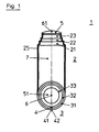
- the molded part 1 is shown in a view from the.
- the one pointing upwards Branch element 2 has at its free end 25 the ring sections 21, 22, 23, which have decreasing diameters.
- the closure element 5 can be seen, which in this embodiment is integral with the free end 25 of the branch element 2 of the molded part 1 is connected.
- the closure element 5 thus closes the lumen 7 of the branch element 2 of the molded part 1.
- the opening 4 extends over the entire length of the outside and runs through the ring sections 31, 32, 33, which in axial direction have a step-like reduced outer diameter up to Closure element 51.
- the center 6 of the ring sections 31, 32, 33 as well as the center 61 of the ring sections 21, 22, 23 are designed concentrically to the central part of the molding.
- the molded part 1 shown in FIG. 2 consists of two opposite passage elements 3, 3 'and a branch element 2 pointing away at their intersection. At the free ends 35, 35' of the passage elements 3, 3 'are the ring sections 31, 31' , 32, 32 'formed in one piece, which have a reduced diameter lying in the axial direction.
- the ring section 32, 32 'of the passage element 3, 3' is integrally formed by a closure element 51, 51 ', the closure element 51, 51' closing the lumen 7 of the passage element 3, 3 'of the molded part 1.
- a branch element 2 pointing away from the latter at an angle of approximately 90 ° is formed in one piece.
- ring sections 21, 22, 23 with a reduced diameter are also formed in the axial direction.
- the free end 25 with the ring sections 21, 22, 23 is covered by the closure element 5, which thus closes the lumen 7 of the branch element 2 of the molded part 1.
- the opening 4 was made in the outside of the passage elements 3, 3 ', from which the branch element 2 points at approximately a right angle, and in the outer sides of the branch element 2.
- the molded part 1 connects two heat-insulated pipes 300, 310.
- the tubes 70, 71 protrude from the heat-insulated tubes 300, 310 and are parallel run to the central part of the molded part of the passage elements 3, 3 'and that via a shut-off element 8 are interconnected.
- the ring sections 31, 31 ', 32, 32' formed on the free ends 35, 35 'of the passage elements 3, 3' in the axial direction are no longer closed, so that the outermost ring section 32, 32 'has an inner diameter which corresponds to the outer diameter of the heat-insulated pipes 300, 310.
- the opening 4 is introduced on the outside of the passage elements 3, 3 ′ opposite the branch element 2
- both the closure element 5 and the ring sections lying in the axial direction have been removed, so that a channel element 9, which can be closed by a cover 10, can be fastened via the free end 25 of the branch element 2.
- the shut-off element 8 is available at all times via the branch element 2, the channel element 9, without the need for complex excavation work.
- the molded part 1 has two passage elements 3, 3 ′ lying opposite one another and a branch element 2 pointing away at their intersection.
Landscapes
- Engineering & Computer Science (AREA)
- General Engineering & Computer Science (AREA)
- Mechanical Engineering (AREA)
- Thermal Insulation (AREA)
- Extrusion Moulding Of Plastics Or The Like (AREA)
Abstract
Description
Hierzu werden im bekannten Stand der Technik Halbschalen verwendet, welche aus extrudierten Rohren derart hergestellt werden, dass nach dem Verschweißen von zwei Rohren zu einem T-förmigen Formteil dieses komplett über seine Außenseiten aufgeschnitten und so als Abdeckteil verwendet wird. Diese Halbschalen werden nach der Isolierung auf die Verbindungsstellen wärmeisolierter Rohre aufgesetzt, gegeneinander und gegen die wärmeisolierten Rohre abgedichtet und dann durch separate Befestigungselemente wie Schrauben, Spannbänder und ähnliches fixiert. Diese Halbschalen, die auch im Spritzgießverfahren herstellbar sind, sind sehr zeit- und personalaufwendig auf den Verbindungsstellen wärmeisolierter Rohre zu montieren, wobei Montagefehler beispielsweise durch die Verwendung unterschiedlicher Halbschalen oder nicht spezifikationsgerechter Positionierung nicht ausgeschlossen sind. Ein weiterer Nachteil dieser Halbschalen besteht in ihrem aufwendigen Herstellungsverfahren, was neben den hohen Montageaufwendungen keine wirtschaftliche Verwertung zulässt.
Die Montage solcher Formteile gestaltet sich derart, dass diese über die Verbindungsstelle der abzweigenden wärmeisolierten Rohre geschoben werden und nach dem Abdichten der Verbindungsstelle durch Auseinanderziehen der an der dem Abzweig gegenüberliegenden Längsseite angebrachten Öffnung über die Verbindungsstelle der abzweigenden wärmeisolierten Rohre gezogen werden müssen, um diese abzudecken.
Derartige Formteile können auch nur bei Verbindungsstellen wärmeisolierter Rohre eingesetzt werden, wo für ein durchgehendes Rohr ein entsprechender Abzweig geschaffen werden muss. Nicht einsetzbar sind derartige Formteile zum Abdecken von L-förmigen Verbindungsstellen wärmeisolierter Rohre.
Eine weitere Aufgabe der Erfindung besteht darin, ein Formteil zur Verfügung zu stellen, weiches sowohl bel T-förmigen als auch bel L-förmigen Verbindungsstellen wärmeisolierter Rohre verwendbar ist und das nach der Montage schnell und sicher abdichtbar ist.
Die Aufgabe wird weiterhin dadurch gelöst, dass das Durchgangselement von einem Abdichtungselement umgeben ist, wobei die Abdichtelemente an mindestens einem freien Enden so ausgeführt sind, dass diese sich wenigstens in Teilbereichen überlappend überdecken.
Ein weiterer Vorteil des erfindungsgemäßen Formteils besteht darin, dass an wenigstens einem freien Ende des Formteils wenigstens an in axialer Richtung liegender Ringabschnitt mit reduziertem Durchmesser angeformt ist. Weiterhin liegt es im Rahmen der Erfindung, den Ringabschnitt kegelförmig, konkav oder konvex auszuführen.
Das erfindungsgemäße Formteil kann in dieser Ausführungsform für die Verbindungsstellen von wärmeisolierten Rohren mit unterschiedlichen Durchmessern verwendet werden.
Dazu muss an der zu montierenden Verbindungsstelle nur jeweils der dem Durchmesser der wärmeisolierten Rohre entsprechende Ringabschnitt vom Formteil abgetrennt werden.
In einer vorteilhaften Ausführungsform ist der Mittelpunkt des Ringabschnittes mit dem reduzierten Durchmesser exzentrisch zur Formteilmittelachse. Dadurch ist es möglich, dass zum Abdecken von Verbindungsstellen von im Erdreich verlegten wärmeisolierten Rohren eine konzentrische Anordnung erfolgt und somit die Verteilung der Belastungen auf das Formteil und die Verbindungsstelle entsprechend optimiert werden kann.
In einer weiteren Ausführungsform, beispielsweise bei einer Verbindungsstelle von drei winklig zueinanderführenden wärmeisolierten Rohren kann das Formteil aus zwei sich gegenüberliegenden Durchgangselementen bestehen, an deren gemeinsamer Schnittstelle das Abzweigelement in einem bestimmten Winkel davon wegweist.
Hierdurch kann vorteilhaft erreicht werden, dass die Öffnung des Formteils im kritischen Bereich doppelt abgesichert ist und dass durch die schräge Ausführung der freien Enden des Abdichtelementes diese sehr schnell und sicher um das Durchgangselement positionierbar sind.
Um erhöhte Dauerhaftigkeit dieser Verbindung zu erreichen, können die Übergänge vom Formteil auf die wärmeisolierten Rohre zusätzlich mit den vorbeschriebenen Abdichtelementen gesichert werden, wobei in diesem Fall auch auf die Abschrägung der freien Enden der Abdichtelemente oder auf deren Überlappung verzichtet werden kann.
- Figur 1
- Schnittdarstellung durch ein erfindungsgemäßes Formteil
- Figur 2
- Schnittdarstellung durch eine Ausführungsform des erfindungsgemäßen Formteiles
- Figur 3
- Montageprinzip des erfindungsgemäßen Formteils
- Figur 4:
- Schnittdarstellung durch eine Ausführungsform eines abgedichteten erfindungsgemäßen Formteiles
Das in Figur 2 dargestellte Formteil 1 besteht in dieser Ausführungsform aus zwei sich gegenüberliegenden Durchgangselementen 3, 3' und einem in deren Schnittpunkt wegweisenden Abzweigelement 2. An den freien Enden 35, 35' der Durchgangselemente 3, 3' sind die Ringabschnitte 31, 31', 32, 32' einstückig angeformt, welche einen in axiale Richtung liegenden reduzierten Durchmesser aufweisen. Am Ringabschnitt 32, 32' des Durchgangselementes 3, 3' ist durch ein Verschlusselement 51, 51' einstückig angeformt, wobei das Verschlusselement 51, 51' das Lumen 7 des Durchgangselementes 3, 3' des Formteiles 1 verschließt. An der Schnittstelle der Durchgangselemente 3, 3' ist ein von diesem im Winkel von annähernd 90° wegweisendes Abzweigelement 2 einstückig angeformt. Am freien Ende 25 des Abzweigelementes 2 des Formteiles 1 sind ebenfalls in axialer Richtung liegende Ringabschnitte 21, 22, 23 mit reduziertem Durchmesser angeformt. Das freie Ende 25 mit den Ringabschnitten 21, 22, 23 wird durch das Verschlusselement 5 abgedeckt, welches somit das Lumen 7 des Abzweigelementes 2 des Formteiles 1 verschließt. In der hier dargestellten Ausführungsform wurde die Öffnung 4 in der Außenseite der Durchgangselemente 3, 3', von der annähernd rechtwinklig das Abzweigelement 2 wegweist, sowie in die Außenseiten des Abzweigelementes 2 eingebracht. In der auf der linken Seite gezeigten Halbschnittdarstellung ist erkennbar, dass die durch die Öffnung 4 entstandene Fläche 41 vom Ringabschnitt 32 des Durchgangselementes 3 und des Durchgangselementes 3' verlaufend beginnt und am Ringabschnitt 23 des Abzweigelementes 2 des Formteiles 1 endet. In dieser Ausführungsform kann eine L-förmige Verbindungsstelle wärmeisolierter Rohre abgedeckt werden.
Am freien Ende 25 des Abzweigelementes 2 wurde sowohl das Verschlusselement 5 als auch die in axialer Richtung liegenden Ringabschnitte entfernt, so dass über das freie Ende 25 des Abzweigelementes 2 ein Kanalelement 9 befestigbar ist, welches durch einen Deckel 10 verschließbar ist. In dieser Ausführungsform ist das Absperrelement 8 jederzeit über das Abzweigelement 2, das Kanalelement 9 verfügbar, ohne dass aufwendige Aufgrabungsarbeiten erforderlich sind.
In dieser Ausführungsform sind die Abdichtelemente 60, 60' Schrumpfschläuche, welche an der Innenfläche mit einem Klebstoff beschichtet sind. Die Abdichtelemente 60, 60' werden so auf dem Durchgangselement 3, 3' angeordnet, dass sich die freien Enden 61, 61' wenigstens teilweise überdecken und dass die spitzen Enden 62, 62' gegenüber dem Abzweigelement 2 angeordnet sind. Durch Temperatureinwirkung auf die Abdichtelemente 60, 60' und die damit verbundene Aktivierung des auf der Innenseite der Abdichtelemente 60, 60' befindlichen Klebstoffes erfolgt nun die endgültige Abdichtung des erfindungsgemäßen Formteiles 1.
Claims (20)
- Formteil zum Abdecken von Verbindungsstellen wärmeisolierter Rohre, bestehend aus einem Durchgangselement und einem von diesem wegweisenden Abzweigelement, wobei das Formteil an wenigstens einer Außenseite des Durchgangselementes und/oder des von diesem wegweisenden Abzweigelementes eine sich über die gesamte Länge der Außenseite erstreckende Öffnung aufweist,
dadurch gekennzeichnet,
dass die durch das Einbringen der Öffnung (4) entstehenden Flächen (41, 42) annähernd parallel einander gegenüberstehen, dass das Abzweigelement (2) in einem definierten Winkel vom Durchgangselement (3, 3') wegweist und dass das Lumen (7) des Formteiles (1) an wenigstens einem freien Ende (25, 35, 36) durch ein Verschlusselement (5, 51, 51') abgedeckt sein kann. - Formteil nach Anspruch 1, dadurch gekennzeichnet, dass an wenigstens einem freien Ende (25, 35, 35') des Formteiles (1) wenigstens ein in axialer Richtung liegender Ringabschnitt (21, 22, 23, 31, 32, 33) mit reduziertem Durchmesser angeformt ist.
- Formteil nach einem der vorhergehenden Ansprüche, dadurch gekennzeichnet, dass der Mittelpunkt (6) des in axialer Richtung liegenden Ringabschnittes (21, 22, 23, 31, 32, 33) mit reduziertem Durchmesser konzentrisch zur Formteilmittelachse ist.
- Formteil nach einem der vorhergehenden Ansprüche, dadurch gekennzeichnet, dass der Mittelpunkt (6) des in axialer Richtung liegenden Ringabschnittes (21, 22, 23, 31, 32, 33) mit reduziertem Durchmesser exzentrisch zur Formteilmittelachse ist.
- Formteil nach einem der vorhergehenden Ansprüche, dadurch gekennzeichnet, dass die Oberfläche durch alternierende Wellenberge und Wellentäler ausgebildet ist.
- Formteil nach einem der vorhergehenden Ansprüche, dadurch gekennzeichnet, dass das Abzweigelement (2) in einem Winkel von 10° bis 90° zur Formteilmittelachse und Durchgangselement wegweist.
- Formteil nach einem der vorhergehenden Ansprüche, dadurch gekennzeichnet dass die Herstellung durch Rotationsschmelzverfahren oder Extrusionsblasverfahren erfolgt.
- Formteil nach einem der vorhergehenden Ansprüche, dadurch gekennzeichnet, dass es nach dem Herstellungsprozess annähernd keine Eigenspannungen aufweist.
- Formteil zum Abdecken von Verbindungsstellen wärmeisolierter Rohre, bestehend aus einem Durchgangselement und einem von diesem weg weisenden Abzweigelement, wobei das Formteil an wenigstens einer Außenseite des Durchgangselementes und/oder des von diesem weg weisenden Abzweigelementes eine sich über die gesamte Länge der Außenseite erstreckende Öffnung aufweist,
dadurch gekennzeichnet,
dass das Durchgangselement (3, 3') von einem Abdichtelement (60, 60') umgeben ist, wobei das Abdichtelement (60, 60') an mindestens einem freien Ende (61, 61') so ausgeführt ist, dass diese freien Enden (61, 61') sich wenigstens in Teilbereichen überlappend überdecken. - Formteil nach Anspruch 9, dadurch gekennzeichnet, dass die sich überlappenden freien Enden (61, 61') des Abdichtelements (60, 60') dem Abzweigelement (2) gegenüber angeordnet sind.
- Formteil nach den Ansprüchen 9 bis 10, dadurch gekennzeichnet, dass die freien Enden (61, 61') des Abdichtelementes (60, 60') schräg ausgeführt sind.
- Formteil nach den Ansprüchen 9 bis 11, dadurch gekennzeichnet, dass die freien Enden (61, 61') des Abdichtelementes (60, 60') konkav ausgeführt sind.
- Formteil nach den Ansprüchen 9 bis 12, dadurch gekennzeichnet dass die freien Enden (61, 61') des Abdichtelementes (60, 60') konvex ausgeführt sind.
- Formteil nach den Ansprüchen 9 bis 13, dadurch gekennzeichnet dass die freien Enden (61, 61') des Abdichtelementes (60, 60') S-förmig ausgeführt sind.
- Formteil nach den Ansprüchen 9 bis 14, dadurch gekennzeichnet dass das Abdichtelement (60, 60') schlauchförmig ist.
- Formteil nach den Ansprüchen 9 bis 15, dadurch gekennzeichnet, dass das Abdichtelement (60, 60') ein Schrumpfschlauch ist.
- Formteil nach den Ansprüchen 9 bis 16, dadurch gekennzeichnet, dass die dem Durchgangselement (3, 3') zugewandte Innenfläche des Abdichtelementes (60, 60') mit einem Klebstoff beschichtet ist.
- Formteil nach einem der vorhergehenden Ansprüche, dadurch gekennzeichnet, dass die dem Abzweigelement (2) gegenüberliegende Öffnung (4) des Durchgangselementes (3,3') mittels Schweißverfahren geschlossen wird.
- Formteil nach einem der vorhergehenden Ansprüche, dadurch gekennzeichnet dass Übergänge vom Formteil auf die wärmeisolierten Rohre mittels Schweißverfahren geschlossen werden.
- Formteil nach Anspruch 18 oder 19, dadurch gekennzeichnet dass bei den Abdichtelementen (60,60') auf die Abschrägung der freien Enden (61,61') oder auf die Überlappung der Abdichtelemente verzichtet wird.
Applications Claiming Priority (2)
| Application Number | Priority Date | Filing Date | Title |
|---|---|---|---|
| DE29917508U | 1999-10-05 | ||
| DE29917508U DE29917508U1 (de) | 1999-10-05 | 1999-10-05 | Formteil |
Publications (2)
| Publication Number | Publication Date |
|---|---|
| EP1091160A2 true EP1091160A2 (de) | 2001-04-11 |
| EP1091160A3 EP1091160A3 (de) | 2003-06-25 |
Family
ID=8079852
Family Applications (1)
| Application Number | Title | Priority Date | Filing Date |
|---|---|---|---|
| EP00121711A Withdrawn EP1091160A3 (de) | 1999-10-05 | 2000-10-04 | Formteil |
Country Status (2)
| Country | Link |
|---|---|
| EP (1) | EP1091160A3 (de) |
| DE (1) | DE29917508U1 (de) |
Families Citing this family (1)
| Publication number | Priority date | Publication date | Assignee | Title |
|---|---|---|---|---|
| DE20204399U1 (de) * | 2002-03-19 | 2003-04-30 | REHAU AG + Co., 95111 Rehau | Rohrabzweig |
Family Cites Families (10)
| Publication number | Priority date | Publication date | Assignee | Title |
|---|---|---|---|---|
| DE7436866U (de) | 1975-02-20 | Klein K | Gehäuse für wärmeisolierte Rohrleitungsschieber | |
| US3191632A (en) * | 1962-01-29 | 1965-06-29 | Keiding Paper Products Company | Pipe jacket |
| US4353859A (en) * | 1973-08-01 | 1982-10-12 | Sherwin Palmer | Method for making fittings and couplings |
| DE7903573U1 (de) | 1979-02-09 | 1979-05-03 | Kabel- Und Metallwerke Gutehoffnungshuette Ag, 3000 Hannover | Kunststoffisolierkoerper zum nachisolieren von rohren |
| DE8033089U1 (de) | 1980-12-12 | 1981-03-12 | Kabel- und Metallwerke Gutehoffnungshütte AG, 3000 Hannover | Kunststoffisolierkoerper zum nachisolieren von rohren |
| NL8100776A (nl) * | 1981-02-17 | 1982-09-16 | Wavin Bv | Isolatiebuisdeel, alsmede geisoleerde aftakbuisverbinding. |
| DE8321417U1 (de) | 1983-07-26 | 1983-11-10 | Karl Klein Kunststoffabrik, 7970 Leutkirch | Gehaeuse fuer waermeisolierte rohrleitungsschieber |
| US5524669A (en) | 1990-08-20 | 1996-06-11 | Truebro, Inc. | Thermal insulation for angle-valve piping |
| DE9314094U1 (de) * | 1993-09-17 | 1993-11-25 | KM-kabelmetal AG, 49074 Osnabrück | Formkörper aus Kunststoff für Verbindungs- und Abzweigstellen wärmeisolierter Metallrohre |
| DE29616774U1 (de) | 1996-09-26 | 1996-11-14 | BRUGG Rohrsysteme GmbH, 31515 Wunstorf | Anordnung zur T-förmigen Abzweigung eines Leitungsrohres |
-
1999
- 1999-10-05 DE DE29917508U patent/DE29917508U1/de not_active Expired - Lifetime
-
2000
- 2000-10-04 EP EP00121711A patent/EP1091160A3/de not_active Withdrawn
Non-Patent Citations (1)
| Title |
|---|
| None |
Also Published As
| Publication number | Publication date |
|---|---|
| DE29917508U1 (de) | 1999-12-30 |
| EP1091160A3 (de) | 2003-06-25 |
Similar Documents
| Publication | Publication Date | Title |
|---|---|---|
| DE2820181A1 (de) | Verschluss fuer ein laengsgeschlitztes kabelmuffenrohr | |
| EP0848200B1 (de) | Rohrpresskupplung | |
| DE20211150U1 (de) | Schlauch, insbesondere Sanitärschlauch | |
| DE3047867A1 (de) | Rohrverbindung | |
| DE102011110219B4 (de) | Verfahren zum Herstellen eines Wickelschlauches, insbesondere Agraffschlauch sowie Wickelschlauch und flexibles Leitungselement mit einem Wickelschlauch | |
| DE4103278A1 (de) | Bauelement zur waermedaemmung bei gebaeuden | |
| DE19536703A1 (de) | Rohr, insbesondere Kunststoffrohr, und Rohrverbindung aus solchen Rohren | |
| EP2020576A2 (de) | Solarkollektor zum Erwärmen einer Flüssigkeit | |
| DE102019002736A1 (de) | Verwendung einer Manschette zum Verbinden von Leitungen, Verfahren zum Verbinden von Leitungen eines Wärmetauschermoduls und Wärmetauschersystem mit der entsprechenden Verbindung | |
| DE29917508U1 (de) | Formteil | |
| EP0583596B1 (de) | Sickerleitungsrohr | |
| EP1956149A1 (de) | Schlauch, inbesondere Brauseschlauch, mit Umspritzung | |
| EP0160890A2 (de) | Auf einem Stützgerüst befestigbarer Abgaskanal | |
| DE3112101C2 (de) | Einrichtung für den Zusammenschluß von Wellrohrenden einer trommelbaren Koaxial-Wellrohr-Fernheizleitung | |
| EP1128112A1 (de) | Fixpunktbride für eine Rohrleitung | |
| DE202014003776U1 (de) | Kunststoffrohr | |
| DE102008058355B4 (de) | Solarkollektor zum Erwärmen einer Flüssigkeit | |
| DE2827416A1 (de) | Rohrleitung aus waermeisolierten rohren | |
| DE202021106545U1 (de) | Tülle mit Gelenkverbindung | |
| DE69100542T2 (de) | Muffenrohr aus Kunststoff sowie Herstellungsverfahren dafür. | |
| DE102008007226A1 (de) | Verbundrohr mit schraubenförmiger Wellung und dessen Verwendung als Abwasserrohr oder Erdkollektor | |
| DE19734689C2 (de) | Anordnung zur Verbindung einer rohr- oder schlauchförmigen Leitung aus Kunststoff mit einem Stahlrohrabschnitt | |
| EP0060513A1 (de) | Brauseschlauch | |
| DE2849380A1 (de) | Rohrmuffe | |
| EP0709611B1 (de) | Einführungsvorrichtung für eine Gasleitung in ein Gebäude |
Legal Events
| Date | Code | Title | Description |
|---|---|---|---|
| PUAI | Public reference made under article 153(3) epc to a published international application that has entered the european phase |
Free format text: ORIGINAL CODE: 0009012 |
|
| AK | Designated contracting states |
Kind code of ref document: A2 Designated state(s): AT BE CH CY DE DK ES FI FR GB GR IE IT LI LU MC NL PT SE |
|
| AX | Request for extension of the european patent |
Free format text: AL;LT;LV;MK;RO;SI |
|
| PUAL | Search report despatched |
Free format text: ORIGINAL CODE: 0009013 |
|
| AK | Designated contracting states |
Designated state(s): AT BE CH CY DE DK ES FI FR GB GR IE IT LI LU MC NL PT SE |
|
| AX | Request for extension of the european patent |
Extension state: AL LT LV MK RO SI |
|
| 17P | Request for examination filed |
Effective date: 20030728 |
|
| AKX | Designation fees paid |
Designated state(s): AT BE CH CY DE DK ES FI FR GB GR IE IT LI LU MC NL PT SE |
|
| 17Q | First examination report despatched |
Effective date: 20040428 |
|
| STAA | Information on the status of an ep patent application or granted ep patent |
Free format text: STATUS: THE APPLICATION IS DEEMED TO BE WITHDRAWN |
|
| 18D | Application deemed to be withdrawn |
Effective date: 20050913 |