EP1091049A2 - Hydraulic excavator - Google Patents
Hydraulic excavator Download PDFInfo
- Publication number
- EP1091049A2 EP1091049A2 EP00121772A EP00121772A EP1091049A2 EP 1091049 A2 EP1091049 A2 EP 1091049A2 EP 00121772 A EP00121772 A EP 00121772A EP 00121772 A EP00121772 A EP 00121772A EP 1091049 A2 EP1091049 A2 EP 1091049A2
- Authority
- EP
- European Patent Office
- Prior art keywords
- boom
- roof supports
- cabin
- roof
- work attachment
- Prior art date
- Legal status (The legal status is an assumption and is not a legal conclusion. Google has not performed a legal analysis and makes no representation as to the accuracy of the status listed.)
- Granted
Links
Images
Classifications
-
- E—FIXED CONSTRUCTIONS
- E02—HYDRAULIC ENGINEERING; FOUNDATIONS; SOIL SHIFTING
- E02F—DREDGING; SOIL-SHIFTING
- E02F9/00—Component parts of dredgers or soil-shifting machines, not restricted to one of the kinds covered by groups E02F3/00 - E02F7/00
- E02F9/16—Cabins, platforms, or the like, for drivers
-
- E—FIXED CONSTRUCTIONS
- E02—HYDRAULIC ENGINEERING; FOUNDATIONS; SOIL SHIFTING
- E02F—DREDGING; SOIL-SHIFTING
- E02F9/00—Component parts of dredgers or soil-shifting machines, not restricted to one of the kinds covered by groups E02F3/00 - E02F7/00
- E02F9/16—Cabins, platforms, or the like, for drivers
- E02F9/163—Structures to protect drivers, e.g. cabins, doors for cabins; Falling object protection structure [FOPS]; Roll over protection structure [ROPS]
-
- E—FIXED CONSTRUCTIONS
- E02—HYDRAULIC ENGINEERING; FOUNDATIONS; SOIL SHIFTING
- E02F—DREDGING; SOIL-SHIFTING
- E02F3/00—Dredgers; Soil-shifting machines
- E02F3/04—Dredgers; Soil-shifting machines mechanically-driven
- E02F3/28—Dredgers; Soil-shifting machines mechanically-driven with digging tools mounted on a dipper- or bucket-arm, i.e. there is either one arm or a pair of arms, e.g. dippers, buckets
- E02F3/30—Dredgers; Soil-shifting machines mechanically-driven with digging tools mounted on a dipper- or bucket-arm, i.e. there is either one arm or a pair of arms, e.g. dippers, buckets with a dipper-arm pivoted on a cantilever beam, i.e. boom
- E02F3/32—Dredgers; Soil-shifting machines mechanically-driven with digging tools mounted on a dipper- or bucket-arm, i.e. there is either one arm or a pair of arms, e.g. dippers, buckets with a dipper-arm pivoted on a cantilever beam, i.e. boom working downwardly and towards the machine, e.g. with backhoes
- E02F3/325—Backhoes of the miniature type
-
- E—FIXED CONSTRUCTIONS
- E02—HYDRAULIC ENGINEERING; FOUNDATIONS; SOIL SHIFTING
- E02F—DREDGING; SOIL-SHIFTING
- E02F9/00—Component parts of dredgers or soil-shifting machines, not restricted to one of the kinds covered by groups E02F3/00 - E02F7/00
- E02F9/08—Superstructures; Supports for superstructures
-
- E—FIXED CONSTRUCTIONS
- E02—HYDRAULIC ENGINEERING; FOUNDATIONS; SOIL SHIFTING
- E02F—DREDGING; SOIL-SHIFTING
- E02F9/00—Component parts of dredgers or soil-shifting machines, not restricted to one of the kinds covered by groups E02F3/00 - E02F7/00
- E02F9/08—Superstructures; Supports for superstructures
- E02F9/10—Supports for movable superstructures mounted on travelling or walking gears or on other superstructures
-
- E—FIXED CONSTRUCTIONS
- E02—HYDRAULIC ENGINEERING; FOUNDATIONS; SOIL SHIFTING
- E02F—DREDGING; SOIL-SHIFTING
- E02F9/00—Component parts of dredgers or soil-shifting machines, not restricted to one of the kinds covered by groups E02F3/00 - E02F7/00
- E02F9/20—Drives; Control devices
- E02F9/2025—Particular purposes of control systems not otherwise provided for
- E02F9/2033—Limiting the movement of frames or implements, e.g. to avoid collision between implements and the cabin
Definitions
- the present invention relates to a compact hydraulic excavator.
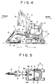
- an upper rotating body 2 is mounted on a crawler type traveling body 1 rotatably about a longitudinal axis, as shown in FIGS. 4 and 5.
- a cabin 4 is provided in a central portion of the upper surface of the upper rotating body 2.
- the cabin 4 is provided downward of a seat with an engine and other machineries (not shown) and on both left and right sides with lever type operating devices 5, 5.
- a handrail 6 is mounted forward of the cabin 4.
- a work attachment 7 is mounted directly forward of the handrail 6.
- the work attachment 7 is provided with a rising and falling boom 8.
- an arm 9 is mounted at the extreme end of the boom 8
- a bucket 10 is mounted at the extreme end of the arm 9.
- Reference numeral 11 denotes a boom rising and falling cylinder for rising and falling the boom 8.
- Numeral 12 denotes an arm cylinder for operating the arm 9.
- Numeral 13 denotes a bucket cylinder for operating the bucket 10.
- the boom 8 is mounted to be swung in a lateral direction about a longitudinal axis so that groove excavation work can be done easily.
- the boom 8 is driven by a swing cylinder 14.
- a lateral rail 6b is mounted horizontally and formed in an inverted U shape between longitudinal rails 6a, 6a on both left and right sides.
- the handrail 6 is used as a railing for supporting the body by hands when an operator leans forward to confirm the excavating part or when the operator gets on and off.
- the lateral rail 6b of the handrail 6 interferes with the boom 8 in a stood upright state of the boom 8, as shown by the phantom outline in FIG. 4. Therefore, the maximum upright angle of the boom 8 is limited to an angle smaller than an original angle of the excavator (hereinafter referred to as a specification angle). This poses a problem that the minimum rotating radius R1 of the upper construction body including the work attachment 7 increases.
- the whole height of the handrail 6 be set to be low so as not to interfere with the boom 8. However, if so, the longitudinal rails 6a, 6a particularly often used are lowered, and the function as an original railing materially lowers.
- the compact excavator of this kind is normally not provided with a roof.
- the hydraulic excavator comprises the following constitution. That is, it comprises a excavator body (a base machine) provided with a traveling body, a cabin provided on the upper surface of the excavator body, and a work attachment mounted forward of the excavator body, the work attachment comprising a boom that can be risen and fallen and can be swung on left and right about a longitudinal axis, roof supports provided forward of the cabin and on both sides at the rear of the boom, in which the boom is arranged so as not to interfere with the roof supports in a whole rising and falling range over a whole swing operating range, and so as to be projected rearward of the roof supports in a maximum stand-up state, and a roof provided above the roof supports to cover the cabin from a top of the cabin.
- the roof supports is used to be as railing too.
- the roof supports on which a roof is mounted serve as a longitudinal railing also and are arranged so as not to interfere with the boom in the whole rising and falling range over the whole swing operating range of the boom, thus taking effect as follows:
- the hydraulic excavator according to the present invention has the following constitution: a lateral railing and connecting bar provided at an arrangement not to interfere with the boom between the roof supports.
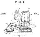
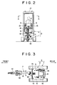
- Longitudinal railings and left and right front roof supports 15, 15, and left and right rear roof supports 16, 16 are stood upright on both left and right sides forward of a cabin 4 in an upper rotating body 2 of a excavator body 3, and on both left and right sides rearward of the cabin 4, respectively.
- a roof 17 for covering the cabin 4 from the top to protect an operator from falling things are mounted over the upper ends of the supports 15, 15, 16, 16.
- a boom 8 constituting a work attachment 7 swings on left and right in the center forward of the upper rotating body 2.
- the both roof supports 15, 15 are mounted at an arrangement not to interfere with the boom 8 in the whole rising and falling range at any swing position of the boom 8.
- a lateral railing and connecting bar 18 is mounted horizontally between both the front roof supports 15, 15.
- a handrail serving as a railing when one peeps into a forward excavating part and gets in and out is constituted by both the front roof supports 15, 15.
- the connecting bar 18 is mounted at a height position (a position closer to an intermediate lower part) not to interfere with the boom 8 in the whole swing range and the whole rising and falling range of the boom 8.
- the minimum rotating radius R2 of the upper construction body including the work attachment 7 is reduced as compared with the minimum rotating radius R1 of the conventional excavator shown in FIGS. 4 and 5. Because the boom 8 is stood upright to a specification angle in a state not to interfere with the handrail (front roof supports 15, 15 and connecting bar 18) and being projected on the maximum and rearward (cabin 4 side) of both the roof supports 15, 15.
- both the roof supports 15, 15 can be used as a longitudinal railing also which is high in necessity particularly at the time of work and at the time of getting on and off, the railing function is not possibly lowered as in the conventional case where the height of the whole handrail is lowered. Further, it is not necessary to secure separate spaces for the roof supports and the longitudinal railing. Because of this, both of them can be installed naturally in the minimum space.
- a lateral railing and connecting bar 8 is provided at an arrangement not to interfere with the boom 8 between both the roof supports 15, 15. Because of this, the railing function can be strengthened, and the strength of the roof supports 15, 15 can be increased.
- the connecting bar 18 is provided between both the roof supports 15, 15 as in the above-described embodiment in order to enhance the railing function and the strength of the front roof supports 15, 15.
- the connecting bar 18 need not be provided, depending on the necessity.
- a excavator body a cabin provided on the upper surface, a work attachment mounted on the front part of said excavator body, and railings and roof supports forward of the cabin and rearward of a boom constituting the work attachment, the boom being arranged not to interfere with the roof supports in the whole rising and falling operating range over the whole swing operating range.
- the maximum stand-up angle of he boom is enlarged to a specification angle, and the minimum rotating radius of the upper construction body including the work attachment is reduced to secure necessary railing function, enabling installation of a roof naturally in a minimum space.
Landscapes
- Engineering & Computer Science (AREA)
- Mining & Mineral Resources (AREA)
- Civil Engineering (AREA)
- General Engineering & Computer Science (AREA)
- Structural Engineering (AREA)
- Mechanical Engineering (AREA)
- Component Parts Of Construction Machinery (AREA)
- Shovels (AREA)
- Earth Drilling (AREA)
Abstract
Description
Claims (2)
- A hydraulic excavator, comprising:an excavator body provided with a traveling body:a cabin provided on an upper surface of said excavator body;a work attachment mounted on a front part of said excavator body, said work attachment being provided with a boom capable of being risen and fallen and capable of being swung on both left and right sides about a longitudinal axis;roof supports forward of said cabin and on both left and right sides rearward of said boom, said boom being arranged not to interfere with said roof supports in a whole rising and falling operating range over a whole swing operating range, and to project rearward of said roof supports in a maximum stand-up state of said boom; anda roof provided above said roof supports to cover said cabin.
- The hydraulic excavator according to claim 1, further comprising:a lateral railing and connecting bar provided at an arrangement not to interfere with said boom between said roof supports.
Applications Claiming Priority (2)
| Application Number | Priority Date | Filing Date | Title |
|---|---|---|---|
| JP28703899 | 1999-10-07 | ||
| JP28703899A JP3638831B2 (en) | 1999-10-07 | 1999-10-07 | Excavator |
Publications (3)
| Publication Number | Publication Date |
|---|---|
| EP1091049A2 true EP1091049A2 (en) | 2001-04-11 |
| EP1091049A3 EP1091049A3 (en) | 2002-04-03 |
| EP1091049B1 EP1091049B1 (en) | 2004-01-14 |
Family
ID=17712252
Family Applications (1)
| Application Number | Title | Priority Date | Filing Date |
|---|---|---|---|
| EP00121772A Expired - Lifetime EP1091049B1 (en) | 1999-10-07 | 2000-10-05 | Hydraulic excavator |
Country Status (5)
| Country | Link |
|---|---|
| EP (1) | EP1091049B1 (en) |
| JP (1) | JP3638831B2 (en) |
| KR (1) | KR100406854B1 (en) |
| AT (1) | ATE257875T1 (en) |
| DE (1) | DE60007703T2 (en) |
Cited By (1)
| Publication number | Priority date | Publication date | Assignee | Title |
|---|---|---|---|---|
| US20130149095A1 (en) * | 2010-05-31 | 2013-06-13 | Hudson Bay Holding B.V. | Mobile apparatus |
Families Citing this family (1)
| Publication number | Priority date | Publication date | Assignee | Title |
|---|---|---|---|---|
| JP4742195B2 (en) * | 2004-03-22 | 2011-08-10 | ヤンマー建機株式会社 | Backhoe |
Family Cites Families (10)
| Publication number | Priority date | Publication date | Assignee | Title |
|---|---|---|---|---|
| US3963131A (en) * | 1975-01-06 | 1976-06-15 | Hydra-Mac, Inc. | Front-end skid steer loader |
| JPS57170320U (en) * | 1981-04-21 | 1982-10-27 | ||
| JPS62148725A (en) * | 1985-12-23 | 1987-07-02 | Kubota Ltd | Full swing type backhoe work vehicle |
| JPS62202130A (en) * | 1986-02-28 | 1987-09-05 | Kubota Ltd | backhoe |
| JPH054414Y2 (en) * | 1987-01-22 | 1993-02-03 | ||
| JPH0635824Y2 (en) * | 1988-07-20 | 1994-09-21 | セイレイ工業株式会社 | Canopy support device for mobile work vehicle |
| JP2668987B2 (en) * | 1988-09-30 | 1997-10-27 | 松下電器産業株式会社 | Data processing device |
| JP2895284B2 (en) * | 1991-10-31 | 1999-05-24 | ヤンマーディーゼル株式会社 | Turning work vehicle |
| JP2812417B2 (en) * | 1993-01-20 | 1998-10-22 | ヤンマーディーゼル株式会社 | Swiveling excavator |
| JP2001090116A (en) * | 1999-09-22 | 2001-04-03 | Hitachi Constr Mach Co Ltd | Swiveling construction machine |
-
1999
- 1999-10-07 JP JP28703899A patent/JP3638831B2/en not_active Expired - Fee Related
-
2000
- 2000-10-04 KR KR10-2000-0058068A patent/KR100406854B1/en not_active Expired - Fee Related
- 2000-10-05 EP EP00121772A patent/EP1091049B1/en not_active Expired - Lifetime
- 2000-10-05 DE DE60007703T patent/DE60007703T2/en not_active Expired - Lifetime
- 2000-10-05 AT AT00121772T patent/ATE257875T1/en not_active IP Right Cessation
Cited By (2)
| Publication number | Priority date | Publication date | Assignee | Title |
|---|---|---|---|---|
| US20130149095A1 (en) * | 2010-05-31 | 2013-06-13 | Hudson Bay Holding B.V. | Mobile apparatus |
| US9139980B2 (en) * | 2010-05-31 | 2015-09-22 | Hudson Bay Holding B.V. | Mobile apparatus |
Also Published As
| Publication number | Publication date |
|---|---|
| JP3638831B2 (en) | 2005-04-13 |
| DE60007703T2 (en) | 2004-12-02 |
| EP1091049A3 (en) | 2002-04-03 |
| EP1091049B1 (en) | 2004-01-14 |
| KR100406854B1 (en) | 2003-11-21 |
| KR20010039982A (en) | 2001-05-15 |
| JP2001107389A (en) | 2001-04-17 |
| DE60007703D1 (en) | 2004-02-19 |
| ATE257875T1 (en) | 2004-01-15 |
Similar Documents
| Publication | Publication Date | Title |
|---|---|---|
| EP1091049B1 (en) | Hydraulic excavator | |
| JP4504283B2 (en) | Construction machinery | |
| JP2003221841A (en) | Cab bearing device for construction equipment, and construction equipment having the same | |
| CN114250813B (en) | Working device of skid-steer loader and skid-steer loader | |
| JP3784546B2 (en) | Ultra-small turning machine | |
| JPH11200415A (en) | Upper turning body of construction machine | |
| JP2737048B2 (en) | Mobile crane | |
| JP2007092278A (en) | Backhoe superstructure | |
| JP3424622B2 (en) | Hydraulic excavator | |
| JP3220390B2 (en) | Backhoe | |
| JP3725711B2 (en) | Construction machine upper frame | |
| JP4291212B2 (en) | Swivel construction machine | |
| JP3648469B2 (en) | Excavator | |
| JP3943531B2 (en) | Ultra-small turning machine | |
| JP2001058553A (en) | Top guard for driver protection | |
| JP4703334B2 (en) | Backhoe | |
| JP2573536Y2 (en) | Hydraulic hose protection structure for working vehicles | |
| EP0735200A1 (en) | Excavator with laterally displaceable arm | |
| JPH10236779A (en) | Wheel crane | |
| JP2517416Y2 (en) | Backhoe | |
| JPH11222382A (en) | Mobile crane boom mounting structure | |
| JP2517417Y2 (en) | Backhoe | |
| JP2002242229A (en) | Operator's cab installation structure for construction machine | |
| JP3134754B2 (en) | Work light device for construction machinery | |
| JP2021055261A (en) | Shovel |
Legal Events
| Date | Code | Title | Description |
|---|---|---|---|
| PUAI | Public reference made under article 153(3) epc to a published international application that has entered the european phase |
Free format text: ORIGINAL CODE: 0009012 |
|
| AK | Designated contracting states |
Kind code of ref document: A2 Designated state(s): AT BE CH CY DE DK ES FI FR GB GR IE IT LI LU MC NL PT SE |
|
| AX | Request for extension of the european patent |
Free format text: AL;LT;LV;MK;RO;SI |
|
| PUAL | Search report despatched |
Free format text: ORIGINAL CODE: 0009013 |
|
| AK | Designated contracting states |
Kind code of ref document: A3 Designated state(s): AT BE CH CY DE DK ES FI FR GB GR IE IT LI LU MC NL PT SE |
|
| AX | Request for extension of the european patent |
Free format text: AL;LT;LV;MK;RO;SI |
|
| RIC1 | Information provided on ipc code assigned before grant |
Free format text: 7E 02F 9/08 A, 7E 02F 9/16 B |
|
| 17P | Request for examination filed |
Effective date: 20020528 |
|
| 17Q | First examination report despatched |
Effective date: 20020806 |
|
| AKX | Designation fees paid |
Free format text: AT BE CH CY DE DK ES FI FR GB GR IE IT LI LU MC NL PT SE |
|
| GRAH | Despatch of communication of intention to grant a patent |
Free format text: ORIGINAL CODE: EPIDOS IGRA |
|
| RAP1 | Party data changed (applicant data changed or rights of an application transferred) |
Owner name: KOBELCO CONSTRUCTION MACHINERY CO., LTD. |
|
| GRAS | Grant fee paid |
Free format text: ORIGINAL CODE: EPIDOSNIGR3 |
|
| GRAA | (expected) grant |
Free format text: ORIGINAL CODE: 0009210 |
|
| AK | Designated contracting states |
Kind code of ref document: B1 Designated state(s): AT BE CH CY DE DK ES FI FR GB GR IE IT LI LU MC NL PT SE |
|
| PG25 | Lapsed in a contracting state [announced via postgrant information from national office to epo] |
Ref country code: CH Free format text: LAPSE BECAUSE OF FAILURE TO SUBMIT A TRANSLATION OF THE DESCRIPTION OR TO PAY THE FEE WITHIN THE PRESCRIBED TIME-LIMIT Effective date: 20040114 Ref country code: BE Free format text: LAPSE BECAUSE OF FAILURE TO SUBMIT A TRANSLATION OF THE DESCRIPTION OR TO PAY THE FEE WITHIN THE PRESCRIBED TIME-LIMIT Effective date: 20040114 Ref country code: CY Free format text: LAPSE BECAUSE OF FAILURE TO SUBMIT A TRANSLATION OF THE DESCRIPTION OR TO PAY THE FEE WITHIN THE PRESCRIBED TIME-LIMIT Effective date: 20040114 Ref country code: LI Free format text: LAPSE BECAUSE OF FAILURE TO SUBMIT A TRANSLATION OF THE DESCRIPTION OR TO PAY THE FEE WITHIN THE PRESCRIBED TIME-LIMIT Effective date: 20040114 Ref country code: FI Free format text: LAPSE BECAUSE OF FAILURE TO SUBMIT A TRANSLATION OF THE DESCRIPTION OR TO PAY THE FEE WITHIN THE PRESCRIBED TIME-LIMIT Effective date: 20040114 Ref country code: AT Free format text: LAPSE BECAUSE OF FAILURE TO SUBMIT A TRANSLATION OF THE DESCRIPTION OR TO PAY THE FEE WITHIN THE PRESCRIBED TIME-LIMIT Effective date: 20040114 |
|
| REG | Reference to a national code |
Ref country code: GB Ref legal event code: FG4D |
|
| REG | Reference to a national code |
Ref country code: CH Ref legal event code: EP |
|
| REG | Reference to a national code |
Ref country code: IE Ref legal event code: FG4D |
|
| REF | Corresponds to: |
Ref document number: 60007703 Country of ref document: DE Date of ref document: 20040219 Kind code of ref document: P |
|
| PG25 | Lapsed in a contracting state [announced via postgrant information from national office to epo] |
Ref country code: SE Free format text: LAPSE BECAUSE OF FAILURE TO SUBMIT A TRANSLATION OF THE DESCRIPTION OR TO PAY THE FEE WITHIN THE PRESCRIBED TIME-LIMIT Effective date: 20040414 Ref country code: GR Free format text: LAPSE BECAUSE OF FAILURE TO SUBMIT A TRANSLATION OF THE DESCRIPTION OR TO PAY THE FEE WITHIN THE PRESCRIBED TIME-LIMIT Effective date: 20040414 Ref country code: DK Free format text: LAPSE BECAUSE OF FAILURE TO SUBMIT A TRANSLATION OF THE DESCRIPTION OR TO PAY THE FEE WITHIN THE PRESCRIBED TIME-LIMIT Effective date: 20040414 |
|
| PG25 | Lapsed in a contracting state [announced via postgrant information from national office to epo] |
Ref country code: ES Free format text: LAPSE BECAUSE OF FAILURE TO SUBMIT A TRANSLATION OF THE DESCRIPTION OR TO PAY THE FEE WITHIN THE PRESCRIBED TIME-LIMIT Effective date: 20040425 |
|
| ET | Fr: translation filed | ||
| REG | Reference to a national code |
Ref country code: CH Ref legal event code: PL |
|
| PG25 | Lapsed in a contracting state [announced via postgrant information from national office to epo] |
Ref country code: LU Free format text: LAPSE BECAUSE OF NON-PAYMENT OF DUE FEES Effective date: 20041005 Ref country code: IE Free format text: LAPSE BECAUSE OF NON-PAYMENT OF DUE FEES Effective date: 20041005 |
|
| PG25 | Lapsed in a contracting state [announced via postgrant information from national office to epo] |
Ref country code: MC Free format text: LAPSE BECAUSE OF NON-PAYMENT OF DUE FEES Effective date: 20041031 |
|
| PLBE | No opposition filed within time limit |
Free format text: ORIGINAL CODE: 0009261 |
|
| STAA | Information on the status of an ep patent application or granted ep patent |
Free format text: STATUS: NO OPPOSITION FILED WITHIN TIME LIMIT |
|
| 26N | No opposition filed |
Effective date: 20041015 |
|
| REG | Reference to a national code |
Ref country code: IE Ref legal event code: MM4A |
|
| PG25 | Lapsed in a contracting state [announced via postgrant information from national office to epo] |
Ref country code: PT Free format text: LAPSE BECAUSE OF NON-PAYMENT OF DUE FEES Effective date: 20040614 |
|
| REG | Reference to a national code |
Ref country code: FR Ref legal event code: PLFP Year of fee payment: 17 |
|
| REG | Reference to a national code |
Ref country code: FR Ref legal event code: PLFP Year of fee payment: 18 |
|
| PGFP | Annual fee paid to national office [announced via postgrant information from national office to epo] |
Ref country code: FR Payment date: 20170918 Year of fee payment: 18 |
|
| PGFP | Annual fee paid to national office [announced via postgrant information from national office to epo] |
Ref country code: NL Payment date: 20170915 Year of fee payment: 18 |
|
| PGFP | Annual fee paid to national office [announced via postgrant information from national office to epo] |
Ref country code: DE Payment date: 20170927 Year of fee payment: 18 |
|
| PGFP | Annual fee paid to national office [announced via postgrant information from national office to epo] |
Ref country code: IT Payment date: 20171024 Year of fee payment: 18 Ref country code: GB Payment date: 20171004 Year of fee payment: 18 |
|
| REG | Reference to a national code |
Ref country code: DE Ref legal event code: R119 Ref document number: 60007703 Country of ref document: DE |
|
| REG | Reference to a national code |
Ref country code: NL Ref legal event code: MM Effective date: 20181101 |
|
| GBPC | Gb: european patent ceased through non-payment of renewal fee |
Effective date: 20181005 |
|
| PG25 | Lapsed in a contracting state [announced via postgrant information from national office to epo] |
Ref country code: NL Free format text: LAPSE BECAUSE OF NON-PAYMENT OF DUE FEES Effective date: 20181101 Ref country code: DE Free format text: LAPSE BECAUSE OF NON-PAYMENT OF DUE FEES Effective date: 20190501 |
|
| PG25 | Lapsed in a contracting state [announced via postgrant information from national office to epo] |
Ref country code: FR Free format text: LAPSE BECAUSE OF NON-PAYMENT OF DUE FEES Effective date: 20181031 |
|
| PG25 | Lapsed in a contracting state [announced via postgrant information from national office to epo] |
Ref country code: IT Free format text: LAPSE BECAUSE OF NON-PAYMENT OF DUE FEES Effective date: 20181005 Ref country code: GB Free format text: LAPSE BECAUSE OF NON-PAYMENT OF DUE FEES Effective date: 20181005 |