EP1090863A2 - Anlegetisch - Google Patents
Anlegetisch Download PDFInfo
- Publication number
- EP1090863A2 EP1090863A2 EP00118983A EP00118983A EP1090863A2 EP 1090863 A2 EP1090863 A2 EP 1090863A2 EP 00118983 A EP00118983 A EP 00118983A EP 00118983 A EP00118983 A EP 00118983A EP 1090863 A2 EP1090863 A2 EP 1090863A2
- Authority
- EP
- European Patent Office
- Prior art keywords
- suction
- suction chamber
- chambers
- belt table
- chamber
- Prior art date
- Legal status (The legal status is an assumption and is not a legal conclusion. Google has not performed a legal analysis and makes no representation as to the accuracy of the status listed.)
- Granted
Links
- 238000005192 partition Methods 0.000 claims 4
- 238000009423 ventilation Methods 0.000 description 4
- 230000001105 regulatory effect Effects 0.000 description 3
- 230000000694 effects Effects 0.000 description 2
- 238000000034 method Methods 0.000 description 2
- 210000002159 anterior chamber Anatomy 0.000 description 1
- 230000001276 controlling effect Effects 0.000 description 1
- 238000000605 extraction Methods 0.000 description 1
- 230000001788 irregular Effects 0.000 description 1
- 230000036316 preload Effects 0.000 description 1
- 238000000926 separation method Methods 0.000 description 1
- 230000003319 supportive effect Effects 0.000 description 1
Images


Classifications
-
- B—PERFORMING OPERATIONS; TRANSPORTING
- B65—CONVEYING; PACKING; STORING; HANDLING THIN OR FILAMENTARY MATERIAL
- B65H—HANDLING THIN OR FILAMENTARY MATERIAL, e.g. SHEETS, WEBS, CABLES
- B65H11/00—Feed tables
- B65H11/002—Feed tables incorporating transport belts
- B65H11/005—Suction belts
-
- B—PERFORMING OPERATIONS; TRANSPORTING
- B65—CONVEYING; PACKING; STORING; HANDLING THIN OR FILAMENTARY MATERIAL
- B65H—HANDLING THIN OR FILAMENTARY MATERIAL, e.g. SHEETS, WEBS, CABLES
- B65H2406/00—Means using fluid
- B65H2406/30—Suction means
- B65H2406/32—Suction belts
- B65H2406/321—Suction belts integral in feed table
-
- B—PERFORMING OPERATIONS; TRANSPORTING
- B65—CONVEYING; PACKING; STORING; HANDLING THIN OR FILAMENTARY MATERIAL
- B65H—HANDLING THIN OR FILAMENTARY MATERIAL, e.g. SHEETS, WEBS, CABLES
- B65H2406/00—Means using fluid
- B65H2406/30—Suction means
- B65H2406/32—Suction belts
- B65H2406/322—Suction distributing means
- B65H2406/3222—Suction distributing means switchable suction elements
-
- B—PERFORMING OPERATIONS; TRANSPORTING
- B65—CONVEYING; PACKING; STORING; HANDLING THIN OR FILAMENTARY MATERIAL
- B65H—HANDLING THIN OR FILAMENTARY MATERIAL, e.g. SHEETS, WEBS, CABLES
- B65H2406/00—Means using fluid
- B65H2406/30—Suction means
- B65H2406/32—Suction belts
- B65H2406/322—Suction distributing means
- B65H2406/3223—Suction distributing means details of the openings in the belt, e.g. shape, distribution
-
- B—PERFORMING OPERATIONS; TRANSPORTING
- B65—CONVEYING; PACKING; STORING; HANDLING THIN OR FILAMENTARY MATERIAL
- B65H—HANDLING THIN OR FILAMENTARY MATERIAL, e.g. SHEETS, WEBS, CABLES
- B65H2406/00—Means using fluid
- B65H2406/30—Suction means
- B65H2406/36—Means for producing, distributing or controlling suction
- B65H2406/363—Means for producing, distributing or controlling suction adjusting or controlling distribution of vacuum for a plurality of suction means
Definitions
- the invention relates to a device according to the preamble of claim 1.
- Suction belt tables consist of a box-shaped cavity over which the Suction belts are guided. Suction belts are provided with openings Flat ribbons.
- a suction air supply is arranged on the underside of the belt table. This can be as simple fan or fan connection.
- the suction belts of a wave driven and held in a straight position by a clamping device are usually on a suction belt tables.
- the suction belts are, for example, suction belt tables at the known ones tensioned by means of spring tensioned rollers. This facility is below the Suction belt table arranged and difficult to reach for operation.
- the aim of the invention is therefore to improve the suction belt table so that the Sheet transport can be designed safely in a simple manner.
- the object of the invention is a generic suction belt table such to further develop that the sheet transport is designed safely in any operating situation and can be readjusted, in particular an automatic setting the suction air requirement of the front chamber is desired.
- the device according to the invention has great advantages in relation to the Regulating and influencing the transport safety of sheets on the Suction belt tables, especially when the sheets run off from Suction belt table have advantages in that an excessive Vacuum is avoided by stopping the suction belts on the suction belt table can leave.
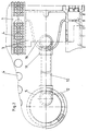
- FIG. 1 part of a suction belt table is shown.
- the suction belt table contains a main suction box 1 over which suction belts 7 are guided.
- the Main suction box 1 has a suction chamber 2, the top side of which by perforated cover plate 3 is limited.
- openings 4 are Passage of suction air provided.
- the suction air acts through the openings 4 Print sheets that are guided on the suction belts 7.
- a suction chamber 9 is provided, which has more Openings 4 is also connected to the suction belts 7.
- the suction belts 7 are moved over pulleys 8 at the end of the table, i.e. beyond the main suction box 1 guided.
- the suction chamber 2 is also with a suction nozzle 5 and with this connected to a fan 6.
- auxiliary suction pipe 12 continues to connect in the suction nozzle 5.
- the auxiliary suction pipe 12 acts as an injector nozzle for additional suction. Functionally, the mode of operation is comparable to a jet pump. Therefore, the auxiliary suction pipe 12 opens into a bend, the suction opening of which faces the fan 6. When pressure is relieved by the suction belt table running free, an increased flow arises in the area of the auxiliary suction pipe 12, which builds up a negative pressure in the auxiliary suction pipe 12.
- the auxiliary suction pipe 12 is connected to the suction chamber 9 via a pipe 10 with a connection 11 and the suction chamber 16. Additional ventilation is provided in the area of the pipe 10.
- the additional ventilation is formed by a ring 13, which is provided with openings 14, which in turn correspond to openings 15 in the tube 10.
- a ring 13 which is provided with openings 14, which in turn correspond to openings 15 in the tube 10.
- FIG 2 the entire arrangement is shown from the top.
- the suction nozzle 5 is shown, into which the suction pipe 12 projects.
- the pipe 10 connects the suction nozzle 5 to the suction chamber 16 in the suction belt table via the Pipe connection 11.
- the auxiliary ventilation is not shown in this case. about the top of the suction belt table, which is formed by the cover plate 3 and is pierced by openings 4, the suction belts 7 with their Suction openings led.
- the suction belt table with its main suction box is 1 in Shown top view and has a first arrangement of cavities 2. in the front area of the suction belt table, i.e. in the area where the arches from Suction belt table run, an additional suction chamber 9 is provided.
- the Suction chamber 9 is connected to suction chamber 16. Furthermore, the suction chamber 9 via openings 17 with the suction space 2, i.e. the main suction box 1 connected.
- the suction belts are placed on the front of the suction belt table Deflection rollers 8 out.
- FIG 3 is a detail of the connection between the suction chamber 9 and the Suction chamber 2 shown in more detail.
- an opening 17 in the Wall between the two cavities 2, 9 closed with a ball 9 become.
- the ball 9 settles in the manner of a check valve for example under spring force in the seat of the opening 17.
- the Ball 9 also have a seat on both sides, so that overpressure regulation can take place between the two cavities 9 and 2.
- the ball 9 can do this against the respective seat by means of a weak spring, which additionally according to a desired overpressure in its preload can be adjustable.
- FIG 4 is a variation of the closure previously described shown between the two cavities 9 and 2.
- the opening 17 is shown between the cover plate 3 and the main suction box 1.
- the opening 17 can through a flap 18 can be closed.
- This flap can be sprung in such a way that they are under an overpressure effect from the side of the suction chamber 9 can be opened. This also applies to an increased vacuum on the Side of the suction room 2.
- the arrangement thus ensures that, for example, when the suction belt table runs empty and there is a pressure increase in the main suction box 1, an undesirable pressure increase or vacuum reduction in the suction space 9 takes place. This could, if necessary, jeopardize the operational safety of the suction belt table when the last sheets run off, which could then no longer be conveyed properly.
- the suction space 16 as a common suction chamber, the air duct to the suction chambers 9 in the end area the suction belt table takes over, the openings 17 of the respective a suction space 9 assigned to a suction belt 7 also directly with the suction space 2 be connected via the pressure compensation devices.
- the Pressure equalization processes can then even be page by page independent run from each other and improve the functionality of the Suction belt table additionally.
Landscapes
- Delivering By Means Of Belts And Rollers (AREA)
- Electrical Discharge Machining, Electrochemical Machining, And Combined Machining (AREA)
- Valve Device For Special Equipments (AREA)
- Belt Conveyors (AREA)
- Sheets, Magazines, And Separation Thereof (AREA)
Abstract
Dazu wird ein Saugraum 9 im Endbereich des Saugbändertisches mittels selbsttätig wirkender Druckausgleichseinrichtungen mit dem Saugraum 2 im Mittelbereich des Saugbändertisches gekoppelt. Die Druckausgleichseinrichtungen wirken so, daß ein höherer Unterdruck im Saugraum 2 diese öffnet und einen unterstützenden Saugluftstrom vom Saugraum 9 zum Saugraum 2 erzeugt.
Description
- Figur 1
- eine Seitenansicht der erfinderischen Vorrichtung,
- Figur 2
- eine Draufsicht auf die erfinderische Vorrichtung,
- Figur 3
- ein Detail aus der erfinderischen Vorrichtung
und - Figur 4
- eine Variante des Details aus der erfinderischen Vorrichtung.
Das Hilfssaugrohr 12 ist über ein Rohr 10 mit einem Anschluß 11 und dem Saugraum 16 an den Saugraum 9 angeschlossen. Im Bereich des Rohres 10 ist eine Zusatzbelüftung vorgesehen. Die Zusatzbelüftung wird gebildet durch einen Ring 13, der mit Öffnungen 14 versehen ist, die wiederum mit Öffnungen 15 in dem Rohr 10 korrespondieren. Durch Verdrehen des gelochten Ringes 15 kann Bypass-Luft in das Rohr 10 geleitet werden und damit der Unterdruck reguliert werden. Schließlich wird der Saugraum 16 mit dem Saugraum 9 mittels einer Öffnung 17 verbunden.
Beim Absaugen der Luft aus dem Hauptsaugkasten 1 mittels des Lüfters 6 wird zusätzlich Luft über die Rohrverbindung 10, 11, 12 zum vorderen Saugraum 9 hin abgesaugt. Wenn sich unterschiedliche Druckverhältnisse einstellen, so daß im Saugraum 2 ein höherer Unterdruck vorhanden ist als im Saugraum 9, können über die in den Figuren 3 und 4 dargestellten Lösungen Druckausgleichsvorgänge stattfinden, indem z.B. die Kugel 19 oder die Klappe 18 die Öffnung 17 freigeben und einen Druckausgleich gestatten. Damit kommt eine unterstützende Wirkung der Absaugung von Luft aus dem Saugraum 2 für den vorderen Saugraum 9 zustande.
Gleichzeitig wird aber durch die Wirkung des Ventiles zwischen den Hohlräumen 2 und 9 verhindert, daß ein erhöhter Unterdruck aus dem Saugraum 9 in den Saugraum 2 übergreifen kann bzw. in den Saugraum 2 abgebaut wird. Die Anordnung stellt damit sicher, daß beispielsweise beim Leerlaufen des Saugbändertisches und einer Druckerhöhung im Hauptsaugkasten 1 eine unerwünschte Druckerhöhung bzw. Unterdruckminderung im Saugraum 9 stattfindet. Dies könnte gegebenenfalls die Betriebssicherheit des Saugbändertisches beim Ablaufen der letzten Bogen in Frage stellen, wobei diese dann nicht mehr einwandfrei gefördert werden könnten.
- 1
- Hauptsaugkasten
- 2
- Saugraum
- 3
- Deckblech
- 4
- Öffnungen
- 5
- Saugstutzen
- 6
- Lüfter
- 7
- Saugband
- 8
- Umlenkrollen
- 9
- Saugraum
- 10
- Rohr
- 11
- Rohranschluß
- 12
- Hilfssaugrohr
- 13
- Ring
- 14
- Öffnung
- 15
- Ring
- 16
- Saugraum
- 17
- Öffnung
- 18
- Klappe
Claims (6)
- Vorrichtung zum Fördern eines unterschuppten Bogenstroms von einer Vereinzelungsvorrichtung zu einer Bogen verarbeitenden Maschine mit einem Saugbändertisch, der zwei unterdruckbeaufschlagbare Kammern aufweist, die in Transportrichtung des Bogenstroms miteinander angeordnet sind, und deren Oberseite die Förderebene des Saugbändertisches bildet, wobei die Kammern in der Förderebene die weiterhin mit Öffnungen versehen sind, über die gleichfalls mit Öffnungen versehene Transportfläche antreibbar geführt sind, mit wenigstens einem Unterdruckerzeuger, vermittels dessen ein Saugluftstrom durch die Kammern und die Öffnungen im Tisch und den Transportbändern erzeugbar ist, wobei zwischen den Kammern verschließbare Öffnungen vorgesehen sind,
dadurch gekennzeichnet,
dass die Öffnung zwischen den Kammern, die als Saugraum (2) im Mittelteil des Saugbändertisches und als Saugraum (16, 9) im Endbereich des Saugbändertisches ausgeführt sind, mit einer bei Druckdifferenz selbsttätig öffnenden Schließeinrichtung versehen sind. - Vorrichtung nach Anspruch 1,
dadurch gekennzeichnet,
dass in einer Trennwand zwischen dem Saugraum (2) und dem Saugraum (9) im Endbereich des Saugbändertisches eine bei im Saugraum (2) anliegendem niedrigerem Druck zu diesem hin öffnende, selbsttätig wirkende Überdruckventileinrichtung vorgesehen ist. - Vorrichtung nach Anspruch 1,
dadurch gekennzeichnet,
dass in einer Trennwand jeweils zwischen dem vom Saugraum (2) getrennten Saugraum (16) und einem jedem Saugband (7) zugeordneten Saugraum (9) im Endbereich des Saugbändertisches eine bei im Saugraum (2) anliegendem niedrigerem Druck zu diesem hin öffnende, selbsttätig wirkende Überdruckventileinrichtung vorgesehen ist. - Vorrichtung nach Anspruch 2 oder 3,
dadurch gekennzeichnet,
dass in der Trennwand zwischen dem Saugraum (2) und dem Saugraum (9) eine Öffnung (17) vorgesehen ist, die mittels einer angefederten Ventilkugel (19) in Richtung zum Saugraum (9) abgedichtet ist. - Vorrichtung nach Anspruch 2 oder 3,
dadurch gekennzeichnet,
dass in der Trennwand zwischen dem Saugraum (2) und dem Saugraum (9) eine Öffnung (17) vorgesehen ist, die mittels einer angefederten Ventilklappe (18) in Richtung zum Saugraum (9) abgedichtet ist. - Vorrichtung nach Anspruch 1 bis 5,
dadurch gekennzeichnet,
dass der Saugraum (2) und der Saugraum (9) mittels einer Rohrverbindung miteinander gekoppelt sind, wobei die Rohrverbindung im Bereich des Lüfters (6) in der Art einer Strahlpumpe in dem Hauptsaugkasten (1) mündet.
Applications Claiming Priority (2)
| Application Number | Priority Date | Filing Date | Title |
|---|---|---|---|
| DE19948067 | 1999-10-06 | ||
| DE19948067A DE19948067A1 (de) | 1999-10-06 | 1999-10-06 | Anlegetisch |
Publications (3)
| Publication Number | Publication Date |
|---|---|
| EP1090863A2 true EP1090863A2 (de) | 2001-04-11 |
| EP1090863A3 EP1090863A3 (de) | 2002-05-08 |
| EP1090863B1 EP1090863B1 (de) | 2004-01-21 |
Family
ID=7924644
Family Applications (1)
| Application Number | Title | Priority Date | Filing Date |
|---|---|---|---|
| EP00118983A Expired - Lifetime EP1090863B1 (de) | 1999-10-06 | 2000-09-01 | Anlegetisch |
Country Status (3)
| Country | Link |
|---|---|
| EP (1) | EP1090863B1 (de) |
| AT (1) | ATE258140T1 (de) |
| DE (2) | DE19948067A1 (de) |
Families Citing this family (1)
| Publication number | Priority date | Publication date | Assignee | Title |
|---|---|---|---|---|
| DE102006061399B4 (de) | 2006-12-23 | 2023-06-22 | Koenig & Bauer Ag | Verfahren zum Zuführen eines geschuppten Bogenstromes |
Family Cites Families (5)
| Publication number | Priority date | Publication date | Assignee | Title |
|---|---|---|---|---|
| DE3001652C2 (de) * | 1980-01-17 | 1984-09-27 | Windmöller & Hölscher, 4540 Lengerich | Saugkanal einer Fördereinrichtung |
| DE4203511A1 (de) * | 1992-02-07 | 1993-08-12 | Roland Man Druckmasch | Vorrichtung zum foerdern eines geschuppten bogenstroms zu einer bogen verarbeitenden maschine |
| DE4442629C2 (de) * | 1994-12-01 | 1998-05-07 | Heidelberger Druckmasch Ag | Saugbändertisch |
| DE19616714A1 (de) * | 1996-04-26 | 1997-11-06 | Heidelberger Druckmasch Ag | Vorrichtung zum Fördern eines insbesondere geschuppten Stroms von Bogen zu einer bogenverarbeitenden Maschine |
| DE19724731A1 (de) * | 1997-06-12 | 1998-12-17 | Roland Man Druckmasch | Anlegetisch |
-
1999
- 1999-10-06 DE DE19948067A patent/DE19948067A1/de not_active Withdrawn
-
2000
- 2000-09-01 AT AT00118983T patent/ATE258140T1/de active
- 2000-09-01 EP EP00118983A patent/EP1090863B1/de not_active Expired - Lifetime
- 2000-09-01 DE DE50005071T patent/DE50005071D1/de not_active Expired - Lifetime
Also Published As
| Publication number | Publication date |
|---|---|
| DE50005071D1 (de) | 2004-02-26 |
| ATE258140T1 (de) | 2004-02-15 |
| DE19948067A1 (de) | 2001-04-19 |
| EP1090863B1 (de) | 2004-01-21 |
| EP1090863A3 (de) | 2002-05-08 |
Similar Documents
| Publication | Publication Date | Title |
|---|---|---|
| EP0454011B1 (de) | Vorrichtung zum Fördern eines insbesondere geschuppten Stroms von Bogen | |
| EP1880960B1 (de) | Vorrichtung zum Zuführen eines geschuppten Bogenstroms | |
| DE10213705B4 (de) | Vorrichtung zum Fördern eines Bogenstroms von einem Bogenstapel zu einer bogenverarbeitenden Maschine | |
| EP0888992B1 (de) | Anlegetisch zum taktmässigen Fördern von Bogen zu einer Bogen verarbeitenden Maschine | |
| DE19817175A1 (de) | Vorrichtung zum Fördern eines insbesondere geschuppten Stroms von Bogen zu einer bogenverarbeitenden Maschine | |
| DE60127431T2 (de) | Vorrichtung zur stapelung von bögen | |
| DE3209259C1 (de) | Bogenanlegevorrichtung an bogenverarbeitenden Maschinen | |
| DE10008909B4 (de) | Vorrichtung zum Separieren eines obersten Blattes von einem Vorratsstapel mittels Luftblasmitteln | |
| DE19616714A1 (de) | Vorrichtung zum Fördern eines insbesondere geschuppten Stroms von Bogen zu einer bogenverarbeitenden Maschine | |
| EP1090863B1 (de) | Anlegetisch | |
| EP1088778B1 (de) | Anlegetisch | |
| EP2620400B1 (de) | Transportsystem zum Transport von Blechtafeln in eine Blechdruckmaschine oder Blechlackiermaschine | |
| DE3220798C1 (de) | Auslegevorrichtung an Bogenrotationsdruckmaschinen | |
| DE19649824A1 (de) | Saugförderer | |
| DE2256246B2 (de) | Automatisches Verschlußorgan für die Saugöffnungen eines Saugförderers | |
| DE19946036B4 (de) | Saugeinrichtung zum seitlichen Ausrichten von Bogen | |
| DE9004967U1 (de) | Vorrichtung zum Fördern eines insbesondere geschuppten Stroms von Bogen | |
| EP1698577B1 (de) | Saugbändertisch | |
| DE102005009223A1 (de) | Saugbändertisch | |
| EP0884259B1 (de) | Anlegetisch | |
| DE102024001304A1 (de) | Verfahren und vorrichutng zur trennung von fraktionen aus einem materialstrom | |
| DE202024000803U1 (de) | Vorrichtung zur Trennung von Fraktionen aus einem Materialstrom | |
| WO2025223591A1 (de) | Verfahren und vorrichtung zur trennung von fraktionen aus einem materialstrom | |
| DE202008018496U1 (de) | Transportsystem sowie Vorrichtung zum Transport von Blechtafeln in eine Blechdruckmaschine oder Blechlackiermaschine | |
| DE202008018495U1 (de) | Blechtafel-Saugvorrichtung und Vorrichtung zum Transport von Blechtafeln in eine Blechdruckmaschine oder Blechlackiermaschine sowie Blechtafel-Transportsystem |
Legal Events
| Date | Code | Title | Description |
|---|---|---|---|
| PUAI | Public reference made under article 153(3) epc to a published international application that has entered the european phase |
Free format text: ORIGINAL CODE: 0009012 |
|
| AK | Designated contracting states |
Kind code of ref document: A2 Designated state(s): AT BE CH CY DE DK ES FI FR GB GR IE IT LI LU MC NL PT SE |
|
| AX | Request for extension of the european patent |
Free format text: AL;LT;LV;MK;RO;SI |
|
| PUAL | Search report despatched |
Free format text: ORIGINAL CODE: 0009013 |
|
| AK | Designated contracting states |
Kind code of ref document: A3 Designated state(s): AT BE CH CY DE DK ES FI FR GB GR IE IT LI LU MC NL PT SE |
|
| AX | Request for extension of the european patent |
Free format text: AL;LT;LV;MK;RO;SI |
|
| RIC1 | Information provided on ipc code assigned before grant |
Free format text: 7B 65H 11/00 A, 7B 65H 5/02 B, 7B 65H 5/22 B |
|
| 17P | Request for examination filed |
Effective date: 20020404 |
|
| AKX | Designation fees paid |
Designated state(s): AT BE CH CY DE DK ES FI FR GB GR IE IT LI LU MC NL PT SE |
|
| 17Q | First examination report despatched |
Effective date: 20030312 |
|
| GRAP | Despatch of communication of intention to grant a patent |
Free format text: ORIGINAL CODE: EPIDOSNIGR1 |
|
| GRAS | Grant fee paid |
Free format text: ORIGINAL CODE: EPIDOSNIGR3 |
|
| GRAA | (expected) grant |
Free format text: ORIGINAL CODE: 0009210 |
|
| AK | Designated contracting states |
Kind code of ref document: B1 Designated state(s): AT BE CH CY DE DK ES FI FR GB GR IE IT LI LU MC NL PT SE |
|
| PG25 | Lapsed in a contracting state [announced via postgrant information from national office to epo] |
Ref country code: CY Free format text: LAPSE BECAUSE OF FAILURE TO SUBMIT A TRANSLATION OF THE DESCRIPTION OR TO PAY THE FEE WITHIN THE PRESCRIBED TIME-LIMIT Effective date: 20040121 Ref country code: FI Free format text: LAPSE BECAUSE OF FAILURE TO SUBMIT A TRANSLATION OF THE DESCRIPTION OR TO PAY THE FEE WITHIN THE PRESCRIBED TIME-LIMIT Effective date: 20040121 Ref country code: IE Free format text: LAPSE BECAUSE OF FAILURE TO SUBMIT A TRANSLATION OF THE DESCRIPTION OR TO PAY THE FEE WITHIN THE PRESCRIBED TIME-LIMIT Effective date: 20040121 Ref country code: NL Free format text: LAPSE BECAUSE OF FAILURE TO SUBMIT A TRANSLATION OF THE DESCRIPTION OR TO PAY THE FEE WITHIN THE PRESCRIBED TIME-LIMIT Effective date: 20040121 |
|
| REG | Reference to a national code |
Ref country code: GB Ref legal event code: FG4D Free format text: NOT ENGLISH |
|
| REG | Reference to a national code |
Ref country code: CH Ref legal event code: EP |
|
| GBT | Gb: translation of ep patent filed (gb section 77(6)(a)/1977) |
Effective date: 20040121 |
|
| REG | Reference to a national code |
Ref country code: IE Ref legal event code: FG4D Free format text: GERMAN |
|
| REF | Corresponds to: |
Ref document number: 50005071 Country of ref document: DE Date of ref document: 20040226 Kind code of ref document: P |
|
| PG25 | Lapsed in a contracting state [announced via postgrant information from national office to epo] |
Ref country code: DK Free format text: LAPSE BECAUSE OF FAILURE TO SUBMIT A TRANSLATION OF THE DESCRIPTION OR TO PAY THE FEE WITHIN THE PRESCRIBED TIME-LIMIT Effective date: 20040421 Ref country code: GR Free format text: LAPSE BECAUSE OF FAILURE TO SUBMIT A TRANSLATION OF THE DESCRIPTION OR TO PAY THE FEE WITHIN THE PRESCRIBED TIME-LIMIT Effective date: 20040421 Ref country code: SE Free format text: LAPSE BECAUSE OF FAILURE TO SUBMIT A TRANSLATION OF THE DESCRIPTION OR TO PAY THE FEE WITHIN THE PRESCRIBED TIME-LIMIT Effective date: 20040421 |
|
| PG25 | Lapsed in a contracting state [announced via postgrant information from national office to epo] |
Ref country code: ES Free format text: LAPSE BECAUSE OF FAILURE TO SUBMIT A TRANSLATION OF THE DESCRIPTION OR TO PAY THE FEE WITHIN THE PRESCRIBED TIME-LIMIT Effective date: 20040502 |
|
| NLV1 | Nl: lapsed or annulled due to failure to fulfill the requirements of art. 29p and 29m of the patents act | ||
| REG | Reference to a national code |
Ref country code: IE Ref legal event code: FD4D |
|
| PG25 | Lapsed in a contracting state [announced via postgrant information from national office to epo] |
Ref country code: LU Free format text: LAPSE BECAUSE OF NON-PAYMENT OF DUE FEES Effective date: 20040901 |
|
| ET | Fr: translation filed | ||
| PG25 | Lapsed in a contracting state [announced via postgrant information from national office to epo] |
Ref country code: CH Free format text: LAPSE BECAUSE OF NON-PAYMENT OF DUE FEES Effective date: 20040930 Ref country code: LI Free format text: LAPSE BECAUSE OF NON-PAYMENT OF DUE FEES Effective date: 20040930 Ref country code: BE Free format text: LAPSE BECAUSE OF NON-PAYMENT OF DUE FEES Effective date: 20040930 Ref country code: MC Free format text: LAPSE BECAUSE OF NON-PAYMENT OF DUE FEES Effective date: 20040930 |
|
| PLBE | No opposition filed within time limit |
Free format text: ORIGINAL CODE: 0009261 |
|
| STAA | Information on the status of an ep patent application or granted ep patent |
Free format text: STATUS: NO OPPOSITION FILED WITHIN TIME LIMIT |
|
| 26N | No opposition filed |
Effective date: 20041022 |
|
| BERE | Be: lapsed |
Owner name: *MAN ROLAND DRUCKMASCHINEN A.G. Effective date: 20040930 |
|
| REG | Reference to a national code |
Ref country code: CH Ref legal event code: PL |
|
| PGFP | Annual fee paid to national office [announced via postgrant information from national office to epo] |
Ref country code: GB Payment date: 20050822 Year of fee payment: 6 |
|
| PGFP | Annual fee paid to national office [announced via postgrant information from national office to epo] |
Ref country code: FR Payment date: 20050823 Year of fee payment: 6 |
|
| PGFP | Annual fee paid to national office [announced via postgrant information from national office to epo] |
Ref country code: IT Payment date: 20060930 Year of fee payment: 7 |
|
| GBPC | Gb: european patent ceased through non-payment of renewal fee |
Effective date: 20060901 |
|
| REG | Reference to a national code |
Ref country code: FR Ref legal event code: ST Effective date: 20070531 |
|
| PG25 | Lapsed in a contracting state [announced via postgrant information from national office to epo] |
Ref country code: GB Free format text: LAPSE BECAUSE OF NON-PAYMENT OF DUE FEES Effective date: 20060901 |
|
| BERE | Be: lapsed |
Owner name: *MAN ROLAND DRUCKMASCHINEN A.G. Effective date: 20040930 |
|
| PG25 | Lapsed in a contracting state [announced via postgrant information from national office to epo] |
Ref country code: PT Free format text: LAPSE BECAUSE OF NON-PAYMENT OF DUE FEES Effective date: 20040621 |
|
| PG25 | Lapsed in a contracting state [announced via postgrant information from national office to epo] |
Ref country code: FR Free format text: LAPSE BECAUSE OF NON-PAYMENT OF DUE FEES Effective date: 20061002 |
|
| PG25 | Lapsed in a contracting state [announced via postgrant information from national office to epo] |
Ref country code: IT Free format text: LAPSE BECAUSE OF NON-PAYMENT OF DUE FEES Effective date: 20070901 |
|
| PGFP | Annual fee paid to national office [announced via postgrant information from national office to epo] |
Ref country code: DE Payment date: 20110923 Year of fee payment: 12 Ref country code: AT Payment date: 20110914 Year of fee payment: 12 |
|
| REG | Reference to a national code |
Ref country code: DE Ref legal event code: R081 Ref document number: 50005071 Country of ref document: DE Owner name: MANROLAND SHEETFED GMBH, DE Free format text: FORMER OWNER: MANROLAND AG, 63075 OFFENBACH, DE Effective date: 20120509 |
|
| REG | Reference to a national code |
Ref country code: AT Ref legal event code: MM01 Ref document number: 258140 Country of ref document: AT Kind code of ref document: T Effective date: 20120901 |
|
| PG25 | Lapsed in a contracting state [announced via postgrant information from national office to epo] |
Ref country code: AT Free format text: LAPSE BECAUSE OF NON-PAYMENT OF DUE FEES Effective date: 20120901 Ref country code: DE Free format text: LAPSE BECAUSE OF NON-PAYMENT OF DUE FEES Effective date: 20130403 |
|
| REG | Reference to a national code |
Ref country code: DE Ref legal event code: R119 Ref document number: 50005071 Country of ref document: DE Effective date: 20130403 |