EP1090610A2 - Assisting-tool for extruding a chemical agent, kneader for preparing and extruding a chemical agent, and methods for using the same - Google Patents
Assisting-tool for extruding a chemical agent, kneader for preparing and extruding a chemical agent, and methods for using the same Download PDFInfo
- Publication number
- EP1090610A2 EP1090610A2 EP00308749A EP00308749A EP1090610A2 EP 1090610 A2 EP1090610 A2 EP 1090610A2 EP 00308749 A EP00308749 A EP 00308749A EP 00308749 A EP00308749 A EP 00308749A EP 1090610 A2 EP1090610 A2 EP 1090610A2
- Authority
- EP
- European Patent Office
- Prior art keywords
- chemical
- chemical agent
- tool
- extruding
- agent
- Prior art date
- Legal status (The legal status is an assumption and is not a legal conclusion. Google has not performed a legal analysis and makes no representation as to the accuracy of the status listed.)
- Granted
Links
Images


Classifications
-
- A—HUMAN NECESSITIES
- A61—MEDICAL OR VETERINARY SCIENCE; HYGIENE
- A61B—DIAGNOSIS; SURGERY; IDENTIFICATION
- A61B17/00—Surgical instruments, devices or methods, e.g. tourniquets
- A61B17/56—Surgical instruments or methods for treatment of bones or joints; Devices specially adapted therefor
- A61B17/58—Surgical instruments or methods for treatment of bones or joints; Devices specially adapted therefor for osteosynthesis, e.g. bone plates, screws, setting implements or the like
- A61B17/88—Osteosynthesis instruments; Methods or means for implanting or extracting internal or external fixation devices
- A61B17/8802—Equipment for handling bone cement or other fluid fillers
- A61B17/8805—Equipment for handling bone cement or other fluid fillers for introducing fluid filler into bone or extracting it
- A61B17/8822—Equipment for handling bone cement or other fluid fillers for introducing fluid filler into bone or extracting it characterised by means facilitating expulsion of fluid from the introducer, e.g. a screw pump plunger, hydraulic force transmissions, application of vibrations or a vacuum
-
- A—HUMAN NECESSITIES
- A61—MEDICAL OR VETERINARY SCIENCE; HYGIENE
- A61M—DEVICES FOR INTRODUCING MEDIA INTO, OR ONTO, THE BODY; DEVICES FOR TRANSDUCING BODY MEDIA OR FOR TAKING MEDIA FROM THE BODY; DEVICES FOR PRODUCING OR ENDING SLEEP OR STUPOR
- A61M5/00—Devices for bringing media into the body in a subcutaneous, intra-vascular or intramuscular way; Accessories therefor, e.g. filling or cleaning devices, arm-rests
- A61M5/178—Syringes
- A61M5/31—Details
- A61M5/315—Pistons; Piston-rods; Guiding, blocking or restricting the movement of the rod or piston; Appliances on the rod for facilitating dosing ; Dosing mechanisms
- A61M5/31533—Dosing mechanisms, i.e. setting a dose
- A61M5/31545—Setting modes for dosing
- A61M5/31548—Mechanically operated dose setting member
- A61M5/3155—Mechanically operated dose setting member by rotational movement of dose setting member, e.g. during setting or filling of a syringe
- A61M5/31551—Mechanically operated dose setting member by rotational movement of dose setting member, e.g. during setting or filling of a syringe including axial movement of dose setting member
-
- A—HUMAN NECESSITIES
- A61—MEDICAL OR VETERINARY SCIENCE; HYGIENE
- A61M—DEVICES FOR INTRODUCING MEDIA INTO, OR ONTO, THE BODY; DEVICES FOR TRANSDUCING BODY MEDIA OR FOR TAKING MEDIA FROM THE BODY; DEVICES FOR PRODUCING OR ENDING SLEEP OR STUPOR
- A61M5/00—Devices for bringing media into the body in a subcutaneous, intra-vascular or intramuscular way; Accessories therefor, e.g. filling or cleaning devices, arm-rests
- A61M5/178—Syringes
- A61M5/31—Details
- A61M5/315—Pistons; Piston-rods; Guiding, blocking or restricting the movement of the rod or piston; Appliances on the rod for facilitating dosing ; Dosing mechanisms
- A61M5/31565—Administration mechanisms, i.e. constructional features, modes of administering a dose
- A61M5/31576—Constructional features or modes of drive mechanisms for piston rods
- A61M5/31578—Constructional features or modes of drive mechanisms for piston rods based on axial translation, i.e. components directly operatively associated and axially moved with plunger rod
- A61M5/3158—Constructional features or modes of drive mechanisms for piston rods based on axial translation, i.e. components directly operatively associated and axially moved with plunger rod performed by axially moving actuator operated by user, e.g. an injection button
-
- B—PERFORMING OPERATIONS; TRANSPORTING
- B01—PHYSICAL OR CHEMICAL PROCESSES OR APPARATUS IN GENERAL
- B01F—MIXING, e.g. DISSOLVING, EMULSIFYING OR DISPERSING
- B01F31/00—Mixers with shaking, oscillating, or vibrating mechanisms
- B01F31/44—Mixers with shaking, oscillating, or vibrating mechanisms with stirrers performing an oscillatory, vibratory or shaking movement
- B01F31/441—Mixers with shaking, oscillating, or vibrating mechanisms with stirrers performing an oscillatory, vibratory or shaking movement performing a rectilinear reciprocating movement
-
- B—PERFORMING OPERATIONS; TRANSPORTING
- B01—PHYSICAL OR CHEMICAL PROCESSES OR APPARATUS IN GENERAL
- B01F—MIXING, e.g. DISSOLVING, EMULSIFYING OR DISPERSING
- B01F33/00—Other mixers; Mixing plants; Combinations of mixers
- B01F33/50—Movable or transportable mixing devices or plants
- B01F33/501—Movable mixing devices, i.e. readily shifted or displaced from one place to another, e.g. portable during use
- B01F33/5011—Movable mixing devices, i.e. readily shifted or displaced from one place to another, e.g. portable during use portable during use, e.g. hand-held
-
- B—PERFORMING OPERATIONS; TRANSPORTING
- B01—PHYSICAL OR CHEMICAL PROCESSES OR APPARATUS IN GENERAL
- B01F—MIXING, e.g. DISSOLVING, EMULSIFYING OR DISPERSING
- B01F35/00—Accessories for mixers; Auxiliary operations or auxiliary devices; Parts or details of general application
- B01F35/75—Discharge mechanisms
- B01F35/754—Discharge mechanisms characterised by the means for discharging the components from the mixer
- B01F35/75425—Discharge mechanisms characterised by the means for discharging the components from the mixer using pistons or plungers
- B01F35/754251—Discharge mechanisms characterised by the means for discharging the components from the mixer using pistons or plungers reciprocating in the mixing receptacle
-
- A—HUMAN NECESSITIES
- A61—MEDICAL OR VETERINARY SCIENCE; HYGIENE
- A61B—DIAGNOSIS; SURGERY; IDENTIFICATION
- A61B50/00—Containers, covers, furniture or holders specially adapted for surgical or diagnostic appliances or instruments, e.g. sterile covers
- A61B2050/005—Containers, covers, furniture or holders specially adapted for surgical or diagnostic appliances or instruments, e.g. sterile covers with a lid or cover
- A61B2050/0066—Containers, covers, furniture or holders specially adapted for surgical or diagnostic appliances or instruments, e.g. sterile covers with a lid or cover with additional sealing means, e.g. O-ring
-
- A—HUMAN NECESSITIES
- A61—MEDICAL OR VETERINARY SCIENCE; HYGIENE
- A61B—DIAGNOSIS; SURGERY; IDENTIFICATION
- A61B50/00—Containers, covers, furniture or holders specially adapted for surgical or diagnostic appliances or instruments, e.g. sterile covers
- A61B50/30—Containers specially adapted for packaging, protecting, dispensing, collecting or disposing of surgical or diagnostic appliances or instruments
- A61B2050/3015—Containers specially adapted for packaging, protecting, dispensing, collecting or disposing of surgical or diagnostic appliances or instruments transparent
-
- A—HUMAN NECESSITIES
- A61—MEDICAL OR VETERINARY SCIENCE; HYGIENE
- A61F—FILTERS IMPLANTABLE INTO BLOOD VESSELS; PROSTHESES; DEVICES PROVIDING PATENCY TO, OR PREVENTING COLLAPSING OF, TUBULAR STRUCTURES OF THE BODY, e.g. STENTS; ORTHOPAEDIC, NURSING OR CONTRACEPTIVE DEVICES; FOMENTATION; TREATMENT OR PROTECTION OF EYES OR EARS; BANDAGES, DRESSINGS OR ABSORBENT PADS; FIRST-AID KITS
- A61F2/00—Filters implantable into blood vessels; Prostheses, i.e. artificial substitutes or replacements for parts of the body; Appliances for connecting them with the body; Devices providing patency to, or preventing collapsing of, tubular structures of the body, e.g. stents
- A61F2/02—Prostheses implantable into the body
- A61F2/30—Joints
- A61F2002/30001—Additional features of subject-matter classified in A61F2/28, A61F2/30 and subgroups thereof
- A61F2002/30316—The prosthesis having different structural features at different locations within the same prosthesis; Connections between prosthetic parts; Special structural features of bone or joint prostheses not otherwise provided for
- A61F2002/30535—Special structural features of bone or joint prostheses not otherwise provided for
- A61F2002/30617—Visible markings for adjusting, locating or measuring
-
- A—HUMAN NECESSITIES
- A61—MEDICAL OR VETERINARY SCIENCE; HYGIENE
- A61F—FILTERS IMPLANTABLE INTO BLOOD VESSELS; PROSTHESES; DEVICES PROVIDING PATENCY TO, OR PREVENTING COLLAPSING OF, TUBULAR STRUCTURES OF THE BODY, e.g. STENTS; ORTHOPAEDIC, NURSING OR CONTRACEPTIVE DEVICES; FOMENTATION; TREATMENT OR PROTECTION OF EYES OR EARS; BANDAGES, DRESSINGS OR ABSORBENT PADS; FIRST-AID KITS
- A61F2250/00—Special features of prostheses classified in groups A61F2/00 - A61F2/26 or A61F2/82 or A61F9/00 or A61F11/00 or subgroups thereof
- A61F2250/0058—Additional features; Implant or prostheses properties not otherwise provided for
- A61F2250/0096—Markers and sensors for detecting a position or changes of a position of an implant, e.g. RF sensors, ultrasound markers
- A61F2250/0097—Visible markings, e.g. indicia
-
- A—HUMAN NECESSITIES
- A61—MEDICAL OR VETERINARY SCIENCE; HYGIENE
- A61M—DEVICES FOR INTRODUCING MEDIA INTO, OR ONTO, THE BODY; DEVICES FOR TRANSDUCING BODY MEDIA OR FOR TAKING MEDIA FROM THE BODY; DEVICES FOR PRODUCING OR ENDING SLEEP OR STUPOR
- A61M5/00—Devices for bringing media into the body in a subcutaneous, intra-vascular or intramuscular way; Accessories therefor, e.g. filling or cleaning devices, arm-rests
- A61M5/178—Syringes
- A61M5/31—Details
- A61M5/315—Pistons; Piston-rods; Guiding, blocking or restricting the movement of the rod or piston; Appliances on the rod for facilitating dosing ; Dosing mechanisms
- A61M5/31533—Dosing mechanisms, i.e. setting a dose
- A61M5/31545—Setting modes for dosing
- A61M5/31548—Mechanically operated dose setting member
- A61M5/31561—Mechanically operated dose setting member using freely adjustable volume steps
-
- A—HUMAN NECESSITIES
- A61—MEDICAL OR VETERINARY SCIENCE; HYGIENE
- A61M—DEVICES FOR INTRODUCING MEDIA INTO, OR ONTO, THE BODY; DEVICES FOR TRANSDUCING BODY MEDIA OR FOR TAKING MEDIA FROM THE BODY; DEVICES FOR PRODUCING OR ENDING SLEEP OR STUPOR
- A61M5/00—Devices for bringing media into the body in a subcutaneous, intra-vascular or intramuscular way; Accessories therefor, e.g. filling or cleaning devices, arm-rests
- A61M5/178—Syringes
- A61M5/31—Details
- A61M5/315—Pistons; Piston-rods; Guiding, blocking or restricting the movement of the rod or piston; Appliances on the rod for facilitating dosing ; Dosing mechanisms
- A61M5/31565—Administration mechanisms, i.e. constructional features, modes of administering a dose
- A61M5/31566—Means improving security or handling thereof
- A61M5/31571—Means preventing accidental administration
-
- A—HUMAN NECESSITIES
- A61—MEDICAL OR VETERINARY SCIENCE; HYGIENE
- A61M—DEVICES FOR INTRODUCING MEDIA INTO, OR ONTO, THE BODY; DEVICES FOR TRANSDUCING BODY MEDIA OR FOR TAKING MEDIA FROM THE BODY; DEVICES FOR PRODUCING OR ENDING SLEEP OR STUPOR
- A61M5/00—Devices for bringing media into the body in a subcutaneous, intra-vascular or intramuscular way; Accessories therefor, e.g. filling or cleaning devices, arm-rests
- A61M5/178—Syringes
- A61M5/31—Details
- A61M5/315—Pistons; Piston-rods; Guiding, blocking or restricting the movement of the rod or piston; Appliances on the rod for facilitating dosing ; Dosing mechanisms
- A61M5/31565—Administration mechanisms, i.e. constructional features, modes of administering a dose
- A61M5/31576—Constructional features or modes of drive mechanisms for piston rods
- A61M5/31583—Constructional features or modes of drive mechanisms for piston rods based on rotational translation, i.e. movement of piston rod is caused by relative rotation between the user activated actuator and the piston rod
- A61M5/31586—Constructional features or modes of drive mechanisms for piston rods based on rotational translation, i.e. movement of piston rod is caused by relative rotation between the user activated actuator and the piston rod performed by rotationally moving or pivoted actuator, e.g. an injection lever or handle
-
- A—HUMAN NECESSITIES
- A61—MEDICAL OR VETERINARY SCIENCE; HYGIENE
- A61M—DEVICES FOR INTRODUCING MEDIA INTO, OR ONTO, THE BODY; DEVICES FOR TRANSDUCING BODY MEDIA OR FOR TAKING MEDIA FROM THE BODY; DEVICES FOR PRODUCING OR ENDING SLEEP OR STUPOR
- A61M5/00—Devices for bringing media into the body in a subcutaneous, intra-vascular or intramuscular way; Accessories therefor, e.g. filling or cleaning devices, arm-rests
- A61M5/178—Syringes
- A61M5/31—Details
- A61M5/315—Pistons; Piston-rods; Guiding, blocking or restricting the movement of the rod or piston; Appliances on the rod for facilitating dosing ; Dosing mechanisms
- A61M5/31565—Administration mechanisms, i.e. constructional features, modes of administering a dose
- A61M5/3159—Dose expelling manners
- A61M5/31591—Single dose, i.e. individually set dose administered only once from the same medicament reservoir, e.g. including single stroke limiting means
-
- B—PERFORMING OPERATIONS; TRANSPORTING
- B01—PHYSICAL OR CHEMICAL PROCESSES OR APPARATUS IN GENERAL
- B01F—MIXING, e.g. DISSOLVING, EMULSIFYING OR DISPERSING
- B01F2101/00—Mixing characterised by the nature of the mixed materials or by the application field
- B01F2101/20—Mixing of ingredients for bone cement
Definitions
- the present invention relates to a chemical-agent extrusion assisting-tool used in extruding a highly viscous chemical agent from a syringe barrel or a similar container through, for example, an injection needle or a catheter, as well as to a method for extruding a chemical agent using the chemical-agent extrusion assisting-tool.
- the chemical-agent extrusion assisting-tool of the present invention facilitates extrusion of a highly viscous chemical agent such as bone cement through, for example, an injection needle connected to a syringe barrel, and is thus useful in filling bone cement, such as calcium-phosphate-based cement, into a defective portion of an organic bone caused by bone fracture or osteoporosis or in applying the same for serving as an adhesive for bonding an artificial bone, formed from metal or ceramic, to an organic bone.
- a highly viscous chemical agent such as bone cement
- bone cement such as calcium-phosphate-based cement
- the invention also relates to a method for extruding a chemical agent using the chemical-agent extrusion assisting-tool, a kneader for use in preparing the chemical agent and to form the container from which the chemical agent is to be extruded using the chemical-agent extrusion assisting-tool. Further, the invention relates to a method for preparing and extruding a chemical-agent using the kneader and the chemical agent extrusion assisting-tool.
- a gun-type ejector for aqueous paste dental materials Japanese Patent Application Laid-Open ( kokai ) No. 7-255748 and PCT International Application Laid-Open NO. W095/00078
- a gun-type ejector for resin-based bone cement such as polymethyl methacrylate
- ejectors particularly the ejector combined with a compressor, are of complicated structure and large size and are thus not readily usable. Since ejectors for extruding bone cement in the course of a surgical operation must be sterilized, they are preferably disposable.
- the ejectors described in the above publications involve a problem in terms of cost and size.
- a gun-type ejector used conventionally for extruding dental materials and resin-based bone cement has an outlet of relatively large diameter and is thus not suited for fine-extrusion applications, such as local filling or application of chemical agent.
- An object of the present invention is to solve the above-mentioned problems involved in the conventional ejectors, and to provide a chemical-agent extrusion assisting-tool enabling extrusion of a highly viscous chemical agent such as calcium-phosphate-based cement through an outlet of small diameter such as an injection needle and capable of being of a disposable type, as well as to provide a method for extruding a chemical agent completely, by use of the assisting tool, from a syringe barrel or a similar container through, for example, an injection needle or catheter connected thereto.
- a chemical-agent extrusion assisting-tool of a first invention is characterized by comprising: a tool body in the form of a cylindrical body having a space formed therein for accommodating a tubular container which contains a chemical agent and which has an outlet formed at its bottom end, the cylindrical body having an annular cylindrical space formed therein in such a manner as to open at an upper end surface thereof; and a pusher comprising a handle portion for pressing a piston to be inserted into the tubular container, and a tubular body disposed on a side of the handle portion which presses the piston, wherein a circumferential surface of the tubular body and a circumferential surface of the cylindrical body which defines the annular cylindrical space are screw-threadedly engaged.
- a second aspect of the invention provides a method for extruding a chemical agent using the chemical-agent extrusion assisting-tool as defined above, characterized by comprising: rotating the handle portion so as to screw-engage the tubular body and the circumferential surface of the cylindrical body which defines the annular cylindrical space and so as thereby to press the piston into the tubular container, thereby extruding the chemical agent from the tubular container.
- the tubular container for containing a chemical agent can be a syringe barrel used generally for filling or applying a chemical agent such as calcium-phosphate-based cement to a required location.
- a chemical agent such as calcium-phosphate-based cement
- a previously prepared chemical agent is filled into the tubular container; and powder and a kneading liquid ⁇ for example, calcium phosphate powder and a kneading liquid for preparation of calcium-phosphate-based cement ⁇ are mixed and kneaded within the tubular container.
- a third aspect of the invention provides a kneader for use as a tubular container with the chemical-agent extrusion assisting-tool according to the first aspect, the kneader comprising: a cylinder to be accommodated in said space formed in the tool body and having a cylindrical portion and a nozzle portion formed at one end of the cylindrical portion; a plug disposed slidably within the cylindrical portion; a piston which includes a shaft portion extending through the plug for rotation relative thereto so as to cause movement of the piston axially of the cylinder, a kneading portion located at an end of the shaft between the plug and the nozzle portion, and a handle portion location at the other end of the shaft for engagement by the pusher; a stopper for releasably holding the plug at the other end of the cylindrical portion; and a cover removably attachable to the nozzle portion.
- a fourth aspect of the invention provides a method for preparing and extruding a chemical agent using the kneader according to the third aspect and the chemical-agent extrusion assisting-tool according to the first aspect, characterized by comprising: introducing constituents to be mixed and kneaded to form the chemical agent into the cylinder of the kneader; turning the handle portion of the piston with the plug fixed by means of the stopper and the cover attached to the nozzle portion so as to rotate and axially move to the kneading portion within the cylindrical portion, and thereby to knead the constituents and form the chemical agent; fitting the cylinder into the space formed in the tool body with the kneading portion returned to said other end of the cylindrical portion adjacent to the plug and removing the cover from the nozzle portion; releasing the stopper; and rotating the handle portion of the pusher so as to screw-engage the circumferential surface of the tubular body and the circumferential surface of the cylindrical body which defines the annular cylindrical space
- the chemical-agent extrusion assisting-tool is useful for extruding those chemicals which the user encounters difficulty in extruding through, for example, an injection needle through pressing with his/her fingers.
- examples of such chemicals include a bone cement and more particularly a calcium-phosphate-based cement.
- Calcium-phosphate-based cement is prepared from calcium phosphate powder and a kneading liquid. After setting, calcium phosphate powder is converted to hydroxyapatite. The thus-formed set substance has sufficient strength to serve as a prosthetic material for bone and exhibits excellent bio-compatibility and bio-activity. Accordingly, calcium-phosphate-based cement is useful for formation of, for example, artificial bone, artificial joints, and artificial tooth roots having excellent strength and bio-activity.
- Examples of calcium phosphate powder include tetracalcium phosphate, calcium hydrogen phosphate, ⁇ -tricalcium phosphate, and ⁇ -tricalcium phosphate . These powders may be used singly or in combination. Calcium phosphate powder may be mixed with X-ray contrast medium, such as barium sulfate or bismuth subcarbonate. In order to shorten setting time, hydroxyapatite or fluoride may be added as seed crystals.
- kneading liquid examples include water, such as pure water, and aqueous solution which contains an appropriate amount of polysaccharide, such as dextran sulfate, organic acid, or inorganic acid.
- a method for accommodating in a tool body of a chemical-agent extrusion assisting-tool a tubular container which contains a chemical agent composed of calcium phosphate powder and a kneading liquid and for extruding the chemical agent from the tubular container will now be described in detail by way of an embodiment.
- a chemical-agent extrusion assisting-tool 1 includes a tool body 2 in the form of a cylindrical body.
- a tubular container 4 is accommodated within a columnar cylindrical space 21 formed in a central portion of the tool body 2.
- the diameter of the space 21 and the outside diameter of the tubular container 4 are determined preferably such that the tubular container 4 can be readily accommodated within the space 21 while sliding on the inner circumferential surface of the cylindrical body and such that the accommodated tubular container 4 is free of play.
- a recess 23 is formed around the upper end edge of the inner circumferential surface defining the space 21. The recess 23 is adapted to prevent the tubular container 4 from slipping out of the space 21.
- the recess 23 assumes a form which corresponds to the shape of a flange of the tubular container 4 and which prevents the tubular container 4 from rotating together with a pusher 3 when the pusher 3 is rotated.
- An annular cylindrical space 22 encircling the columnar cylindrical space 21 opens at the upper end surface of the cylindrical body; i.e., at the end surface of the cylindrical body from which the tubular container 4 is inserted thereinto.
- the annular cylindrical space 22 extends to a predetermined depth longitudinally within the cylindrical body. The predetermined depth is determined such that a piston 5 can be inserted sufficiently into the tubular container 4 to ensure complete extrusion of a chemical agent therefrom.
- the pusher 3 includes a handle portion 31 and a tubular body 32.
- the handle portion 31 and the tubular body 32 may be formed separately and then be fixedly secured together by an appropriate method; for example, through screw engagement or through bonding by means of adhesive. From the viewpoint of strength, however, it is preferable that the handle portion 31 and the tubular body 32 be integrally formed.
- a circumferential surface 321 of the tubular body 32 is screw-threadedly engaged with a circumferential surface 221 of the cylindrical body which defines the cylindrical space 22 of the tool body 2.
- the length of the tubular body 32 is determined preferably such that the piston 5 can be inserted sufficiently into the tubular container 4 to ensure complete extrusion of a chemical agent.
- the side surface of the handle portion 31 is preferably knurled against slip, as shown at 31' in FIG. 4. Since the handle portion 31 of larger diameter requires a smaller force to rotate, it is preferable that the handle portion 31 assume as large a diameter as possible so long as no inconvenience to the user occurs during use.
- the handle portion 31 may assume the form of a disk. However, in order to facilitate rotation and reduce the weight of the pusher 3, the handle portion 31 may assume an apertured form as shown in FIG. 4.
- a circumferential surface of the cylindrical body which defines the annular cylindrical space 22 of the tool body 2 is screw-threadedly engaged with a circumferential surface of the tubular body 32.
- Rotation of the handle portion 31 causes the tubular body 32 to enter the cylindrical space 22 formed in the cylindrical body.
- the piston 5 pressed by the handle portion 31 is inserted into the tubular container 4, thereby extruding a chemical agent.
- Either one of the two circumferential surfaces of the cylindrical body which define the annular cylindrical space 22, and the corresponding inner or outer circumferential surface of the tubular body 32 are threaded.
- Making the pitch of the threads finer reduces a force required to depress the piston 5.
- Making the pitch coarser increases the speed of depressing. Accordingly, the pitch is selected preferably from within a range of 1 to 20 mm, particularly preferably from within a range of 3 to 10 mm, according to, for example, the viscosity of a chemical agent contained in the tubular container 4.
- the material of the tool body 2 and that of the pusher 3 are not particularly limited.
- examples of such materials include resins and metals.
- a synthetic resin which has excellent moldability and which allows the entire tool body 2 to be formed easily and allows the pusher 3 to be formed easily such that the handle portion 31 and the cylindrical portion 32 are integral with each other.
- examples of such a synthetic resin include polyamide; polystyrene; polycarbonate; polyolefin such as polyethylene and polypropylene; polyacetal; polyester; and acrylic resin.
- the amount of extrusion can be estimated by observation of the position and movement of the piston 5 to be inserted into the tubular container 4.
- the tool body 2 and the pusher 3 are formed of a transparent synthetic resin, such as polycarbonate or acrylic resin, so that the amount of extrusion of a chemical agent can be easily confirmed.
- a narrow window 24 may be formed in the side wall of the tool body 2, the size of the window being such as not to affect the strength of the tool body 2, whereby the amount of extrusion can be viewed therethrough.
- graduations may be formed along the window 24 so as to facilitate confirmation of the amount of extrusion.
- different color tones may be imparted to the tool body 2 and the pusher 3 to thereby improve visibility.
- Calcium-phosphate-based cement which has particularly high viscosity, was used as the contents of the tubular container to be extruded.
- An equimolar mixture of tetracalcium phosphate powder and dicalcium phosphate powder was used as calcium phosphate powder.
- Pure water which contained sodium dextran sulfate was used as a kneading liquid.
- the liquid/powder ratio (the amount ratio of kneading liquid to powder) was 0.3 on the basis of weight.
- the mixed powder of calcium phosphate and the kneading liquid were placed in a mortar.
- the resultant mixture was kneaded by means of a pestle.
- the kneaded cement was filled into the syringe barrel.
- the syringe barrel used was a commercially available one having a capacity of 10 milliliters (product of Terumo Corp).
- An injection needle used was a commercially available, disposable Luer-Lok injection needle (18G).
- the syringe barrel was accommodated within the columnar space formed in the tool body.
- a flange portion of the syringe barrel was placed in the recess 23 formed around the upper end edge of the inner circumferential surface of the tool body 2, thereby preventing the syringe barrel from slipping out of the tool body.
- the Luer-Lok injection needle of 18G was connected to an outlet portion of the syringe barrel.
- the tubular body 22 of the pusher was fitted into the annular cylindrical space 22 formed in the tool body through screw engagement.
- the handle portion was rotated so as to advance the tubular body into the annular cylindrical space, thereby pressing the piston 5 into the syringe barrel by means of the handle portion and thus extracting the kneaded cement through the injection needle.
- a specific kneader In place of the commercially available syringe barrel, a specific kneader, to be described below, was used. Calcium phosphate powder and a kneading liquid were mixed and kneaded by use of the kneader, thereby preparing a kneaded cement. Subsequently, the kneader was accommodated within the tool body 2 of the chemical-agent extrusion assisting-tool 1, followed by extrusion of the kneaded cement. Calcium phosphate powder and the kneading liquid were similar to those used in Example 1. The structure of the chemical-agent extrusion assisting-tool was similar to that in the case of Example 1. Dimensions of the chemical-agent extrusion assisting-tool were determined so as to be compatible with the kneader.
- the kneader includes a cylinder 6, a plug 7, a piston 8, a cover 9, and stoppers 10.
- the cylinder 6 includes a cylindrical portion 61 and a nozzle portion 62 formed at one end of the cylindrical portion 61.
- the plug 7 is disposed slidably within the cylindrical portion 61.
- the piston 8 includes a shaft portion 81 extending rotatably through the plug 7 and disposed in a vertically movable manner; a kneading portion 82 located at one end of the shaft portion 81; and a handle portion 83 located at the other end of the shaft portion 81.
- the cover 9 is fitted to an end of the nozzle portion 62 of the cylinder 6.
- the stoppers 10 are adapted to fix the plug 7 at the other end of the cylindrical portion 61.
- the kneading portion 82 includes stirring blades 821 extending laterally and arranged circumferentially.
- the cylinder 6 has a length of about 90 mm and an outside diameter of about 25 mm, and about 10 ml of contents can be kneaded.
- the amount of cement that can be kneaded within the cylinder 6 is preferably equal to or slightly greater than the amount of cement to be consumed in a single phase of treatment (for example, when the amount of cement to be consumed in a single phase of treatment is 10 ml, the amount of cement to be kneaded in the cylinder capacity of 20 ml may be 10-13 ml). If the capacity of the cylinder 6 is less than the amount of cement to be consumed in a single phase of treatment, kneading must be performed several times. If the amount of the cement to be kneaded in the cylinder 6 is in excess of the amount of cement to be consumed in a single phase of treatment, waste of kneaded cement will result.
- the plug 7 assumes a substantially columnar form.
- the plug 7 is inserted into the cylinder 6 through an opening of the cylinder 6 and is fixed in place by means of the stoppers 10.
- Internal threads are formed on the wall surface of a through-hole formed centrally of the plug 7.
- Reception holes for receiving the corresponding stoppers 10 are formed in the side wall of the plug 7.
- Grooves are formed circumferentially in the outer circumferential surface and in the internally-threaded inner circumferential surface of the plug 7.
- O-rings OR1 and OR2 of silicone resin are fitted into the grooves, respectively. The O-rings fitted to sliding portions of the plug 7 prevent escape of the kneaded cement from the kneader and entry of germs into the kneader and facilitates sliding of the plug 7 and rotation of the shaft portion 81.
- the piston 8 includes the shaft portion 81, the kneading portion 82, the stirring blades 821, and the handle portion 83.
- the shaft portion 81 assumes the form of an externally-threaded column.
- the external thread of the shaft portion 81 engages the internal thread of the plug 7, whereby rotation of the shaft portion 81 causes the piston 8 to move vertically within the cylinder 6.
- Rotation of the shaft portion 81 also causes the kneading portion 82 located at one end of the shaft portion 81 to move vertically. Also, when the stoppers 10 are removed, the shaft portion 81 can be moved vertically without rotation to thereby move the plug 7 vertically lengthwise within the cylinder 6.
- the kneading portion 82 is located at an end of the shaft portion 81. As shown in FIGS. 6(a) and 6(b), the kneading portion 82 includes four stirring blades 821, which extend radially from the center of the kneading portion 32.
- the stirring blades 821 may be arranged to incline with respect to the center axis of the kneading portion 82.
- the extension lines of the corresponding stirring blades 821 pass through the center of the kneading portion 82; however, the stirring blades 821 may be arranged such that their extension lines do not pass through the center of the kneading portion 82.
- Each of the stirring blades 821 has a substantially wedge-like section; i.e., the thickness of the stirring blade 821 decreases toward its tip end.
- the shaft portion 81 is externally threaded preferably at a pitch of 5-25 mm, more preferably at a pitch of 6-20 mm, and particularly preferably at a pitch of 7-15 mm. Through use of such a thread pitch range, homogeneously kneaded cement can be easily prepared within a short period of time.
- the number of stirring blades can be 2 to 6, thereby imparting various structures to the kneading portion 82 for efficient kneading.
- the handle portion 83 assumes the form of a disk, the center of which is fixedly attached to the other end of the shaft portion 81.
- the lower surface of the handle portion 31 of the pusher 3 of the chemical-agent extrusion assisting-tool 1 presses the upper surface of the handle portion 83 so as to move the piston 8 and the plug 7 toward the nozzle portion 62 of the cylinder 6, thereby extruding kneaded cement from the cylinder 6.
- the handle portion 83, the shaft portion 81, and the kneading portion 82 may be formed separately and then be fixedly secured together by an appropriate method; for example, through screw engagement or through bonding by means of adhesive. From the viewpoint of strength, however, it is preferable that these members be integrally formed.
- the cover 9 is engaged with a protrusion 621, which is formed on the outer circumferential surface of the nozzle portion 62 of the cylinder 6 and constitutes a Luer-Lok structure.
- the thus-engaged cover 9 prevents escape of the contents of the cylinder 6 while powder and a kneading liquid are mixed and kneaded within the cylinder 6.
- Adapting the nozzle portion 62 to have a Luer-Lok form similar to that employed by a commercially available syringe barrel enables easy attachment to and detachment from the nozzle portion 62 of an injection needle or a catheter for use with a commercially available syringe.
- Each of the stoppers 10 assumes the form of a pin for fixing the plug 7 in place within the cylinder 6 when extrusion is not performed.
- the stoppers 10 are inserted through the corresponding through-holes formed in the side wall of the cylinder 6 and into the corresponding reception holes formed in the side wall of the plug 7, thereby fixing the plug 7 within the cylinder 6 at a predetermined position.
- Two to six equally spaced stoppers 10 can be arranged circumferentially on the cylindrical portion. Particularly, an arrangement of two to four stoppers 10 is preferred.
- This kneader can be easily manufactured and can be stored in a sterile state before use. Thus, the kneader may be used as a disposable instrument.
- the cover 9 was fitted to the nozzle portion 62 so as to engage the protrusion 621, thereby blocking the opening portion of the nozzle portion 62.
- a predetermined amount of a mixed powder of calcium phosphate was placed into the cylinder 6, and then the plug 7 was fixed in place by means of the stoppers 10.
- the plug 7 and the piston 8 were mutually engaged beforehand. Specifically, the shaft portion 81 of the piston 8 was screw-engaged with the internally-threaded portion of the plug 7, and the kneading portion 82 was brought into contact with the plug 7.
- the kneader was irradiated with y rays from outside for sterilization of the contents thereof.
- the cover 9 was removed from the nozzle portion 62 in such a manner as not to cause escape of the mixed powder from the nozzle portion 62.
- a Luer-Lok syringe which contained a kneading liquid was connected to the nozzle portion 62 via a Luer-Lok.
- the kneading liquid was injected into the kneader from the syringe.
- the syringe was disconnected from the nozzle portion 62, and the cover 9 was replaced in an engaged manner to thereby resume blocking the nozzle portion 62.
- the kneader was gently shaken for 10-15 seconds. Then, the handle portion 83 was rotated so as to move the kneading portion 82 to the nozzle portion 62. Subsequently, the handle portion 83 was rotated in the reverse direction so as to move the kneading portion 82 to the plug 7. This reciprocating operation was repeated 3-10 times to thereby knead the mixed powder and the kneading liquid. Since this kneading work was performed within the closed kneader, entry of foreign matter or germs into the cement was prevented.
- the piston 8 was raised until the upper surface of the kneading portion 82 came into contact with the lower surface of the plug 7. Then, the stoppers 10 were removed. Next, a whirl-stop member S shown in FIG. 8 was fitted to a portion of the piston 8 extending between the upper surface of the plug 7 and the lower surface of the handle portion 83, through a longitudinally extending opening portion S1 thereof, to thereby prevent rotation of the piston 8 when the pusher 3 is rotated. Subsequently, the kneader was loaded into the tool body 2 of the chemical-agent extrusion assisting-tool 1, and the cover 9 was removed from the kneader. Calcium-phosphate-based cement was extruded in a manner similar to that of Example 1. As in the case of Example 1, use of the chemical-agent extrusion assisting-tool 1 enabled the user to extrude highly viscous cement ⁇ which could not be extruded simply through pressing with fingers ⁇ easily and completely.
- a protrusion which projects radially inward may be formed at the lower-end edge of the inner circumferential surface of the cylindrical body which defines the space 21, so as to prevent the tubular container 4 from slipping out of the columnar space 21.
- Threads may be formed on the opposite circumferential surfaces of the cylindrical body which define the cylindrical space 22 in the tool body 2, and on both the inner and outer circumferential surfaces of the tubular body 32.
- the above-described structure of the chemical-agent extrusion assisting-tool according to the first aspect of the invention enables the user to extrude a highly viscous chemical agent, such as calcium-phosphate-based cement, through an outlet of small diameter, such as an injection needle or a catheter.
- the chemical-agent extrusion assisting-tool can be of a disposable type, and thus can be used in surgical operations, which require use of sterilized instruments.
- the extrusion method according to the second aspect of the invention enables the user to extrude a highly viscous chemical agent, such as calcium-phosphate-based cement, easily and completely through, for example, an injection needle or a catheter connected to a syringe barrel by use of the chemical-agent extrusion assisting-tool of the first aspect of the invention.
- a highly viscous chemical agent such as calcium-phosphate-based cement
Abstract
Description
- The present invention relates to a chemical-agent extrusion assisting-tool used in extruding a highly viscous chemical agent from a syringe barrel or a similar container through, for example, an injection needle or a catheter, as well as to a method for extruding a chemical agent using the chemical-agent extrusion assisting-tool. The chemical-agent extrusion assisting-tool of the present invention facilitates extrusion of a highly viscous chemical agent such as bone cement through, for example, an injection needle connected to a syringe barrel, and is thus useful in filling bone cement, such as calcium-phosphate-based cement, into a defective portion of an organic bone caused by bone fracture or osteoporosis or in applying the same for serving as an adhesive for bonding an artificial bone, formed from metal or ceramic, to an organic bone. The invention also relates to a method for extruding a chemical agent using the chemical-agent extrusion assisting-tool, a kneader for use in preparing the chemical agent and to form the container from which the chemical agent is to be extruded using the chemical-agent extrusion assisting-tool. Further, the invention relates to a method for preparing and extruding a chemical-agent using the kneader and the chemical agent extrusion assisting-tool.
- A gun-type ejector for aqueous paste dental materials (Japanese Patent Application Laid-Open (kokai) No. 7-255748 and PCT International Application Laid-Open NO. W095/00078) is known as an instrument for extruding through, for example, an injection needle or a catheter, a chemical agent which is so viscous that the user encounters difficulty in extruding through pressing with his/her fingers. There has also been developed a gun-type ejector for resin-based bone cement such as polymethyl methacrylate (PCT International Application Laid-Open NO. W094/16951). Further, there has been proposed an ejector combined with a pressurizing device such as a compressor (Japanese Patent Application Laid-Open (kokai) No. 5-317333) for calcium-phosphate-based cement, which is a highly viscous sludge-like kneaded substance and requires a particularly high pressure in extrusion thereof.
- However, these ejectors, particularly the ejector combined with a compressor, are of complicated structure and large size and are thus not readily usable. Since ejectors for extruding bone cement in the course of a surgical operation must be sterilized, they are preferably disposable. The ejectors described in the above publications involve a problem in terms of cost and size. Further, a gun-type ejector used conventionally for extruding dental materials and resin-based bone cement has an outlet of relatively large diameter and is thus not suited for fine-extrusion applications, such as local filling or application of chemical agent.
- An object of the present invention is to solve the above-mentioned problems involved in the conventional ejectors, and to provide a chemical-agent extrusion assisting-tool enabling extrusion of a highly viscous chemical agent such as calcium-phosphate-based cement through an outlet of small diameter such as an injection needle and capable of being of a disposable type, as well as to provide a method for extruding a chemical agent completely, by use of the assisting tool, from a syringe barrel or a similar container through, for example, an injection needle or catheter connected thereto.
- A chemical-agent extrusion assisting-tool of a first invention is characterized by comprising: a tool body in the form of a cylindrical body having a space formed therein for accommodating a tubular container which contains a chemical agent and which has an outlet formed at its bottom end, the cylindrical body having an annular cylindrical space formed therein in such a manner as to open at an upper end surface thereof; and a pusher comprising a handle portion for pressing a piston to be inserted into the tubular container, and a tubular body disposed on a side of the handle portion which presses the piston, wherein a circumferential surface of the tubular body and a circumferential surface of the cylindrical body which defines the annular cylindrical space are screw-threadedly engaged.
- A second aspect of the invention provides a method for extruding a chemical agent using the chemical-agent extrusion assisting-tool as defined above, characterized by comprising: rotating the handle portion so as to screw-engage the tubular body and the circumferential surface of the cylindrical body which defines the annular cylindrical space and so as thereby to press the piston into the tubular container, thereby extruding the chemical agent from the tubular container.
- The tubular container for containing a chemical agent can be a syringe barrel used generally for filling or applying a chemical agent such as calcium-phosphate-based cement to a required location. Appropriate determination of the diameter and length of the columnar space of the tool body enables use of a container having a certain structure and dimensions, other than general syringe barrels.
- The term "contain" as used herein means the following two cases: a previously prepared chemical agent is filled into the tubular container; and powder and a kneading liquid―for example, calcium phosphate powder and a kneading liquid for preparation of calcium-phosphate-based cement―are mixed and kneaded within the tubular container.
- Thus a third aspect of the invention provides a kneader for use as a tubular container with the chemical-agent extrusion assisting-tool according to the first aspect, the kneader comprising: a cylinder to be accommodated in said space formed in the tool body and having a cylindrical portion and a nozzle portion formed at one end of the cylindrical portion; a plug disposed slidably within the cylindrical portion; a piston which includes a shaft portion extending through the plug for rotation relative thereto so as to cause movement of the piston axially of the cylinder, a kneading portion located at an end of the shaft between the plug and the nozzle portion, and a handle portion location at the other end of the shaft for engagement by the pusher; a stopper for releasably holding the plug at the other end of the cylindrical portion; and a cover removably attachable to the nozzle portion.
- A fourth aspect of the invention provides a method for preparing and extruding a chemical agent using the kneader according to the third aspect and the chemical-agent extrusion assisting-tool according to the first aspect, characterized by comprising: introducing constituents to be mixed and kneaded to form the chemical agent into the cylinder of the kneader; turning the handle portion of the piston with the plug fixed by means of the stopper and the cover attached to the nozzle portion so as to rotate and axially move to the kneading portion within the cylindrical portion, and thereby to knead the constituents and form the chemical agent; fitting the cylinder into the space formed in the tool body with the kneading portion returned to said other end of the cylindrical portion adjacent to the plug and removing the cover from the nozzle portion; releasing the stopper; and rotating the handle portion of the pusher so as to screw-engage the circumferential surface of the tubular body and the circumferential surface of the cylindrical body which defines the annular cylindrical space and so as to thereby cause the pusher to press the piston and the released plug into the tubular container thereby extruding the previously kneaded chemical agent from the kneader.
- The chemical-agent extrusion assisting-tool is useful for extruding those chemicals which the user encounters difficulty in extruding through, for example, an injection needle through pressing with his/her fingers. Examples of such chemicals include a bone cement and more particularly a calcium-phosphate-based cement. Calcium-phosphate-based cement is prepared from calcium phosphate powder and a kneading liquid. After setting, calcium phosphate powder is converted to hydroxyapatite. The thus-formed set substance has sufficient strength to serve as a prosthetic material for bone and exhibits excellent bio-compatibility and bio-activity. Accordingly, calcium-phosphate-based cement is useful for formation of, for example, artificial bone, artificial joints, and artificial tooth roots having excellent strength and bio-activity.
- Examples of calcium phosphate powder include tetracalcium phosphate, calcium hydrogen phosphate, α-tricalcium phosphate, and β-tricalcium phosphate . These powders may be used singly or in combination. Calcium phosphate powder may be mixed with X-ray contrast medium, such as barium sulfate or bismuth subcarbonate. In order to shorten setting time, hydroxyapatite or fluoride may be added as seed crystals.
- Examples of kneading liquid include water, such as pure water, and aqueous solution which contains an appropriate amount of polysaccharide, such as dextran sulfate, organic acid, or inorganic acid.
- The foregoing and other objects, features, aspects and advantages of the present invention will become more apparent from the following detailed description of the present invention when taken in conjunction with the accompanying drawings.
-
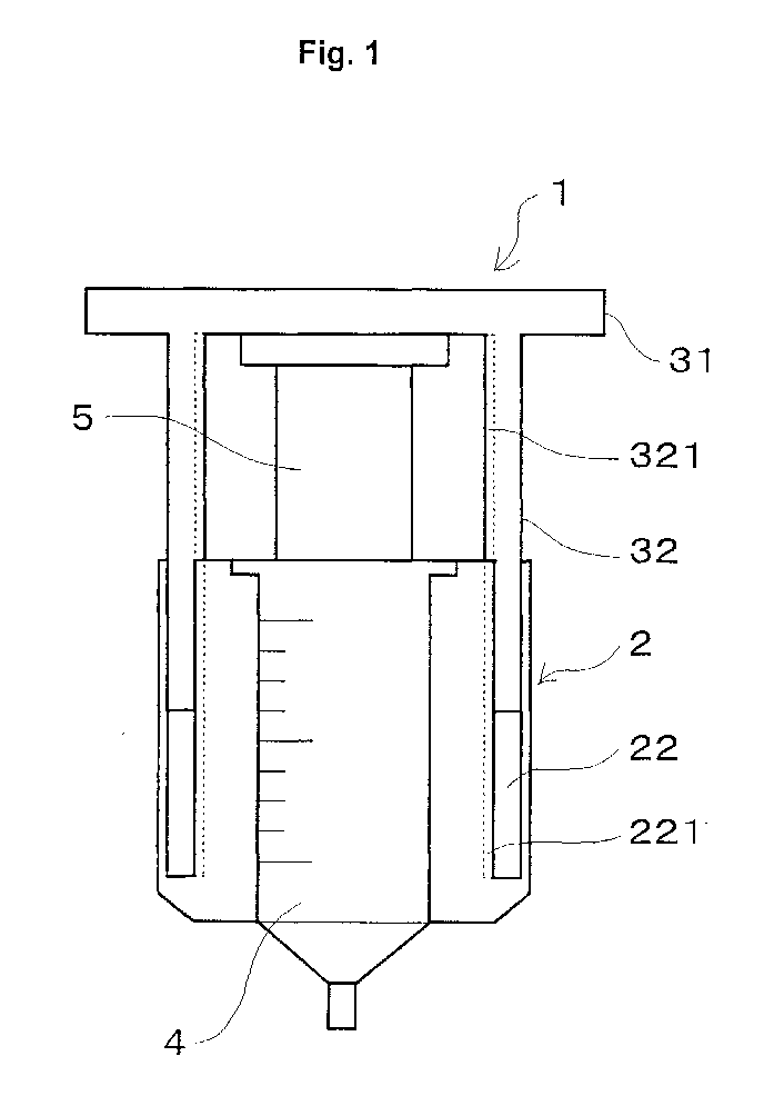
- FIG. 1 is a schematic view of a chemical-agent extrusion assisting-tool in accordance with the invention;
- FIG. 2 is a longitudinal sectional view of a pusher of the chemical-agent extrusion assisting-tool shown in FIG. 1;
- FIG. 3 is a longitudinal sectional view of a tool body of the chemical-agent extrusion assisting-tool shown in FIG. 1;
- FIG. 4 is a top view showing an example of a handle portion of the pusher of FIG. 2;
- FIG. 5 is a front view of a form of the tool body of FIG. 3 having a window formed in its side wall;
- FIG. 6 is a sectional view of a kneader incorporating a stirring blade for kneading calcium-phosphate-based cement;
- FIG.6(a) is a side view showing a portion of the stirring blade of the kneader shown in FIG. 6;
- FIG.6(b) is a sectional view of the stirring blade taken along line I-I of FIG.6(a);
- FIG. 7 is a sectional view showing the kneader of FIG. 6 after having completed extrusion; and
- FIGS. 8(a) and 8(b) are, respectively, plan and front views of a whirl-stop member for preventing rotation of a piston when the pusher is rotated for extrusion of cement.
-
- A method for accommodating in a tool body of a chemical-agent extrusion assisting-tool a tubular container which contains a chemical agent composed of calcium phosphate powder and a kneading liquid and for extruding the chemical agent from the tubular container will now be described in detail by way of an embodiment.
- With reference to Figures 1 to 3, a chemical-agent extrusion assisting-
tool 1 includes atool body 2 in the form of a cylindrical body. Atubular container 4 is accommodated within a columnarcylindrical space 21 formed in a central portion of thetool body 2. The diameter of thespace 21 and the outside diameter of thetubular container 4 are determined preferably such that thetubular container 4 can be readily accommodated within thespace 21 while sliding on the inner circumferential surface of the cylindrical body and such that the accommodatedtubular container 4 is free of play. Preferably, arecess 23 is formed around the upper end edge of the inner circumferential surface defining thespace 21. Therecess 23 is adapted to prevent thetubular container 4 from slipping out of thespace 21. More preferably, therecess 23 assumes a form which corresponds to the shape of a flange of thetubular container 4 and which prevents thetubular container 4 from rotating together with apusher 3 when thepusher 3 is rotated. An annularcylindrical space 22 encircling the columnarcylindrical space 21 opens at the upper end surface of the cylindrical body; i.e., at the end surface of the cylindrical body from which thetubular container 4 is inserted thereinto. The annularcylindrical space 22 extends to a predetermined depth longitudinally within the cylindrical body. The predetermined depth is determined such that apiston 5 can be inserted sufficiently into thetubular container 4 to ensure complete extrusion of a chemical agent therefrom. - The
pusher 3 includes ahandle portion 31 and atubular body 32. Thehandle portion 31 and thetubular body 32 may be formed separately and then be fixedly secured together by an appropriate method; for example, through screw engagement or through bonding by means of adhesive. From the viewpoint of strength, however, it is preferable that thehandle portion 31 and thetubular body 32 be integrally formed. Acircumferential surface 321 of thetubular body 32 is screw-threadedly engaged with acircumferential surface 221 of the cylindrical body which defines thecylindrical space 22 of thetool body 2. As in the case of the depth of thecylindrical space 22, the length of thetubular body 32 is determined preferably such that thepiston 5 can be inserted sufficiently into thetubular container 4 to ensure complete extrusion of a chemical agent. - In order to facilitate rotation, the side surface of the
handle portion 31 is preferably knurled against slip, as shown at 31' in FIG. 4. Since thehandle portion 31 of larger diameter requires a smaller force to rotate, it is preferable that thehandle portion 31 assume as large a diameter as possible so long as no inconvenience to the user occurs during use. Thehandle portion 31 may assume the form of a disk. However, in order to facilitate rotation and reduce the weight of thepusher 3, thehandle portion 31 may assume an apertured form as shown in FIG. 4. - Thus, a circumferential surface of the cylindrical body which defines the annular
cylindrical space 22 of thetool body 2 is screw-threadedly engaged with a circumferential surface of thetubular body 32. Rotation of thehandle portion 31 causes thetubular body 32 to enter thecylindrical space 22 formed in the cylindrical body. Also, thepiston 5 pressed by thehandle portion 31 is inserted into thetubular container 4, thereby extruding a chemical agent. Either one of the two circumferential surfaces of the cylindrical body which define the annularcylindrical space 22, and the corresponding inner or outer circumferential surface of thetubular body 32 are threaded. Making the pitch of the threads finer reduces a force required to depress thepiston 5. Making the pitch coarser increases the speed of depressing. Accordingly, the pitch is selected preferably from within a range of 1 to 20 mm, particularly preferably from within a range of 3 to 10 mm, according to, for example, the viscosity of a chemical agent contained in thetubular container 4. - The material of the
tool body 2 and that of thepusher 3 are not particularly limited. Examples of such materials include resins and metals. Particularly, there is preferred a synthetic resin which has excellent moldability and which allows theentire tool body 2 to be formed easily and allows thepusher 3 to be formed easily such that thehandle portion 31 and thecylindrical portion 32 are integral with each other. Examples of such a synthetic resin include polyamide; polystyrene; polycarbonate; polyolefin such as polyethylene and polypropylene; polyacetal; polyester; and acrylic resin. - In the above-described chemical-agent extrusion assisting-tool, even when the
tool body 2 is opaque, the amount of extrusion can be estimated by observation of the position and movement of thepiston 5 to be inserted into thetubular container 4. Preferably, however, thetool body 2 and thepusher 3 are formed of a transparent synthetic resin, such as polycarbonate or acrylic resin, so that the amount of extrusion of a chemical agent can be easily confirmed. Alternatively, as shown in FIG. 5, anarrow window 24 may be formed in the side wall of thetool body 2, the size of the window being such as not to affect the strength of thetool body 2, whereby the amount of extrusion can be viewed therethrough. Further, graduations may be formed along thewindow 24 so as to facilitate confirmation of the amount of extrusion. Also, different color tones may be imparted to thetool body 2 and thepusher 3 to thereby improve visibility. - Using a commercially available syringe barrel as a tubular container, calcium-phosphate-based cement was extruded according to the following procedure.
- Calcium-phosphate-based cement, which has particularly high viscosity, was used as the contents of the tubular container to be extruded. An equimolar mixture of tetracalcium phosphate powder and dicalcium phosphate powder was used as calcium phosphate powder. Pure water which contained sodium dextran sulfate was used as a kneading liquid. The liquid/powder ratio (the amount ratio of kneading liquid to powder) was 0.3 on the basis of weight.
- First, the mixed powder of calcium phosphate and the kneading liquid were placed in a mortar. The resultant mixture was kneaded by means of a pestle. The kneaded cement was filled into the syringe barrel. The syringe barrel used was a commercially available one having a capacity of 10 milliliters (product of Terumo Corp). An injection needle used was a commercially available, disposable Luer-Lok injection needle (18G). Next, the syringe barrel was accommodated within the columnar space formed in the tool body. A flange portion of the syringe barrel was placed in the
recess 23 formed around the upper end edge of the inner circumferential surface of thetool body 2, thereby preventing the syringe barrel from slipping out of the tool body. Subsequently, the Luer-Lok injection needle of 18G was connected to an outlet portion of the syringe barrel. Then, thetubular body 22 of the pusher was fitted into the annularcylindrical space 22 formed in the tool body through screw engagement. The handle portion was rotated so as to advance the tubular body into the annular cylindrical space, thereby pressing thepiston 5 into the syringe barrel by means of the handle portion and thus extracting the kneaded cement through the injection needle. - Thus, in contrast to a failure to insert the piston when the insertion was attempted by pressing with fingers, use of the described chemical-agent extrusion assisting-tool enabled the user to extrude the kneaded cement very easily. Also, the kneaded cement was extruded completely without remaining within the syringe barrel.
- In place of the commercially available syringe barrel, a specific kneader, to be described below, was used. Calcium phosphate powder and a kneading liquid were mixed and kneaded by use of the kneader, thereby preparing a kneaded cement. Subsequently, the kneader was accommodated within the
tool body 2 of the chemical-agent extrusion assisting-tool 1, followed by extrusion of the kneaded cement. Calcium phosphate powder and the kneading liquid were similar to those used in Example 1. The structure of the chemical-agent extrusion assisting-tool was similar to that in the case of Example 1. Dimensions of the chemical-agent extrusion assisting-tool were determined so as to be compatible with the kneader. - The specific structure of the kneader used in the above Example 2 will next be described with reference to FIGS. 6 and 7.
- The kneader includes a
cylinder 6, aplug 7, apiston 8, acover 9, andstoppers 10. Thecylinder 6 includes acylindrical portion 61 and anozzle portion 62 formed at one end of thecylindrical portion 61. Theplug 7 is disposed slidably within thecylindrical portion 61. Thepiston 8 includes ashaft portion 81 extending rotatably through theplug 7 and disposed in a vertically movable manner; a kneadingportion 82 located at one end of theshaft portion 81; and ahandle portion 83 located at the other end of theshaft portion 81. Thecover 9 is fitted to an end of thenozzle portion 62 of thecylinder 6. Thestoppers 10 are adapted to fix theplug 7 at the other end of thecylindrical portion 61. The kneadingportion 82 includes stirringblades 821 extending laterally and arranged circumferentially. - In the kneader which was actually used, the
cylinder 6 has a length of about 90 mm and an outside diameter of about 25 mm, and about 10 ml of contents can be kneaded. The amount of cement that can be kneaded within thecylinder 6 is preferably equal to or slightly greater than the amount of cement to be consumed in a single phase of treatment (for example, when the amount of cement to be consumed in a single phase of treatment is 10 ml, the amount of cement to be kneaded in the cylinder capacity of 20 ml may be 10-13 ml). If the capacity of thecylinder 6 is less than the amount of cement to be consumed in a single phase of treatment, kneading must be performed several times. If the amount of the cement to be kneaded in thecylinder 6 is in excess of the amount of cement to be consumed in a single phase of treatment, waste of kneaded cement will result. - The
plug 7 assumes a substantially columnar form. Theplug 7 is inserted into thecylinder 6 through an opening of thecylinder 6 and is fixed in place by means of thestoppers 10. Internal threads are formed on the wall surface of a through-hole formed centrally of theplug 7. Reception holes for receiving thecorresponding stoppers 10 are formed in the side wall of theplug 7. Grooves are formed circumferentially in the outer circumferential surface and in the internally-threaded inner circumferential surface of theplug 7. O-rings OR1 and OR2 of silicone resin are fitted into the grooves, respectively. The O-rings fitted to sliding portions of theplug 7 prevent escape of the kneaded cement from the kneader and entry of germs into the kneader and facilitates sliding of theplug 7 and rotation of theshaft portion 81. - The
piston 8 includes theshaft portion 81, the kneadingportion 82, the stirringblades 821, and thehandle portion 83. Theshaft portion 81 assumes the form of an externally-threaded column. The external thread of theshaft portion 81 engages the internal thread of theplug 7, whereby rotation of theshaft portion 81 causes thepiston 8 to move vertically within thecylinder 6. Rotation of theshaft portion 81 also causes the kneadingportion 82 located at one end of theshaft portion 81 to move vertically. Also, when thestoppers 10 are removed, theshaft portion 81 can be moved vertically without rotation to thereby move theplug 7 vertically lengthwise within thecylinder 6. - The kneading
portion 82 is located at an end of theshaft portion 81. As shown in FIGS. 6(a) and 6(b), the kneadingportion 82 includes fourstirring blades 821, which extend radially from the center of the kneadingportion 32. The stirringblades 821 may be arranged to incline with respect to the center axis of the kneadingportion 82. The extension lines of thecorresponding stirring blades 821 pass through the center of the kneadingportion 82; however, the stirringblades 821 may be arranged such that their extension lines do not pass through the center of the kneadingportion 82. Each of thestirring blades 821 has a substantially wedge-like section; i.e., the thickness of thestirring blade 821 decreases toward its tip end. Theshaft portion 81 is externally threaded preferably at a pitch of 5-25 mm, more preferably at a pitch of 6-20 mm, and particularly preferably at a pitch of 7-15 mm. Through use of such a thread pitch range, homogeneously kneaded cement can be easily prepared within a short period of time. The number of stirring blades can be 2 to 6, thereby imparting various structures to the kneadingportion 82 for efficient kneading. - The
handle portion 83 assumes the form of a disk, the center of which is fixedly attached to the other end of theshaft portion 81. With the kneader fitted into the chemical-agent extrusion assisting-tool, the lower surface of thehandle portion 31 of thepusher 3 of the chemical-agent extrusion assisting-tool 1 presses the upper surface of thehandle portion 83 so as to move thepiston 8 and theplug 7 toward thenozzle portion 62 of thecylinder 6, thereby extruding kneaded cement from thecylinder 6. Thehandle portion 83, theshaft portion 81, and the kneadingportion 82 may be formed separately and then be fixedly secured together by an appropriate method; for example, through screw engagement or through bonding by means of adhesive. From the viewpoint of strength, however, it is preferable that these members be integrally formed. - The
cover 9 is engaged with aprotrusion 621, which is formed on the outer circumferential surface of thenozzle portion 62 of thecylinder 6 and constitutes a Luer-Lok structure. The thus-engagedcover 9 prevents escape of the contents of thecylinder 6 while powder and a kneading liquid are mixed and kneaded within thecylinder 6. Adapting thenozzle portion 62 to have a Luer-Lok form similar to that employed by a commercially available syringe barrel enables easy attachment to and detachment from thenozzle portion 62 of an injection needle or a catheter for use with a commercially available syringe. - Each of the
stoppers 10 assumes the form of a pin for fixing theplug 7 in place within thecylinder 6 when extrusion is not performed. Thestoppers 10 are inserted through the corresponding through-holes formed in the side wall of thecylinder 6 and into the corresponding reception holes formed in the side wall of theplug 7, thereby fixing theplug 7 within thecylinder 6 at a predetermined position. Two to six equally spacedstoppers 10 can be arranged circumferentially on the cylindrical portion. Particularly, an arrangement of two to fourstoppers 10 is preferred. - This kneader can be easily manufactured and can be stored in a sterile state before use. Thus, the kneader may be used as a disposable instrument.
- First, in order to prevent escape of the contents of the kneader through the
nozzle portion 62 in the course of kneading, thecover 9 was fitted to thenozzle portion 62 so as to engage theprotrusion 621, thereby blocking the opening portion of thenozzle portion 62. Subsequently, a predetermined amount of a mixed powder of calcium phosphate was placed into thecylinder 6, and then theplug 7 was fixed in place by means of thestoppers 10. Theplug 7 and thepiston 8 were mutually engaged beforehand. Specifically, theshaft portion 81 of thepiston 8 was screw-engaged with the internally-threaded portion of theplug 7, and the kneadingportion 82 was brought into contact with theplug 7. - Next, the kneader was irradiated with y rays from outside for sterilization of the contents thereof. The
cover 9 was removed from thenozzle portion 62 in such a manner as not to cause escape of the mixed powder from thenozzle portion 62. Subsequently, a Luer-Lok syringe which contained a kneading liquid was connected to thenozzle portion 62 via a Luer-Lok. The kneading liquid was injected into the kneader from the syringe. Then, the syringe was disconnected from thenozzle portion 62, and thecover 9 was replaced in an engaged manner to thereby resume blocking thenozzle portion 62. Subsequently, the kneader was gently shaken for 10-15 seconds. Then, thehandle portion 83 was rotated so as to move the kneadingportion 82 to thenozzle portion 62. Subsequently, thehandle portion 83 was rotated in the reverse direction so as to move the kneadingportion 82 to theplug 7. This reciprocating operation was repeated 3-10 times to thereby knead the mixed powder and the kneading liquid. Since this kneading work was performed within the closed kneader, entry of foreign matter or germs into the cement was prevented. - The
piston 8 was raised until the upper surface of the kneadingportion 82 came into contact with the lower surface of theplug 7. Then, thestoppers 10 were removed. Next, a whirl-stop member S shown in FIG. 8 was fitted to a portion of thepiston 8 extending between the upper surface of theplug 7 and the lower surface of thehandle portion 83, through a longitudinally extending opening portion S1 thereof, to thereby prevent rotation of thepiston 8 when thepusher 3 is rotated. Subsequently, the kneader was loaded into thetool body 2 of the chemical-agent extrusion assisting-tool 1, and thecover 9 was removed from the kneader. Calcium-phosphate-based cement was extruded in a manner similar to that of Example 1. As in the case of Example 1, use of the chemical-agent extrusion assisting-tool 1 enabled the user to extrude highly viscous cement―which could not be extruded simply through pressing with fingers―easily and completely. - While the present invention has been described with reference to the above embodiment, the present invention is not limited thereto. The present invention may be embodied in various other specific forms according to purposes or applications without departing from the scope of the invention. For example, a protrusion which projects radially inward may be formed at the lower-end edge of the inner circumferential surface of the cylindrical body which defines the
space 21, so as to prevent thetubular container 4 from slipping out of thecolumnar space 21. Threads may be formed on the opposite circumferential surfaces of the cylindrical body which define thecylindrical space 22 in thetool body 2, and on both the inner and outer circumferential surfaces of thetubular body 32. - The above-described structure of the chemical-agent extrusion assisting-tool according to the first aspect of the invention enables the user to extrude a highly viscous chemical agent, such as calcium-phosphate-based cement, through an outlet of small diameter, such as an injection needle or a catheter. The chemical-agent extrusion assisting-tool can be of a disposable type, and thus can be used in surgical operations, which require use of sterilized instruments.
- The extrusion method according to the second aspect of the invention enables the user to extrude a highly viscous chemical agent, such as calcium-phosphate-based cement, easily and completely through, for example, an injection needle or a catheter connected to a syringe barrel by use of the chemical-agent extrusion assisting-tool of the first aspect of the invention.
Claims (8)
- A chemical-agent extrusion assisting-tool characterized by comprising:wherein a circumferential surface of the tubular body and a circumferential surface of the cylindrical body which defines the annular cylindrical space are screw-threadedly engaged.a tool body in the form of a cylindrical body having a space formed therein for accommodating a tubular container which contains a chemical agent and which has an outlet formed at its bottom end, the cylindrical body having an annular cylindrical space formed therein in such a manner as to open at an upper end surface thereof; anda pusher comprising a handle portion for pressing a piston to be inserted into the tubular container, and a tubular body disposed on a side of the handle portion which presses the piston;
- A method for extruding a chemical agent using the chemical-agent extrusion assisting-tool according to claim 1, characterized by comprising: rotating the handle portion so as to screw-engage the circumferential surface of the tubular body and the circumferential surface of the cylindrical body which defines the annular cylindrical space and so as to thereby press the piston into the tubular container, thereby extruding the chemical agent from the tubular container.
- A method for extruding a chemical agent according to claim 2, wherein the chemical agent comprises bone cement.
- A method for extruding a chemical agent according to claim 3, wherein the bone cement comprises calcium-phosphate-based cement.
- A kneader for use as a tubular container with the chemical-agent extrusion assisting-tool according to claim 1, the kneader comprising:a cylinder to be accommodated in said space formed in the tool body and having a cylindrical portion and a nozzle portion formed at one end of the cylindrical portion;a plug disposed slidably within the cylindrical portion;a piston which includes a shaft portion extending through the plug for rotation relative thereto so as to cause movement of the piston axially of the cylinder, a kneading portion located at an end of the shaft between the plug and the nozzle portion, and a handle portion location at the other end of the shaft for engagement by the pusher;a stopper for releasably holding the plug at the other end of the cylindrical portion; anda cover removably attachable to the nozzle portion.
- A method for preparing and extruding a chemical agent using the kneader according to claim 5 and the chemical-agent extrusion assisting-tool according to claim 1, characterized by comprising:introducing constituents to be mixed and kneaded to form the chemical agent into the cylinder of the kneader;turning the handle portion of the piston with the plug fixed by means of the stopper and the cover attached to the nozzle portion so as to rotate and axially move to the kneading portion within the cylindrical portion, and thereby to knead the constituents and form the chemical agent;fitting the cylinder into the space formed in the tool body with the kneading portion returned to said other end of the cylindrical portion adjacent to the plug and removing the cover from the nozzle portion;releasing the stopper; androtating the handle portion of the pusher so as to screw-engage the circumferential surface of the tubular body and the circumferential surface of the cylindrical body which defines the annular cylindrical space and so as to thereby cause the pusher to press the piston and the released plug into the tubular container thereby extruding the previously kneaded chemical agent from the kneader.
- A method for preparing and extruding a chemical agent according to claim 6, wherein the chemical agent comprises bone cement.
- A method for preparing and extruding a chemical agent according to claim 7, wherein the bone cement comprises calcium-phosphate-based cement.
Priority Applications (1)
| Application Number | Priority Date | Filing Date | Title |
|---|---|---|---|
| EP04075904A EP1433446B1 (en) | 1999-10-06 | 2000-10-04 | Assisting-tool for extruding a chemical agent, kneader for preparing and extruding a chemical agent, and methods for using the same |
Applications Claiming Priority (2)
| Application Number | Priority Date | Filing Date | Title |
|---|---|---|---|
| JP28591999 | 1999-10-06 | ||
| JP28591999A JP2001104324A (en) | 1999-10-06 | 1999-10-06 | Medicine extruding auxiliary device, and medicine extruding method using the same |
Related Child Applications (1)
| Application Number | Title | Priority Date | Filing Date |
|---|---|---|---|
| EP04075904A Division EP1433446B1 (en) | 1999-10-06 | 2000-10-04 | Assisting-tool for extruding a chemical agent, kneader for preparing and extruding a chemical agent, and methods for using the same |
Publications (3)
| Publication Number | Publication Date |
|---|---|
| EP1090610A2 true EP1090610A2 (en) | 2001-04-11 |
| EP1090610A3 EP1090610A3 (en) | 2001-11-21 |
| EP1090610B1 EP1090610B1 (en) | 2005-02-09 |
Family
ID=17697725
Family Applications (2)
| Application Number | Title | Priority Date | Filing Date |
|---|---|---|---|
| EP04075904A Expired - Lifetime EP1433446B1 (en) | 1999-10-06 | 2000-10-04 | Assisting-tool for extruding a chemical agent, kneader for preparing and extruding a chemical agent, and methods for using the same |
| EP00308749A Expired - Lifetime EP1090610B1 (en) | 1999-10-06 | 2000-10-04 | Assisting-tool for extruding a chemical agent and method for using the same |
Family Applications Before (1)
| Application Number | Title | Priority Date | Filing Date |
|---|---|---|---|
| EP04075904A Expired - Lifetime EP1433446B1 (en) | 1999-10-06 | 2000-10-04 | Assisting-tool for extruding a chemical agent, kneader for preparing and extruding a chemical agent, and methods for using the same |
Country Status (4)
| Country | Link |
|---|---|
| US (2) | US6431743B1 (en) |
| EP (2) | EP1433446B1 (en) |
| JP (1) | JP2001104324A (en) |
| DE (2) | DE60021633T2 (en) |
Cited By (5)
| Publication number | Priority date | Publication date | Assignee | Title |
|---|---|---|---|---|
| EP1090609A1 (en) * | 1999-10-07 | 2001-04-11 | NGK Spark Plug Company Limited | Device and method for preparing calcium phosphate-based cement |
| WO2006118884A2 (en) * | 2005-04-29 | 2006-11-09 | Wyeth | Drug delivery devices and related components, systems and methods |
| WO2016071483A1 (en) * | 2014-11-06 | 2016-05-12 | Vetter Pharma-Fertigung GmbH & Co. KG | Medicament device |
| EP2777575B1 (en) * | 2013-03-13 | 2017-11-15 | Nordson Corporation | Assembly for dispensing biomaterial |
| US11723757B2 (en) | 2015-05-29 | 2023-08-15 | 3M Innovative Properties Company | Dental material dispensing device and a method of dispensing a dental material |
Families Citing this family (78)
| Publication number | Priority date | Publication date | Assignee | Title |
|---|---|---|---|---|
| JP2001104324A (en) * | 1999-10-06 | 2001-04-17 | Ngk Spark Plug Co Ltd | Medicine extruding auxiliary device, and medicine extruding method using the same |
| US6702821B2 (en) | 2000-01-14 | 2004-03-09 | The Bonutti 2003 Trust A | Instrumentation for minimally invasive joint replacement and methods for using same |
| US7635390B1 (en) | 2000-01-14 | 2009-12-22 | Marctec, Llc | Joint replacement component having a modular articulating surface |
| US6770078B2 (en) | 2000-01-14 | 2004-08-03 | Peter M. Bonutti | Movable knee implant and methods therefor |
| SE520688C2 (en) * | 2000-04-11 | 2003-08-12 | Bone Support Ab | An injectable bone mineral replacement material |
| SE517168C2 (en) * | 2000-07-17 | 2002-04-23 | Bone Support Ab | A composition for an injectable bone mineral replacement material |
| US6712794B2 (en) * | 2001-08-21 | 2004-03-30 | Spinal Specialties, Inc. | Apparatus for delivering a viscous liquid to a surgical site |
| US7708741B1 (en) | 2001-08-28 | 2010-05-04 | Marctec, Llc | Method of preparing bones for knee replacement surgery |
| US7029163B2 (en) * | 2002-10-07 | 2006-04-18 | Advanced Biomaterial Systems, Inc. | Apparatus for mixing and dispensing components |
| SE522098C2 (en) * | 2001-12-20 | 2004-01-13 | Bone Support Ab | Artificial bone mineral substitute material useful as an X-ray contrast medium comprises ceramic and water soluble non-ionic X-ray contrast agent |
| SE524714C2 (en) * | 2002-06-28 | 2004-09-21 | Asept Medical Ab | Bone cement processor and applicator |
| US7887542B2 (en) | 2003-01-15 | 2011-02-15 | Biomet Manufacturing Corp. | Method and apparatus for less invasive knee resection |
| US8551100B2 (en) | 2003-01-15 | 2013-10-08 | Biomet Manufacturing, Llc | Instrumentation for knee resection |
| US7789885B2 (en) | 2003-01-15 | 2010-09-07 | Biomet Manufacturing Corp. | Instrumentation for knee resection |
| US7837690B2 (en) | 2003-01-15 | 2010-11-23 | Biomet Manufacturing Corp. | Method and apparatus for less invasive knee resection |
| US7153454B2 (en) * | 2003-01-21 | 2006-12-26 | University Of Southern California | Multi-nozzle assembly for extrusion of wall |
| JP4191507B2 (en) * | 2003-02-24 | 2008-12-03 | 日本特殊陶業株式会社 | Medical paste kneading injector and medical paste kneading injector material |
| SE0300620D0 (en) * | 2003-03-05 | 2003-03-05 | Bone Support Ab | A new bone substitute composition |
| EP2311408B1 (en) | 2003-03-14 | 2019-02-20 | DePuy Spine, Inc. | Hydraulic device for injection of bone cement in percutaneous vertebroplasty |
| US8066713B2 (en) | 2003-03-31 | 2011-11-29 | Depuy Spine, Inc. | Remotely-activated vertebroplasty injection device |
| US7252212B2 (en) * | 2003-05-01 | 2007-08-07 | Muniswamappa Anjanappa | Long-term liquid storage and dispensing system |
| US8415407B2 (en) | 2004-03-21 | 2013-04-09 | Depuy Spine, Inc. | Methods, materials, and apparatus for treating bone and other tissue |
| US20050060100A1 (en) * | 2003-09-15 | 2005-03-17 | Becton Dickinson And Company | Computer software and algorithms for systems biologically linked to cellular phenotype |
| US8579908B2 (en) | 2003-09-26 | 2013-11-12 | DePuy Synthes Products, LLC. | Device for delivering viscous material |
| SE0302983D0 (en) * | 2003-11-11 | 2003-11-11 | Bone Support Ab | Apparatus for providing spongy bone with bone replacement and / or bone strengthening material and associated method |
| US7524103B2 (en) * | 2003-11-18 | 2009-04-28 | Boston Scientific Scimed, Inc. | Apparatus for mixing and dispensing a multi-component bone cement |
| US7488324B1 (en) | 2003-12-08 | 2009-02-10 | Biomet Manufacturing Corporation | Femoral guide for implanting a femoral knee prosthesis |
| US20050222538A1 (en) * | 2004-03-30 | 2005-10-06 | Sdgi Holdings, Inc. | Surgical system for delivery of viscous fluids |
| SE527528C2 (en) | 2004-06-22 | 2006-04-04 | Bone Support Ab | Apparatus for the preparation of curable pulp and use of the apparatus |
| CN101065080B (en) | 2004-07-30 | 2021-10-29 | 德普伊新特斯产品有限责任公司 | Materials and instruments for treating bone and other tissue |
| US20080319445A9 (en) * | 2004-08-17 | 2008-12-25 | Scimed Life Systems, Inc. | Apparatus and methods for delivering compounds into vertebrae for vertebroplasty |
| US8038682B2 (en) * | 2004-08-17 | 2011-10-18 | Boston Scientific Scimed, Inc. | Apparatus and methods for delivering compounds into vertebrae for vertebroplasty |
| US7357789B2 (en) * | 2004-11-23 | 2008-04-15 | Ultradent Products, Inc. | Specially designed syringes for dispensing granular or powdered solids |
| US7261559B2 (en) * | 2005-04-01 | 2007-08-28 | Ultradent Products, Inc. | Syringe delivery system for dispensing a dental composite or other highly viscous material |
| US7695479B1 (en) | 2005-04-12 | 2010-04-13 | Biomet Manufacturing Corp. | Femoral sizer |
| US9381024B2 (en) | 2005-07-31 | 2016-07-05 | DePuy Synthes Products, Inc. | Marked tools |
| US9918767B2 (en) | 2005-08-01 | 2018-03-20 | DePuy Synthes Products, Inc. | Temperature control system |
| US7249879B2 (en) * | 2005-08-04 | 2007-07-31 | Yunes Nabilsi | Easy pour blender |
| US8360629B2 (en) | 2005-11-22 | 2013-01-29 | Depuy Spine, Inc. | Mixing apparatus having central and planetary mixing elements |
| US9173661B2 (en) | 2006-02-27 | 2015-11-03 | Biomet Manufacturing, Llc | Patient specific alignment guide with cutting surface and laser indicator |
| US8070752B2 (en) | 2006-02-27 | 2011-12-06 | Biomet Manufacturing Corp. | Patient specific alignment guide and inter-operative adjustment |
| US9345548B2 (en) | 2006-02-27 | 2016-05-24 | Biomet Manufacturing, Llc | Patient-specific pre-operative planning |
| US8591516B2 (en) | 2006-02-27 | 2013-11-26 | Biomet Manufacturing, Llc | Patient-specific orthopedic instruments |
| US7780672B2 (en) | 2006-02-27 | 2010-08-24 | Biomet Manufacturing Corp. | Femoral adjustment device and associated method |
| US9289253B2 (en) | 2006-02-27 | 2016-03-22 | Biomet Manufacturing, Llc | Patient-specific shoulder guide |
| US10278711B2 (en) | 2006-02-27 | 2019-05-07 | Biomet Manufacturing, Llc | Patient-specific femoral guide |
| US9907659B2 (en) | 2007-04-17 | 2018-03-06 | Biomet Manufacturing, Llc | Method and apparatus for manufacturing an implant |
| US9918740B2 (en) | 2006-02-27 | 2018-03-20 | Biomet Manufacturing, Llc | Backup surgical instrument system and method |
| US8407067B2 (en) | 2007-04-17 | 2013-03-26 | Biomet Manufacturing Corp. | Method and apparatus for manufacturing an implant |
| US8603180B2 (en) | 2006-02-27 | 2013-12-10 | Biomet Manufacturing, Llc | Patient-specific acetabular alignment guides |
| US9113971B2 (en) | 2006-02-27 | 2015-08-25 | Biomet Manufacturing, Llc | Femoral acetabular impingement guide |
| US20150335438A1 (en) | 2006-02-27 | 2015-11-26 | Biomet Manufacturing, Llc. | Patient-specific augments |
| US9339278B2 (en) | 2006-02-27 | 2016-05-17 | Biomet Manufacturing, Llc | Patient-specific acetabular guides and associated instruments |
| US7704253B2 (en) * | 2006-03-06 | 2010-04-27 | Howmedica Osteonics Corp. | Single use resection guide |
| US7695520B2 (en) | 2006-05-31 | 2010-04-13 | Biomet Manufacturing Corp. | Prosthesis and implementation system |
| US9795399B2 (en) | 2006-06-09 | 2017-10-24 | Biomet Manufacturing, Llc | Patient-specific knee alignment guide and associated method |
| US8096449B2 (en) | 2006-07-17 | 2012-01-17 | Medmix Systems Ag | Dispensing appliance for a multiple cartridge |
| EP2068898A4 (en) | 2006-09-14 | 2011-07-20 | Depuy Spine Inc | Bone cement and methods of use thereof |
| CA2665995C (en) | 2006-10-19 | 2011-11-29 | Oren Globerman | Fluid delivery system |
| US8534908B2 (en) * | 2007-04-20 | 2013-09-17 | Handi-Craft Company | Pitcher having mixing device |
| DE102008030623A1 (en) * | 2008-01-03 | 2009-07-09 | Umsonst-Kübler, Petra | Device for mixing a mass |
| CN101909527A (en) * | 2008-01-11 | 2010-12-08 | 药物混合系统股份公司 | Dispensing appliance for a multiple cartridge |
| DK2328643T3 (en) | 2008-09-29 | 2019-03-04 | Lidds Ab | INJECTION DEVICE WITH MIXING ELEMENT |
| US8653029B2 (en) | 2009-07-30 | 2014-02-18 | Warsaw Orthopedic, Inc. | Flowable paste and putty bone void filler |
| ES2871777T3 (en) * | 2009-12-23 | 2021-11-02 | Becton Dickinson Co | Nasal single-dose medication delivery device |
| US9180137B2 (en) | 2010-02-09 | 2015-11-10 | Bone Support Ab | Preparation of bone cement compositions |
| US9050414B2 (en) * | 2010-02-19 | 2015-06-09 | Cardiovascular Systems, Inc. | Systems and methods for mixing therapeutic agents before and/or during administration |
| CA2736841C (en) | 2010-04-15 | 2014-02-18 | Teneo Innovations Inc. | Device and electronic controller for syringe piston control |
| US9968376B2 (en) | 2010-11-29 | 2018-05-15 | Biomet Manufacturing, Llc | Patient-specific orthopedic instruments |
| US9241745B2 (en) | 2011-03-07 | 2016-01-26 | Biomet Manufacturing, Llc | Patient-specific femoral version guide |
| DE102011078651A1 (en) * | 2011-07-05 | 2013-01-10 | Robert Bosch Gmbh | Method for producing at least one through-hole and apparatus for carrying out such a method |
| ES2421545B1 (en) * | 2012-02-01 | 2014-06-25 | Universitat Polit�Cnica De Catalunya | BODY CEMENT DOSAGE AND INJECTION DEVICE |
| EP2914190B1 (en) | 2012-11-02 | 2017-04-12 | Cook Medical Technologies LLC | Controlled injection systems |
| ES2671122T3 (en) | 2013-02-20 | 2018-06-05 | Bone Support Ab | Enhanced hardening of hardenable bone substitute |
| US9956384B2 (en) | 2014-01-24 | 2018-05-01 | Cook Medical Technologies Llc | Articulating balloon catheter and method for using the same |
| US10722310B2 (en) | 2017-03-13 | 2020-07-28 | Zimmer Biomet CMF and Thoracic, LLC | Virtual surgery planning system and method |
| US10758287B2 (en) | 2018-09-13 | 2020-09-01 | Warsaw Orthopedic, Inc. | Bone material mixing and dispensing devices and methods |
| US11241330B1 (en) | 2021-04-02 | 2022-02-08 | Brixton Biosciences, Inc. | Apparatus for creation of injectable slurry |
Citations (4)
| Publication number | Priority date | Publication date | Assignee | Title |
|---|---|---|---|---|
| JPH05317333A (en) | 1992-05-18 | 1993-12-03 | Mitsubishi Materials Corp | Biomedical cement filling device |
| WO1994016951A1 (en) | 1993-01-29 | 1994-08-04 | Biomet, Inc. | Method and apparatus for packaging, mixing and delivering bone cement |
| WO1995000078A1 (en) | 1993-06-28 | 1995-01-05 | Centrix, Inc. | Dental syringe and cartridge therefor |
| JPH07255748A (en) | 1994-02-28 | 1995-10-09 | Minnesota Mining & Mfg Co <3M> | Delivery system for aqueous paste dental material |
Family Cites Families (26)
| Publication number | Priority date | Publication date | Assignee | Title |
|---|---|---|---|---|
| US2250467A (en) * | 1939-02-08 | 1941-07-29 | Samuel F Cole | Syringe |
| US3140078A (en) * | 1961-06-15 | 1964-07-07 | Adhesive Eng Co | Mixing and dispensing device |
| US3417971A (en) | 1967-02-23 | 1968-12-24 | Robert J. Blank | Mixing and ejection tool |
| US3724077A (en) | 1971-11-26 | 1973-04-03 | Unitek Corp | Mixing syringe |
| DE3425566A1 (en) | 1984-07-11 | 1986-01-16 | Draenert Klaus | DEVICE AND METHOD FOR MIXING AND APPLYING BONE CEMENT |
| WO1986006618A1 (en) | 1985-05-14 | 1986-11-20 | Labor Für Experimentelle Chirurgie | Method and apparatus for preparaing a self-curing two component powder/liquid cement |
| US4751921A (en) | 1985-10-21 | 1988-06-21 | University Of Iowa Research Foundation | Bone cement syringe |
| DE3708803A1 (en) * | 1987-03-18 | 1988-09-29 | Fischbach A Kunststoff Kg | MIXING DEVICE FOR PASTOESE MULTI-COMPONENT DIMENSIONS |
| IL86799A (en) * | 1987-07-02 | 1993-03-15 | Kabi Pharmacia Ab | Method and device for injection |
| US4906231A (en) * | 1988-10-14 | 1990-03-06 | Young J Winslow | Single-use fillable syringe |
| US5071040A (en) | 1990-03-09 | 1991-12-10 | Pfizer Hospital Products Group, Inc. | Surgical adhesives mixing and dispensing implement |
| DE4022986C2 (en) | 1990-07-19 | 2002-10-24 | Hahn Michael | Device for applying bone cement |
| US5186563A (en) * | 1991-01-07 | 1993-02-16 | Gebhard Patricia A | Fluid dispenser with applicator member |
| FR2716375B3 (en) | 1994-02-23 | 1996-05-24 | Alain Villette | Medical injector. |
| FR2720268B1 (en) | 1994-05-24 | 1996-10-25 | Implants Orthopediques Toutes | Femoral stem for hip prosthesis. |
| DE4425218A1 (en) | 1994-07-16 | 1996-01-18 | Merck Patent Gmbh | Device for mixing and discharging bone cement |
| US5588745A (en) * | 1994-09-02 | 1996-12-31 | Howmedica | Methods and apparatus for mixing bone cement components using an evacuated mixing chamber |
| DE19522451C2 (en) * | 1995-06-21 | 1997-11-06 | Bernd Hansen | Device for dispensing a flowable substance from a container |
| DE19532015A1 (en) | 1995-08-31 | 1997-03-06 | Alfred Von Schuckmann | Device for mixing and dispensing multi-component products |
| GB9525209D0 (en) | 1995-12-09 | 1996-02-07 | Depuy Int Ltd | Mixing bone cement |
| US5876116A (en) * | 1996-11-15 | 1999-03-02 | Barker; Donald | Integrated bone cement mixing and dispensing system |
| US5954689A (en) * | 1996-12-20 | 1999-09-21 | Novo Nordisk A/S | Jet injector |
| US5842786A (en) * | 1997-03-07 | 1998-12-01 | Solomon; Alan | Method and device for mixing medical compositions |
| GB2338428A (en) | 1998-06-19 | 1999-12-22 | David Grant | A syringe with an agitator whose shaft passes through a slidable dispensing plunger |
| US6086594A (en) | 1998-10-16 | 2000-07-11 | Brown; Byron L. | Cement pressurizing device |
| JP2001104324A (en) * | 1999-10-06 | 2001-04-17 | Ngk Spark Plug Co Ltd | Medicine extruding auxiliary device, and medicine extruding method using the same |
-
1999
- 1999-10-06 JP JP28591999A patent/JP2001104324A/en active Pending
-
2000
- 2000-10-03 US US09/678,399 patent/US6431743B1/en not_active Expired - Fee Related
- 2000-10-04 EP EP04075904A patent/EP1433446B1/en not_active Expired - Lifetime
- 2000-10-04 EP EP00308749A patent/EP1090610B1/en not_active Expired - Lifetime
- 2000-10-04 DE DE60021633T patent/DE60021633T2/en not_active Expired - Lifetime
- 2000-10-04 DE DE60018003T patent/DE60018003T2/en not_active Expired - Fee Related
-
2002
- 2002-07-01 US US10/184,966 patent/US6595388B2/en not_active Expired - Fee Related
Patent Citations (4)
| Publication number | Priority date | Publication date | Assignee | Title |
|---|---|---|---|---|
| JPH05317333A (en) | 1992-05-18 | 1993-12-03 | Mitsubishi Materials Corp | Biomedical cement filling device |
| WO1994016951A1 (en) | 1993-01-29 | 1994-08-04 | Biomet, Inc. | Method and apparatus for packaging, mixing and delivering bone cement |
| WO1995000078A1 (en) | 1993-06-28 | 1995-01-05 | Centrix, Inc. | Dental syringe and cartridge therefor |
| JPH07255748A (en) | 1994-02-28 | 1995-10-09 | Minnesota Mining & Mfg Co <3M> | Delivery system for aqueous paste dental material |
Cited By (8)
| Publication number | Priority date | Publication date | Assignee | Title |
|---|---|---|---|---|
| EP1090609A1 (en) * | 1999-10-07 | 2001-04-11 | NGK Spark Plug Company Limited | Device and method for preparing calcium phosphate-based cement |
| WO2006118884A2 (en) * | 2005-04-29 | 2006-11-09 | Wyeth | Drug delivery devices and related components, systems and methods |
| WO2006118884A3 (en) * | 2005-04-29 | 2007-03-01 | Wyeth Corp | Drug delivery devices and related components, systems and methods |
| EP2777575B1 (en) * | 2013-03-13 | 2017-11-15 | Nordson Corporation | Assembly for dispensing biomaterial |
| US10172660B2 (en) | 2013-03-13 | 2019-01-08 | Nordson Corporation | Assembly for dispensing biomaterial, plunger therefor, and related methods |
| US10966770B2 (en) | 2013-03-13 | 2021-04-06 | Nordson Corporation | Assembly for dispensing biomaterial, plunger therefor, and related methods |
| WO2016071483A1 (en) * | 2014-11-06 | 2016-05-12 | Vetter Pharma-Fertigung GmbH & Co. KG | Medicament device |
| US11723757B2 (en) | 2015-05-29 | 2023-08-15 | 3M Innovative Properties Company | Dental material dispensing device and a method of dispensing a dental material |
Also Published As
| Publication number | Publication date |
|---|---|
| US20020166878A1 (en) | 2002-11-14 |
| EP1090610B1 (en) | 2005-02-09 |
| US6595388B2 (en) | 2003-07-22 |
| JP2001104324A (en) | 2001-04-17 |
| EP1433446B1 (en) | 2005-07-27 |
| DE60018003T2 (en) | 2006-02-23 |
| EP1090610A3 (en) | 2001-11-21 |
| DE60021633T2 (en) | 2006-06-08 |
| US6431743B1 (en) | 2002-08-13 |
| DE60018003D1 (en) | 2005-03-17 |
| DE60021633D1 (en) | 2005-09-01 |
| EP1433446A3 (en) | 2004-07-07 |
| EP1433446A2 (en) | 2004-06-30 |
Similar Documents
| Publication | Publication Date | Title |
|---|---|---|
| EP1090610B1 (en) | Assisting-tool for extruding a chemical agent and method for using the same | |
| JP4159202B2 (en) | Calcium phosphate cement kneading apparatus and method for preparing calcium phosphate cement kneaded material | |
| US6550957B2 (en) | Device and method for preparing calcium phosphate-based cement | |
| US4820306A (en) | Method for augmentation of the alveolar ridge | |
| AU2007201153B2 (en) | Curable material mixing and delivery device | |
| US4277184A (en) | Disposable orthopedic implement and method | |
| CA1235032A (en) | Syringe for extrusion of wetted, particulate material | |
| US5951160A (en) | Method and apparatus for packaging, mixing and delivering bone cement | |
| AU740212B2 (en) | Apparatus for storing, mixing, and dispensing two-component bone cement | |
| GB2338428A (en) | A syringe with an agitator whose shaft passes through a slidable dispensing plunger | |
| US20120132675A1 (en) | Cartridge with Lockable Feed Plunger | |
| AU2019204008C1 (en) | Bone cement applicator with retractable mixing rod and method for production of a bone cement | |
| JP2005103296A (en) | Apparatus for mixing and discharging liquid and powdery materials for medical use | |
| JP2001218774A (en) | Kneading instrument for calcium phosphate based cement and preparation method for calcium phosphate based cement using the same | |
| CA1222424A (en) | Syringe for extrusion of semi-plastic material | |
| CN110870788A (en) | Chemical reagent extrusion auxiliary tool and method for extruding chemical reagent |
Legal Events
| Date | Code | Title | Description |
|---|---|---|---|
| PUAI | Public reference made under article 153(3) epc to a published international application that has entered the european phase |
Free format text: ORIGINAL CODE: 0009012 |
|
| AK | Designated contracting states |
Kind code of ref document: A2 Designated state(s): AT BE CH CY DE DK ES FI FR GB GR IE IT LI LU MC NL PT SE Kind code of ref document: A2 Designated state(s): DE FR GB |
|
| AX | Request for extension of the european patent |
Free format text: AL;LT;LV;MK;RO;SI |
|
| PUAL | Search report despatched |
Free format text: ORIGINAL CODE: 0009013 |
|
| AK | Designated contracting states |
Kind code of ref document: A3 Designated state(s): AT BE CH CY DE DK ES FI FR GB GR IE IT LI LU MC NL PT SE |
|
| AX | Request for extension of the european patent |
Free format text: AL;LT;LV;MK;RO;SI |
|
| 17P | Request for examination filed |
Effective date: 20020520 |
|
| AKX | Designation fees paid |
Free format text: DE FR GB |
|
| 17Q | First examination report despatched |
Effective date: 20031112 |
|
| GRAP | Despatch of communication of intention to grant a patent |
Free format text: ORIGINAL CODE: EPIDOSNIGR1 |
|
| RTI1 | Title (correction) |
Free format text: ASSISTING-TOOL FOR EXTRUDING A CHEMICAL AGENT AND METHOD FOR USING THE SAME |
|
| GRAS | Grant fee paid |
Free format text: ORIGINAL CODE: EPIDOSNIGR3 |
|
| GRAA | (expected) grant |
Free format text: ORIGINAL CODE: 0009210 |
|
| AK | Designated contracting states |
Kind code of ref document: B1 Designated state(s): DE FR GB |
|
| REG | Reference to a national code |
Ref country code: GB Ref legal event code: FG4D |
|
| REF | Corresponds to: |
Ref document number: 60018003 Country of ref document: DE Date of ref document: 20050317 Kind code of ref document: P |
|
| PLBE | No opposition filed within time limit |
Free format text: ORIGINAL CODE: 0009261 |
|
| STAA | Information on the status of an ep patent application or granted ep patent |
Free format text: STATUS: NO OPPOSITION FILED WITHIN TIME LIMIT |
|
| ET | Fr: translation filed | ||
| 26N | No opposition filed |
Effective date: 20051110 |
|
| PGFP | Annual fee paid to national office [announced via postgrant information from national office to epo] |
Ref country code: DE Payment date: 20081014 Year of fee payment: 9 |
|
| PGFP | Annual fee paid to national office [announced via postgrant information from national office to epo] |
Ref country code: FR Payment date: 20081014 Year of fee payment: 9 |
|
| PGFP | Annual fee paid to national office [announced via postgrant information from national office to epo] |
Ref country code: GB Payment date: 20081001 Year of fee payment: 9 |
|
| REG | Reference to a national code |
Ref country code: FR Ref legal event code: ST Effective date: 20100630 |
|
| PG25 | Lapsed in a contracting state [announced via postgrant information from national office to epo] |
Ref country code: FR Free format text: LAPSE BECAUSE OF NON-PAYMENT OF DUE FEES Effective date: 20091102 Ref country code: DE Free format text: LAPSE BECAUSE OF NON-PAYMENT OF DUE FEES Effective date: 20100501 |
|
| PG25 | Lapsed in a contracting state [announced via postgrant information from national office to epo] |
Ref country code: GB Free format text: LAPSE BECAUSE OF NON-PAYMENT OF DUE FEES Effective date: 20091004 |