US8534908B2 - Pitcher having mixing device - Google Patents
Pitcher having mixing device Download PDFInfo
- Publication number
- US8534908B2 US8534908B2 US11/852,066 US85206607A US8534908B2 US 8534908 B2 US8534908 B2 US 8534908B2 US 85206607 A US85206607 A US 85206607A US 8534908 B2 US8534908 B2 US 8534908B2
- Authority
- US
- United States
- Prior art keywords
- shaft
- pitcher
- container
- agitating member
- set forth
- Prior art date
- Legal status (The legal status is an assumption and is not a legal conclusion. Google has not performed a legal analysis and makes no representation as to the accuracy of the status listed.)
- Active, expires
Links
- 239000007788 liquid Substances 0.000 claims abstract description 37
- 239000006193 liquid solution Substances 0.000 claims description 17
- 235000013350 formula milk Nutrition 0.000 description 14
- XLYOFNOQVPJJNP-UHFFFAOYSA-N water Substances O XLYOFNOQVPJJNP-UHFFFAOYSA-N 0.000 description 8
- 239000000843 powder Substances 0.000 description 7
- 238000000034 method Methods 0.000 description 5
- 235000008504 concentrate Nutrition 0.000 description 3
- 239000012141 concentrate Substances 0.000 description 3
- 239000000463 material Substances 0.000 description 3
- 239000000203 mixture Substances 0.000 description 3
- 238000005259 measurement Methods 0.000 description 2
- 239000007787 solid Substances 0.000 description 2
- 239000000243 solution Substances 0.000 description 2
- 208000004998 Abdominal Pain Diseases 0.000 description 1
- 208000002881 Colic Diseases 0.000 description 1
- 206010013082 Discomfort Diseases 0.000 description 1
- 239000000853 adhesive Substances 0.000 description 1
- 230000001070 adhesive effect Effects 0.000 description 1
- 230000001939 inductive effect Effects 0.000 description 1
- 235000014666 liquid concentrate Nutrition 0.000 description 1
- 238000000465 moulding Methods 0.000 description 1
- 239000013618 particulate matter Substances 0.000 description 1
- 239000006104 solid solution Substances 0.000 description 1
Images


Classifications
-
- A—HUMAN NECESSITIES
- A47—FURNITURE; DOMESTIC ARTICLES OR APPLIANCES; COFFEE MILLS; SPICE MILLS; SUCTION CLEANERS IN GENERAL
- A47J—KITCHEN EQUIPMENT; COFFEE MILLS; SPICE MILLS; APPARATUS FOR MAKING BEVERAGES
- A47J43/00—Implements for preparing or holding food, not provided for in other groups of this subclass
- A47J43/10—Egg-whisks; Cream-beaters, i.e. hand implements or hand-driven devices
- A47J43/1006—Hand-driven mixing devices with rotating tools, e.g. sticking out from the bottom of the mixing receptacle; with rotating bowls; with an additional function
- A47J43/1018—Hand-driven mixing devices with rotating tools, e.g. sticking out from the bottom of the mixing receptacle; with rotating bowls; with an additional function the mixing device being fitted on the cover of, or directly on, the stationary mixing receptacle
-
- B—PERFORMING OPERATIONS; TRANSPORTING
- B01—PHYSICAL OR CHEMICAL PROCESSES OR APPARATUS IN GENERAL
- B01F—MIXING, e.g. DISSOLVING, EMULSIFYING OR DISPERSING
- B01F27/00—Mixers with rotary stirring devices in fixed receptacles; Kneaders
- B01F27/80—Mixers with rotary stirring devices in fixed receptacles; Kneaders with stirrers rotating about a substantially vertical axis
- B01F27/91—Mixers with rotary stirring devices in fixed receptacles; Kneaders with stirrers rotating about a substantially vertical axis with propellers
-
- B—PERFORMING OPERATIONS; TRANSPORTING
- B01—PHYSICAL OR CHEMICAL PROCESSES OR APPARATUS IN GENERAL
- B01F—MIXING, e.g. DISSOLVING, EMULSIFYING OR DISPERSING
- B01F27/00—Mixers with rotary stirring devices in fixed receptacles; Kneaders
- B01F27/05—Stirrers
- B01F27/07—Stirrers characterised by their mounting on the shaft
- B01F27/073—Stirrers characterised by their mounting on the shaft with stirring elements moving with respect to the stirrer shaft, e.g. floating or comprising contracting chambers
-
- B—PERFORMING OPERATIONS; TRANSPORTING
- B01—PHYSICAL OR CHEMICAL PROCESSES OR APPARATUS IN GENERAL
- B01F—MIXING, e.g. DISSOLVING, EMULSIFYING OR DISPERSING
- B01F31/00—Mixers with shaking, oscillating, or vibrating mechanisms
- B01F31/40—Mixers with shaking, oscillating, or vibrating mechanisms with an axially oscillating rotary stirrer
-
- B—PERFORMING OPERATIONS; TRANSPORTING
- B01—PHYSICAL OR CHEMICAL PROCESSES OR APPARATUS IN GENERAL
- B01F—MIXING, e.g. DISSOLVING, EMULSIFYING OR DISPERSING
- B01F31/00—Mixers with shaking, oscillating, or vibrating mechanisms
- B01F31/44—Mixers with shaking, oscillating, or vibrating mechanisms with stirrers performing an oscillatory, vibratory or shaking movement
- B01F31/441—Mixers with shaking, oscillating, or vibrating mechanisms with stirrers performing an oscillatory, vibratory or shaking movement performing a rectilinear reciprocating movement
-
- B—PERFORMING OPERATIONS; TRANSPORTING
- B01—PHYSICAL OR CHEMICAL PROCESSES OR APPARATUS IN GENERAL
- B01F—MIXING, e.g. DISSOLVING, EMULSIFYING OR DISPERSING
- B01F33/00—Other mixers; Mixing plants; Combinations of mixers
- B01F33/50—Movable or transportable mixing devices or plants
- B01F33/501—Movable mixing devices, i.e. readily shifted or displaced from one place to another, e.g. portable during use
- B01F33/5011—Movable mixing devices, i.e. readily shifted or displaced from one place to another, e.g. portable during use portable during use, e.g. hand-held
- B01F33/50111—Small portable bottles, flasks, vials, e.g. with means for mixing ingredients or for homogenizing their content, e.g. by hand shaking
-
- B—PERFORMING OPERATIONS; TRANSPORTING
- B01—PHYSICAL OR CHEMICAL PROCESSES OR APPARATUS IN GENERAL
- B01F—MIXING, e.g. DISSOLVING, EMULSIFYING OR DISPERSING
- B01F35/00—Accessories for mixers; Auxiliary operations or auxiliary devices; Parts or details of general application
- B01F35/30—Driving arrangements; Transmissions; Couplings; Brakes
- B01F35/32—Driving arrangements
- B01F35/32005—Type of drive
- B01F35/3202—Hand driven
Definitions
- the present invention generally relates to pitchers for holding liquids and more particularly to a pitcher having a mixing device for mixing liquid solutions within the pitcher.
- liquid-liquid mixing finds numerous applications such as liquid-liquid mixing and liquid-solid (e.g., powder) mixing.
- liquid-solid e.g., powder
- a predetermined amount of either a liquid concentrate or a powder is mixed with a predetermined amount of water.
- the water and concentrate or powder are poured into a bottle.
- the bottle is then rigorously shaken to mix the water and concentrate or powder to make the baby formula.
- the mixing process induces large amounts of air in the formula that, if digested by the baby, can cause colic or other discomforts to the baby. Since the formula is mixed directly into the bottle used for feeding, a new bottle needs to be prepared for each feeding.
- the steps of measuring out predetermined amounts of water and concentrate or powder are repeated numerous times a day.
- a pitcher for mixing a liquid solution generally comprises a container for containing liquid and a mixing device disposed at least in part within the container.
- the mixing device comprises a shaft adapted for translation relative to the container, an agitating member connected to the shaft for conjoint translation therewith relative to the container to agitate the liquid in the container, and a stop disposed on the shaft to limit translational movement of the shaft and the agitating member.
- a pitcher for mixing a liquid solution generally comprises a container for containing liquid and a mixing device disposed at least in part within the container.
- the mixing device comprises a shaft adapted for translation relative to the container, and an agitating member connected to the shaft for conjoint translation therewith relative to the container to agitate the liquid in the container.
- the agitating member is further adapted for rotation within the container in response to translating movement of the shaft.
- a pitcher for mixing a liquid solution generally comprises a container for containing liquid and a mixing device disposed at least in part within the container.
- the mixing device comprises a shaft adapted for translation relative to the container, and an agitating member connected to the shaft for conjoint translation therewith relative to the container to agitate the liquid in the container.
- the agitating member includes a plurality of spaced apart blades with each of the blades being curved and angled with respect to the shaft.
- FIG. 1 is a perspective view of a pitcher including a container, a lid for closing the container, and a mixing device received in the container, the lid being in a locked position;
- FIG. 2 is a perspective view of the pitcher with a portion of the container broken away to show additional detail of the mixing device;
- FIG. 3 is a perspective view similar to FIG. 2 but with the mixing device in a raised position;
- FIG. 4 is a side elevation illustrating the relative position of the mixing device in its raised position with respect to the level of liquid in the container;
- FIG. 5 is an exploded perspective view of the pitcher
- FIG. 6 is a perspective view of the container with the lid and mixing device removed;
- FIG. 7 is a top plan view thereof
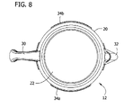
- FIG. 8 is a bottom plan view thereof
- FIG. 9 is a front elevation thereof
- FIG. 10 is a right side elevation thereof
- FIG. 11 is a rear elevation thereof
- FIG. 12 is a perspective view of the lid
- FIG. 13 is a top plan view thereof
- FIG. 14 is a bottom plan view thereof
- FIG. 15 is a front elevation thereof
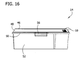
- FIG. 16 is a right side elevation thereof
- FIG. 17 is a left side elevation thereof
- FIG. 18 is a perspective view of the mixing device
- FIG. 19 is a top plan view thereof.
- FIG. 20 is a bottom plan view thereof
- FIG. 21 is a front elevation thereof
- FIG. 22 is a perspective view of the handle
- FIG. 23 is a top plan view thereof
- FIG. 24 is a bottom plan view thereof
- FIG. 25 is a front elevation thereof
- FIG. 26 is a perspective view of a shaft of the mixing device
- FIG. 27 is a top plan view thereof
- FIG. 28 is a bottom plan view thereof
- FIG. 29 is a side elevation thereof
- FIG. 30 is a top side perspective view of an agitating member of the mixing device.
- FIG. 31 is a bottom side perspective view thereof
- FIG. 32 is a top plan view thereof
- FIG. 33 is a bottom plan view thereof
- FIG. 34 is a side elevation thereof
- FIG. 35 is a perspective view of a stop of the mixing device
- FIG. 36 is a top plan view thereof
- FIG. 37 is a side elevation thereof
- FIG. 38 is a perspective view similar to FIG. 1 but with the lid in an unlocked position
- FIG. 39 is a section taken in the plane of line 39 - 39 of FIG. 1 ;
- FIG. 40 is an elevation of the agitating member connected to the shaft
- FIG. 41 is a top view thereof
- FIG. 42 is a section taken in the plane of line 42 - 42 of FIG. 41 ;
- FIGS. 43 and 44 are enlarged sections similar to FIG. 41 but showing the agitating member in the process of being disconnected from the shaft;
- FIG. 45 is an enlarged section similar to FIG. 44 but showing the agitating member disconnected from the shaft;
- FIG. 46 is an enlarged section similar to FIG. 45 but showing the agitating member in the process of being connected to the shaft;
- FIG. 47 is a side elevation of the handle connected to the shaft
- FIG. 48 is a top view thereof
- FIG. 49 is an enlarged section taken in the plane of line 49 - 49 of FIG. 48 ;
- FIG. 50 is a perspective view of a pitcher of a second embodiment wherein the container of the pitcher is transparent;
- FIG. 51 is a perspective view of a pitcher of a third embodiment
- FIG. 52 is an exploded perspective view thereof
- FIG. 53 is a perspective view of a container of the pitcher of FIG. 51 ;
- FIG. 54 is a perspective view of a lid of the pitcher
- FIG. 55 is a perspective view of a mixing device of the pitcher
- FIG. 56 is a perspective view of a shaft of the mixing device.
- FIG. 57 is a perspective view of a stop of the mixing device.
- the pitcher 10 generally comprises a container 12 for containing liquid, a lid 14 providing a closure for the container, and a mixing device 16 for mixing a liquid solution within the container.
- the container 12 , lid 14 , and mixing device 16 are indicated generally by their respective reference numbers in the accompanying figures.
- the mixing device 16 according to one particularly suitable embodiment is configured to mix liquid solution in the container 12 while minimizing the amount of air introduced into the solution during mixing.
- the pitcher 10 is suitable for mixing baby formula (e.g., mixing formula powder into water).
- baby formula e.g., mixing formula powder into water
- the pitcher may be used for other liquid-liquid or liquid-solid solutions without departing from the scope of this invention.
- the container 12 of the illustrated configuration has a generally cylindrical sidewall 20 (i.e., generally annular in cross-section) with a closed, flat bottom 22 and an open top 24 ( FIGS. 6-11 ).
- the sidewall 20 and bottom 22 of the container 12 cooperatively define an interior volume 26 adapted to receive and hold liquid as well as other materials, such as particulate matter, powder, or the like mixed with the liquid to form a liquid solution.
- the interior volume 26 of the illustrated container 12 is approximately thirty-two (32) ounces but it is understood that the container can be formed with a greater or smaller interior volume.
- Hash marks 28 a and indicia 28 b are provided on an outer surface of the sidewall 20 for allowing easy measurement of liquid placed in the container 12 .
- the hash marks 28 a and indicia 28 b are spaced appropriately so that approximately four (4) ounces of liquid can be held by the container 12 between adjacent hash marks. For example, from the bottom 22 of the container 12 to the first hash mark is four (4) ounces, from the bottom to the second hash mark is eight (8) ounces and so on.
- the sidewall 20 can be free of hash marks and/or indicia and that the distance between hash marks and/or indicia can be different or correspond to other known units of measuring liquids besides ounces (e.g., milliliters, liters, cups).
- hash marks and/or indicia can be placed on the outer surface of the sidewall 20 to represent more than one unit of measurement.
- hash marks and/or indicia can be provided for ounces, milliliters, liters, and cups.
- the illustrated container 12 is translucent but it is contemplated that the container may be transparent (as shown in the alternative embodiment of FIG. 50 ) or opaque.
- the container 12 includes a handle 30 attached to the sidewall 20 and a spout 32 for pouring liquid solution from the container.
- the handle 30 allows a user to easily pick up and tilt the container 12 thereby allowing solution to flow out of the pitcher 10 at the spout 32 .
- the handle 30 is formed separate from the sidewall 20 and secured thereto (e.g., such as by adhesive or other securement techniques) but it is understood that the handle and the sidewall can be formed as one piece.
- the spout 32 of the illustrated configuration is relatively small to assist in pouring liquid solution into receptacles with relatively small openings (e.g., the mouth of a baby bottle) and includes a purchase rib 32 a to prevent the spout 32 from slipping out of the receptacle being filled. But it is understood that the spout 32 can have different sizes and configurations.
- the handle 30 is located on the side of the container 12 opposite the spout 32 . While this configuration is preferred, it is contemplated that the handle 30 and spout 32 can have different locations relative to each other within the scope of this invention.
- the container 12 also has two circumferentially extending rails 34 a , 34 b . These rails 34 a , 34 b are located on opposite sides of the sidewall 20 to extend generally between the handle 30 and the spout 32 adjacent to the open top 24 .
- the lid 14 has a pair of tabs 56 extending radially therefrom and being generally C-shaped in cross-section to define a channel 58 sized for receiving the rails 34 a , 34 b therein to lock the lid on the container 12 .
- the lid 14 includes a generally circular top portion 40 and a depending sidewall 52 from which the tabs 56 extend.
- a recess 42 is formed centrally in the top of the lid and includes a generally circular portion 42 a and two, opposed frustum portions 42 b .
- An opening 43 is formed in the top of the lid, at the bottom of the recess 42 , with a central opening 43 a and a pair of key slots 43 b extending radially outward from opposite sides of the central opening 43 a .
- the lid 14 Adjacent the circumferential edge of the top 40 , the lid 14 is formed to have an upward ramp 44 , a narrow plateau 46 , and a downward ramp 48 , respectively.
- An annular ring 50 extends about the edge of the downward ramp 48 .
- the sidewall 52 depends from the downward ramp 48 .
- a generally U-shaped cutout 54 is formed in the sidewall 52 for alignment with the spout 32 to allow liquid to pass through the lid 14 to the spout.
- Indicia 59 is located on the downward ramp 48 to identify the location of the cutout 54 .
- the word “open” is located above the cutout 54 while the word “closed” is disposed on both sides of the word “open” and spaced from the cutout. It is understood that the lid 14 can have a configuration different than illustrated herein.
- the mixing device 16 generally comprises a grip 60 , a shaft 80 , a stop 120 located on the shaft, and an agitating member 100 operatively connected to the shaft.
- the grip 60 which is shown in detail in FIGS. 22-25 , is generally T-shaped having a gripping portion 62 and a connecting portion 64 .
- the gripping portion 62 is adapted to be gripped by the user during mixing of the liquids within the container 12 .
- the gripping portion 62 is curved with a smooth, arcuate upper surface for engagement by the user's palm, and an undulating bottom surface for engagement by the user's fingers.
- the gripping portion 62 tapers as it extends from its center toward its ends.
- the connecting portion 64 of the grip 60 includes a generally cylindrical sidewall 66 and a flat bottom 68 .
- the sidewall 66 and bottom 68 cooperatively define a cavity 72 .
- a slot 70 extends through the sidewall 66 and bottom 68 to provide access to the cavity 72 .
- the slot 70 extending through the sidewall 66 has a greater width at a location spaced from the bottom 68 of the connecting portion 64 than a width of the slot adjacent the bottom.
- Two frustum extensions 74 a , 74 b are spaced from the slot 70 and disposed on opposite sides of the sidewall 66 from each other.
- the shaft 80 is elongate, having a first end releasably connectable to the grip 60 and a second end opposite the first end and releasably connectable to the agitating member 100 .
- a pair of opposed fins 84 a , 84 b spiral helically around the shaft 80 intermediate the ends of the shaft.
- each of the fins 84 a , 84 b extends around the shaft 80 twice but it is understood that the fins can extend around the shaft more or fewer times depending on the desired rotation of the agitating member 100 .
- Spaced apart annular grooves 86 are provided along the length of the shaft 80 .
- the first end of the shaft 80 is formed to have a neck 88 and an enlarged head 90 above the neck.
- the second end of the shaft 80 includes a generally elliptical flange 92 and a pair of resilient fingers 94 a , 94 b depending from the flange.
- the flange 92 includes generally straight longitudinal edges and arcuate lateral edges therebetween.
- Each of the fingers 94 a , 94 b are located inward of a respective arcuate lateral edge and include a circumferential ridge 96 spaced from the flange 92 .
- Each ridge 96 includes an upper tapered surface 98 a and a lower tapered surface 98 b to generally define a latch for releasably connecting the shaft 80 to the agitating member 100 .
- the upper tapered surface 98 a has a slope substantially greater than the slope of the lower tapered surface 98 b.
- the agitating member 100 of the mixing device 16 includes a cylindrical hub 102 having ends, a plurality of blades 104 extending outward from the hub, and an annular support 106 spaced from the hub and interconnecting each of the blades.
- the hub 102 which is tubular, has a passage 108 therein.
- An annular catch 112 extends about the interior of the hub 102 into the passage 108 at a location between the ends of the hub ( FIG. 31 ).
- one end of the hub is sized and shaped for receiving the flange 92 of the shaft 80 .
- the end of the hub 102 includes a socket 110 having two generally straight edges and arcuate edges extending between and interconnecting the straight edges.
- the agitating member 100 has seven blades 104 but it is understood that more or fewer blades can be used.
- Each of the blades 104 is disposed at an angle with respect to the hub 102 and annular support 106 . Since each of the blades 104 is also curved along its length, the angle of the blade at the location where the blade contacts the hub 102 is substantially different than the angle of the blade at the location where the blade contacts the annular support 106 . It is understood that the blades 104 can have different configurations and orientation than those illustrated herein.
- the annular support 106 is connected to the outer edges of each of the blades 104 but it is understood that the annular support could be located closer to the hub 102 . It is also contemplated that the annular support 106 can interconnect fewer blades 104 . For example, the annular support 106 can be configured to interconnect every other blade 104 or every third blade. It is further contemplated that the annular support 106 could be omitted without departing from the scope of this invention.
- the agitating member 100 of the illustrated configuration is formed as a single piece. That is, the hub 102 , blades 104 , and annular support 106 are formed as one piece, e.g., by molding. It is understood, though, that the agitating member 100 may be formed from two or more pieces and assembled together.
- the stop 120 has a central opening 122 formed therein along with a pair of key slots extending radially from opposite sides of the opening.
- the central opening is sized to accommodate the shaft 80 therethrough with the fins 84 a , 84 b of the shaft disposed in the key slots.
- Opposed engagement ribs 126 are located on the inner wall of the stop 120 at the central opening 122 to extend inward of the opening.
- the ribs 126 are configured for seating in the respective grooves 86 in the shaft 80 to releasably secure the stop at a desired location along the shaft.
- the stop 120 can thus be selectively moved along the shaft 80 and secured in place by aligning the engagement ribs 126 with one of the grooves 86 in the shaft so that the engagement ribs are received in the groove. It is understood that the stop 120 can have different configurations.
- the user fills the container 12 with the desired amount of water (or other liquid) and adds powered formula (or other material to be mixed) into the container.
- the user assembles the mixing device 16 by connecting the agitating member 100 , stop 120 , and grip 60 to the shaft 80 .
- the agitating member 100 is connected to the shaft 80 by inserting the fingers 94 a , 94 b of the shaft into the passage 108 of the hub 102 of the agitating member. See FIGS. 40-46 .
- the fingers 94 a , 94 b are pushed into the passage 108 , the lower tapered surfaces 98 b of the ridges 96 of the fingers engage ( FIG.
- the fingers 94 a , 94 b are thereby bent toward each other which allows the ridges 96 of the fingers to pass the catch 112 , as shown in FIG. 44 .
- the fingers 94 a , 94 b spring back to approximately their initial configuration thereby allowing the ridges 96 on the fingers and the catch 112 on the hub 102 to cooperatively secure the agitating member 100 to the shaft 80 ( FIG. 43 ) for conjoint translation with the shaft relative to the container 12 .
- the generally elliptical flange 92 of the shaft 80 is received in the socket 110 of the hub 102 to operatively connect the agitating member 100 to the shaft for conjoint rotation therewith relative to the container 12 . It is understood, however, that the agitating member 110 and shaft 80 may be instead permanently connected to each other or releasably connected to each other in ways different than those disclosed herein without departing from the scope of this invention.
- the stop 120 is suitably located on the shaft 80 at a groove 86 location that corresponds to the level of liquid in the container or less. As a result, upon translation the stop 120 prevents the agitating member 100 from being pulled above the water line WL ( FIG. 4 ).
- the shaft 80 is inserted through the opening 43 in the lid 14 so that the fins 84 a , 84 b of the shaft are received in the respective key slots 43 b of the opening 43 in the lid and the shaft 80 is received in the central portion 43 a of the opening.
- the grip 60 is releasably connected to the shaft 80 by inserting the head 90 and neck 88 of the shaft transversely through the slot 70 in the grip.
- the head 90 aligns with the wider portion of the slot 70 and the neck 88 aligns with the narrow portion.
- the head 90 is received in the cavity 72 in the grip 60 , which connects the grip to the shaft ( FIGS. 47-49 ). This connection allows the shaft 80 to rotate independently of the grip 60 while allowing the shaft to translate (i.e., move up and down) with the grip.
- grip 60 and shaft 80 can be permanently connected to each other or releasably connected to each other in ways different than those disclosed herein without departing from the scope of this invention.
- the lid 14 is placed on the container 12 by aligning the tabs 56 circumferentially away from the rails 34 a , 34 b of the container ( FIG. 38 ) and then rotating the lid in clockwise direction so that the rails are received in the channels 58 of the tabs ( FIG. 39 ) to lock the lid on the container.
- the lid 14 is placed on the container 12 so that the sidewall 52 of the lid is received in the interior volume 26 of the container against the sidewall of the container adjacent the top of the container.
- the rails 34 a , 34 b of the container 12 receiving the channels 58 in the tabs 56 of the lid 14 , the lid is fixed against removal from the container. However, the lid 14 is still rotatable while on the container 12 to open and close access to the spout 32 . It is understood that the lid 14 may be releasably secured to the container 12 in different ways.
- the user grasps the grip 60 and cyclically pulls it upward (i.e., away from the lid 14 ) and pushes it downward (i.e., toward the lid).
- This motion conjointly translates the shaft 80 and hence the agitating member 100 up and down within the liquid solution to be mixed.
- the shaft 80 is caused to rotate, thereby rotating the agitating member 100 in the liquid solution.
- the combined translation and rotation of the agitating member 100 acts to thoroughly mix the liquid solution in the container 12 .
- the grip 60 via its connection to the shaft 80 does not rotate.
- the stop 120 contacts the underside of the lid 14 (and more particularly the connecting member) to prevent any further upward motion of the grip 60 .
- the lid 14 can be rotated from its closed position to its opened position wherein the cutout 54 in the lid is aligned with the spout 32 so that the formula can be poured into, for example, a baby bottle (not shown). Any formula remaining in the container 12 can be stored therein by rotating the lid 14 back to its closed position.
- the grip 60 may be placed in a stowed position on the lid by inserting the frustum extensions 74 a , 74 b of the grip into the two frustum portions 42 b of the recess 42 formed in the lid 14 .
- the grip 60 can be used to rotate the lid 14 with respect to the container 12 to the various positions of the lid (e.g., open, closed, locked, unlocked).
- the remaining formula can be remixed at any time by moving the grip 60 from its stowed position ( FIGS. 1 , 2 , and 39 ) to its operative position ( FIGS. 3 and 4 ) and moving it up and down as described above.
- the pitcher 10 can be disassembled and washed such as by running the components of the pitcher through a dishwasher.
- the force necessary to disconnect the agitating member 100 from the shaft 80 is suitably substantially greater then the force necessary to connect the agitating member with the shaft as a result of the differences in slope between the upper and lower tapered surfaces 98 a , 98 b of the ridges 96 of the fingers 94 a , 94 b .
- the components of the illustrated pitcher 10 are formed from suitable plastic but it is understood that other suitable materials may be used.
- FIGS. 51-57 illustrate a pitcher 200 of a third embodiment that is similar to the pitchers 10 , 10 ′ of the first and second embodiments.
- a lid 214 of the third embodiment has a pair of tabs 256 extending radially therefrom and being generally C-shaped in cross-section to define a channel 258 sized for receiving rails 234 a , 234 b disposed on the container 212 to lock the lid on the container ( FIG. 54 ).
- Each of the tabs 256 of the lid 214 of the third embodiment of the pitcher 200 include ridges 256 a formed thereon to provide finger grips to facilitate manual rotation of the lid 214 between various positions of the lid (e.g., open, closed, locked, unlocked). It is understood that the finger grips could be formed differently (e.g., bumps or grooves).
- a circular recess 242 is formed centrally in a top portion 240 of the lid 214 but it does not include frustum portions such as the two, opposed frustum portions 42 b seen in FIG. 12 .
- two generally U-shaped cutouts 254 are formed in a sidewall 252 of the lid 214 instead of just one.
- the lid 214 can be rotated 180 degrees and still be used to pour liquid from the container 212 through one of the two cutouts 254 .
- the lid 214 has two open (i.e., pouring) positions instead of one as illustrated in the prior embodiments.
- Suitable indicia 259 is located on the lid 214 to identify the various positions of the lid with respect to the container 212 , e.g., a spout 232 of the container.
- the word “open” is located above both of the cutouts 154 while the word “closed/mix” is disposed on both sides of the word “open” and spaced from the cutouts.
- a mixing device 216 of this embodiment comprises a grip 260 , a shaft 280 , a stop 320 located on the shaft, and an agitating member 300 operatively connected to the shaft.
- the grip 260 is generally T-shaped having a gripping portion 262 adapted to be gripped by the user during mixing of the liquids within the container 212 and a connecting portion 264 adapted to connect the grip to the shaft 280 .
- the grip 260 is similar to the grip 60 illustrated in FIGS. 22-25 except the grip of the third embodiment of the pitcher 200 does not include two frustum extensions (e.g., frustum extensions 74 a , 74 b of FIG. 25 ). As a result, the grip 260 is configured for being partially received in the circular recess 242 formed in the top portion 240 of the lid 214 .
- the shaft 280 is elongate, having a first end releasably connectable to the grip 260 and a second end opposite the first end and releasably connectable to the agitating member 300 .
- the shaft 280 is substantially similar to the shaft 80 illustrated in FIGS. 26-29 except that a generally elliptical flange 292 disposed near the second end of the shaft 280 includes two cutouts formed in the flange.
- the agitating member 300 of the mixing device 216 of FIG. 55 is substantially the same as the agitating member 100 of FIGS. 30-34 and therefore attaches to the shaft 280 in the same manner as previously described and illustrated. As a result of the cutouts formed in the flange 292 , however, a passageway is formed through the connection of the shaft 280 and the agitating member 300 .
- the passageway allows liquid and any particulate therein to flow therethrough during the mixing process to increase the mixing capabilities of the mixing device 216 and to reduce the buildup of particulates beneath the flange.
- the stop 320 of the mixing device 216 has a central opening 322 formed therein that is sized to accommodate the shaft 280 .
- the stop 120 of this embodiment includes cutouts on opposite sides of the stop that generally correspond to and axially align with the cutouts in the flange 292 when the stop is at its lowest point on the shaft 280 .
- the stop 120 allows liquid and particulates to flow through the passageway in the connection of the shaft 280 and the agitating member 300 without impedance by the stop.
Landscapes
- Chemical & Material Sciences (AREA)
- Chemical Kinetics & Catalysis (AREA)
- Engineering & Computer Science (AREA)
- Mechanical Engineering (AREA)
- Food Science & Technology (AREA)
- Mixers Of The Rotary Stirring Type (AREA)
Abstract
Description
Claims (25)
Priority Applications (2)
| Application Number | Priority Date | Filing Date | Title |
|---|---|---|---|
| US11/852,066 US8534908B2 (en) | 2007-04-20 | 2007-09-07 | Pitcher having mixing device |
| PCT/US2008/060087 WO2008130875A1 (en) | 2007-04-20 | 2008-04-11 | Pitcher having mixing device |
Applications Claiming Priority (2)
| Application Number | Priority Date | Filing Date | Title |
|---|---|---|---|
| US91307307P | 2007-04-20 | 2007-04-20 | |
| US11/852,066 US8534908B2 (en) | 2007-04-20 | 2007-09-07 | Pitcher having mixing device |
Publications (2)
| Publication Number | Publication Date |
|---|---|
| US20080259723A1 US20080259723A1 (en) | 2008-10-23 |
| US8534908B2 true US8534908B2 (en) | 2013-09-17 |
Family
ID=39872037
Family Applications (1)
| Application Number | Title | Priority Date | Filing Date |
|---|---|---|---|
| US11/852,066 Active 2031-07-21 US8534908B2 (en) | 2007-04-20 | 2007-09-07 | Pitcher having mixing device |
Country Status (2)
| Country | Link |
|---|---|
| US (1) | US8534908B2 (en) |
| WO (1) | WO2008130875A1 (en) |
Cited By (10)
| Publication number | Priority date | Publication date | Assignee | Title |
|---|---|---|---|---|
| US20120043406A1 (en) * | 2009-04-03 | 2012-02-23 | Leifheit Ag | Drive device for driving a work unit |
| US9346602B2 (en) | 2014-01-20 | 2016-05-24 | Joshua Gitta | Cocktail glass |
| USD763042S1 (en) * | 2015-02-13 | 2016-08-09 | Whirlpool Corporation | Coffee press |
| WO2016179107A1 (en) * | 2015-05-01 | 2016-11-10 | Sunbeam Products, Inc. | Blending appliance with suction blade |
| US20160346746A1 (en) * | 2015-05-27 | 2016-12-01 | Titan Mixer Bottle, Llc | Apparatus, device, and methods for mixing substances |
| US20180093236A1 (en) * | 2016-09-30 | 2018-04-05 | Munchkin, Inc. | Mixing container |
| USD825245S1 (en) | 2016-08-24 | 2018-08-14 | Whirlpool Corporation | Brewer |
| US10099187B2 (en) | 2015-09-08 | 2018-10-16 | Adip Management, Llc | Mixing systems and methods |
| US10213053B2 (en) | 2015-09-08 | 2019-02-26 | Adip Management, Llc | Whisk mixing systems within a container |
| US20220396397A1 (en) * | 2021-06-15 | 2022-12-15 | Robert F. Wallace, Jr. | Mixing bottle and method therefor |
Families Citing this family (15)
| Publication number | Priority date | Publication date | Assignee | Title |
|---|---|---|---|---|
| DE102008030623A1 (en) * | 2008-01-03 | 2009-07-09 | Umsonst-Kübler, Petra | Device for mixing a mass |
| CH702957A1 (en) * | 2010-04-08 | 2011-10-14 | Pi Design Ag | Beverage maker with blockable actuating rod. |
| US9643141B2 (en) * | 2011-10-27 | 2017-05-09 | Trimr, Llc | Shakeable container with agitator |
| EP2906097A4 (en) * | 2012-10-10 | 2016-06-08 | Umoro Inc | Shaker bottle |
| USD804247S1 (en) | 2012-10-26 | 2017-12-05 | Trimr, Llc | Agitator on straw or rod for a shakable container |
| DE102013017310B4 (en) * | 2013-07-02 | 2018-03-01 | Florian Enghard | Mixing bowl |
| US20150216361A1 (en) * | 2014-01-31 | 2015-08-06 | Vim & Vigor Design Inc. | Device and method for mixing drinks |
| US9637289B1 (en) * | 2014-06-06 | 2017-05-02 | Galomb, Inc. | Package closure with rotatable material stripping element |
| US10244772B2 (en) * | 2014-11-06 | 2019-04-02 | Sagra, Inc. | Method for creating layered chocolate body and chocolate mold for creation thereof |
| US20160192810A1 (en) * | 2015-01-06 | 2016-07-07 | Jeff Andrew Knapp | Free floating mixing blade |
| AU365020S (en) * | 2015-05-27 | 2015-11-03 | Breville R & D Pty Ltd | Jug |
| CN105597605B (en) * | 2016-02-22 | 2018-06-22 | 宁夏朗盛精密制造技术有限公司 | Anti- precipitation agitator |
| US11045028B1 (en) * | 2018-01-15 | 2021-06-29 | Jason Lenhardt | Drinking straw with agitator |
| WO2021034965A1 (en) * | 2019-08-20 | 2021-02-25 | Craig Scott E | Apparatus and method for extracting essential oils |
| GB201915237D0 (en) | 2019-10-22 | 2019-12-04 | Vsl Ltd | Improved drinks bottle |
Citations (59)
| Publication number | Priority date | Publication date | Assignee | Title |
|---|---|---|---|---|
| US66306A (en) * | 1867-07-02 | Peters | ||
| US77431A (en) * | 1868-04-28 | Charles h | ||
| US400547A (en) * | 1889-04-02 | Charles baker crafton | ||
| US426525A (en) * | 1890-04-29 | Churn | ||
| US467627A (en) * | 1892-01-26 | Nut-lock | ||
| US505692A (en) * | 1893-09-26 | Drink-mixer | ||
| US597077A (en) * | 1898-01-11 | Eduard ackermann | ||
| US681386A (en) * | 1900-09-10 | 1901-08-27 | Gomer G Beynon | Churn. |
| US817310A (en) * | 1905-07-28 | 1906-04-10 | James L Forbes | Churn. |
| US1068450A (en) * | 1912-06-22 | 1913-07-29 | Dorsey Mfg Company | Beater and mixer. |
| US1133413A (en) * | 1914-03-16 | 1915-03-30 | Turney H Stough | Kitchen utensil. |
| US1165307A (en) * | 1913-09-11 | 1915-12-21 | Edward D Farmer | Culinary beater. |
| US1237585A (en) * | 1915-11-20 | 1917-08-21 | Paul Tripke | Combined egg-separator and beating device. |
| US1238461A (en) * | 1915-11-20 | 1917-08-28 | Paul Tripke | Combined egg-separator and juice-extractor, and beating device. |
| US1282148A (en) * | 1915-12-20 | 1918-10-22 | Paul Tripke | Combined egg separator and beater. |
| US1373761A (en) * | 1920-02-03 | 1921-04-05 | Rabin Samuel | Beater and mixer |
| US1413874A (en) * | 1921-08-11 | 1922-04-25 | Harris Company Inc | Egg beater |
| US1415334A (en) * | 1918-09-23 | 1922-05-09 | Marshall D Gibson | Churn |
| US1798757A (en) * | 1927-12-03 | 1931-03-31 | James A Willey | Egg beater and mixer |
| US1918117A (en) * | 1931-07-06 | 1933-07-11 | Corning Glass Works | Method of and means for preventing aqueous liquids from dripping from the lips of vessels |
| US1948431A (en) * | 1932-07-26 | 1934-02-20 | Rolph William Mair | Mixing device |
| US1987700A (en) * | 1933-08-11 | 1935-01-15 | Herbert H Muir | Egg beater mechanism |
| US2059910A (en) * | 1935-12-26 | 1936-11-03 | Abbott Lab | Bottle finish |
| US2158912A (en) * | 1939-01-10 | 1939-05-16 | Anthony J Piperi | Beater |
| US2162348A (en) * | 1938-10-21 | 1939-06-13 | Na Mac Products Company | Liquid dispenser and mixer |
| US2181833A (en) * | 1938-07-01 | 1939-11-28 | Marie Milano | Beater or mixer |
| US2266186A (en) * | 1940-11-29 | 1941-12-16 | Fischer Charles | Mixing utensil |
| US2559196A (en) * | 1950-07-12 | 1951-07-03 | Nicholas J Medved | Time saver frying pan lid |
| US2587344A (en) * | 1945-11-14 | 1952-02-26 | Livingstone Jay Gould | Nondrip pouring outlet |
| US2726071A (en) * | 1952-11-14 | 1955-12-06 | Bernhardt Rudolph | Mixer and aerator |
| US2740617A (en) * | 1953-02-03 | 1956-04-03 | Howard L Ball | Stirring spoon |
| US2749098A (en) * | 1955-07-21 | 1956-06-05 | Albert H Johnson | Mixer |
| US2788830A (en) * | 1953-06-08 | 1957-04-16 | Rosan Joseph | Threaded mounting device having split ring installation stop means retained thereon |
| US2922628A (en) * | 1957-03-11 | 1960-01-26 | Emil Koe Jr | Mixing device |
| US3009686A (en) * | 1960-04-29 | 1961-11-21 | Kaplan Nathan | Mixing device |
| US3114484A (en) * | 1960-09-14 | 1963-12-17 | Youngstown Steel Door Co | Pouring top assembly for fluid containers |
| US3115664A (en) * | 1961-03-23 | 1963-12-31 | Re Giovanni | Mixing-stirring cap for nail polish bottles and the like |
| US3154123A (en) * | 1963-04-02 | 1964-10-27 | Barnard E Tomlinson | Frozen material shaving and mixing apparatus |
| US3417971A (en) * | 1967-02-23 | 1968-12-24 | Robert J. Blank | Mixing and ejection tool |
| US3619081A (en) * | 1969-12-04 | 1971-11-09 | American Home Prod | Beater for comestibles and the like |
| US3738535A (en) * | 1970-10-26 | 1973-06-12 | A Nicholls | Mixing and proportioning syringe |
| US3744767A (en) * | 1972-04-17 | 1973-07-10 | W Blasnik | Rotary mixer |
| US4359283A (en) | 1981-04-29 | 1982-11-16 | Sperry Corporation | Juice container and stirrer |
| US4946286A (en) * | 1988-11-23 | 1990-08-07 | The Coca-Cola Company | Liquid pitcher including a mixing and grinding mechanism |
| US5199788A (en) * | 1990-02-12 | 1993-04-06 | Dorothy Stallings | Apparatus for sealing a liquid container |
| US5284389A (en) * | 1993-06-01 | 1994-02-08 | Lumsden Karen J | Juice concentrate mixing and dispensing apparatus |
| USD384237S (en) | 1996-02-15 | 1997-09-30 | The Pampered Chef, Ltd. | Juice pitcher |
| US5695282A (en) | 1996-02-23 | 1997-12-09 | The Pampered Chef, Ltd. | Mixing pitcher |
| USD426742S (en) | 1999-02-26 | 2000-06-20 | The Pampered Chef, Ltd. | Mixing container |
| US6095676A (en) | 1998-12-30 | 2000-08-01 | Kuan; Huo Feng Hsia | Dairy product whipping apparatus |
| US6200015B1 (en) | 1999-02-26 | 2001-03-13 | The Pampered Chef, Ltd. | Mixing container |
| US6227419B1 (en) | 1999-08-18 | 2001-05-08 | Chilton Industries | Spout |
| US6231226B1 (en) | 2000-02-29 | 2001-05-15 | The Pampered Chef, Ltd. | Mixing Pitcher |
| USD453089S1 (en) | 2000-02-29 | 2002-01-29 | The Pampered Chef, Ltd. | Mixing pitcher |
| US6367962B1 (en) * | 1998-12-21 | 2002-04-09 | Ngk Spark Plug Co., Ltd. | Device and method for preparing calcium phosphate-based bone cement |
| US6431743B1 (en) * | 1999-10-06 | 2002-08-13 | Ngk Spark Plug Co., Ltd. | Method of preparing and extruding a chemical agent using a kneader and chemical-agent extrusion assisting tool |
| US6895672B2 (en) * | 2003-08-15 | 2005-05-24 | Terry J. Conforti | Kitchen utensil |
| US20070291585A1 (en) * | 2006-06-14 | 2007-12-20 | Dave Sivers | Liquid container with stir mechanism |
| US20090238030A1 (en) * | 2008-03-19 | 2009-09-24 | Harry Hensler | Whisk |
-
2007
- 2007-09-07 US US11/852,066 patent/US8534908B2/en active Active
-
2008
- 2008-04-11 WO PCT/US2008/060087 patent/WO2008130875A1/en active Application Filing
Patent Citations (59)
| Publication number | Priority date | Publication date | Assignee | Title |
|---|---|---|---|---|
| US597077A (en) * | 1898-01-11 | Eduard ackermann | ||
| US66306A (en) * | 1867-07-02 | Peters | ||
| US400547A (en) * | 1889-04-02 | Charles baker crafton | ||
| US426525A (en) * | 1890-04-29 | Churn | ||
| US467627A (en) * | 1892-01-26 | Nut-lock | ||
| US505692A (en) * | 1893-09-26 | Drink-mixer | ||
| US77431A (en) * | 1868-04-28 | Charles h | ||
| US681386A (en) * | 1900-09-10 | 1901-08-27 | Gomer G Beynon | Churn. |
| US817310A (en) * | 1905-07-28 | 1906-04-10 | James L Forbes | Churn. |
| US1068450A (en) * | 1912-06-22 | 1913-07-29 | Dorsey Mfg Company | Beater and mixer. |
| US1165307A (en) * | 1913-09-11 | 1915-12-21 | Edward D Farmer | Culinary beater. |
| US1133413A (en) * | 1914-03-16 | 1915-03-30 | Turney H Stough | Kitchen utensil. |
| US1237585A (en) * | 1915-11-20 | 1917-08-21 | Paul Tripke | Combined egg-separator and beating device. |
| US1238461A (en) * | 1915-11-20 | 1917-08-28 | Paul Tripke | Combined egg-separator and juice-extractor, and beating device. |
| US1282148A (en) * | 1915-12-20 | 1918-10-22 | Paul Tripke | Combined egg separator and beater. |
| US1415334A (en) * | 1918-09-23 | 1922-05-09 | Marshall D Gibson | Churn |
| US1373761A (en) * | 1920-02-03 | 1921-04-05 | Rabin Samuel | Beater and mixer |
| US1413874A (en) * | 1921-08-11 | 1922-04-25 | Harris Company Inc | Egg beater |
| US1798757A (en) * | 1927-12-03 | 1931-03-31 | James A Willey | Egg beater and mixer |
| US1918117A (en) * | 1931-07-06 | 1933-07-11 | Corning Glass Works | Method of and means for preventing aqueous liquids from dripping from the lips of vessels |
| US1948431A (en) * | 1932-07-26 | 1934-02-20 | Rolph William Mair | Mixing device |
| US1987700A (en) * | 1933-08-11 | 1935-01-15 | Herbert H Muir | Egg beater mechanism |
| US2059910A (en) * | 1935-12-26 | 1936-11-03 | Abbott Lab | Bottle finish |
| US2181833A (en) * | 1938-07-01 | 1939-11-28 | Marie Milano | Beater or mixer |
| US2162348A (en) * | 1938-10-21 | 1939-06-13 | Na Mac Products Company | Liquid dispenser and mixer |
| US2158912A (en) * | 1939-01-10 | 1939-05-16 | Anthony J Piperi | Beater |
| US2266186A (en) * | 1940-11-29 | 1941-12-16 | Fischer Charles | Mixing utensil |
| US2587344A (en) * | 1945-11-14 | 1952-02-26 | Livingstone Jay Gould | Nondrip pouring outlet |
| US2559196A (en) * | 1950-07-12 | 1951-07-03 | Nicholas J Medved | Time saver frying pan lid |
| US2726071A (en) * | 1952-11-14 | 1955-12-06 | Bernhardt Rudolph | Mixer and aerator |
| US2740617A (en) * | 1953-02-03 | 1956-04-03 | Howard L Ball | Stirring spoon |
| US2788830A (en) * | 1953-06-08 | 1957-04-16 | Rosan Joseph | Threaded mounting device having split ring installation stop means retained thereon |
| US2749098A (en) * | 1955-07-21 | 1956-06-05 | Albert H Johnson | Mixer |
| US2922628A (en) * | 1957-03-11 | 1960-01-26 | Emil Koe Jr | Mixing device |
| US3009686A (en) * | 1960-04-29 | 1961-11-21 | Kaplan Nathan | Mixing device |
| US3114484A (en) * | 1960-09-14 | 1963-12-17 | Youngstown Steel Door Co | Pouring top assembly for fluid containers |
| US3115664A (en) * | 1961-03-23 | 1963-12-31 | Re Giovanni | Mixing-stirring cap for nail polish bottles and the like |
| US3154123A (en) * | 1963-04-02 | 1964-10-27 | Barnard E Tomlinson | Frozen material shaving and mixing apparatus |
| US3417971A (en) * | 1967-02-23 | 1968-12-24 | Robert J. Blank | Mixing and ejection tool |
| US3619081A (en) * | 1969-12-04 | 1971-11-09 | American Home Prod | Beater for comestibles and the like |
| US3738535A (en) * | 1970-10-26 | 1973-06-12 | A Nicholls | Mixing and proportioning syringe |
| US3744767A (en) * | 1972-04-17 | 1973-07-10 | W Blasnik | Rotary mixer |
| US4359283A (en) | 1981-04-29 | 1982-11-16 | Sperry Corporation | Juice container and stirrer |
| US4946286A (en) * | 1988-11-23 | 1990-08-07 | The Coca-Cola Company | Liquid pitcher including a mixing and grinding mechanism |
| US5199788A (en) * | 1990-02-12 | 1993-04-06 | Dorothy Stallings | Apparatus for sealing a liquid container |
| US5284389A (en) * | 1993-06-01 | 1994-02-08 | Lumsden Karen J | Juice concentrate mixing and dispensing apparatus |
| USD384237S (en) | 1996-02-15 | 1997-09-30 | The Pampered Chef, Ltd. | Juice pitcher |
| US5695282A (en) | 1996-02-23 | 1997-12-09 | The Pampered Chef, Ltd. | Mixing pitcher |
| US6367962B1 (en) * | 1998-12-21 | 2002-04-09 | Ngk Spark Plug Co., Ltd. | Device and method for preparing calcium phosphate-based bone cement |
| US6095676A (en) | 1998-12-30 | 2000-08-01 | Kuan; Huo Feng Hsia | Dairy product whipping apparatus |
| US6200015B1 (en) | 1999-02-26 | 2001-03-13 | The Pampered Chef, Ltd. | Mixing container |
| USD426742S (en) | 1999-02-26 | 2000-06-20 | The Pampered Chef, Ltd. | Mixing container |
| US6227419B1 (en) | 1999-08-18 | 2001-05-08 | Chilton Industries | Spout |
| US6431743B1 (en) * | 1999-10-06 | 2002-08-13 | Ngk Spark Plug Co., Ltd. | Method of preparing and extruding a chemical agent using a kneader and chemical-agent extrusion assisting tool |
| US6231226B1 (en) | 2000-02-29 | 2001-05-15 | The Pampered Chef, Ltd. | Mixing Pitcher |
| USD453089S1 (en) | 2000-02-29 | 2002-01-29 | The Pampered Chef, Ltd. | Mixing pitcher |
| US6895672B2 (en) * | 2003-08-15 | 2005-05-24 | Terry J. Conforti | Kitchen utensil |
| US20070291585A1 (en) * | 2006-06-14 | 2007-12-20 | Dave Sivers | Liquid container with stir mechanism |
| US20090238030A1 (en) * | 2008-03-19 | 2009-09-24 | Harry Hensler | Whisk |
Non-Patent Citations (1)
| Title |
|---|
| International Search Report for PCT/US2008/060087, dated Aug. 11, 2008, 8 pages. |
Cited By (15)
| Publication number | Priority date | Publication date | Assignee | Title |
|---|---|---|---|---|
| US20120043406A1 (en) * | 2009-04-03 | 2012-02-23 | Leifheit Ag | Drive device for driving a work unit |
| US9346602B2 (en) | 2014-01-20 | 2016-05-24 | Joshua Gitta | Cocktail glass |
| USD763042S1 (en) * | 2015-02-13 | 2016-08-09 | Whirlpool Corporation | Coffee press |
| US20180110374A1 (en) * | 2015-05-01 | 2018-04-26 | Sunbeam Products, Inc. | Blending appliance with suction blade |
| WO2016179107A1 (en) * | 2015-05-01 | 2016-11-10 | Sunbeam Products, Inc. | Blending appliance with suction blade |
| US20160346746A1 (en) * | 2015-05-27 | 2016-12-01 | Titan Mixer Bottle, Llc | Apparatus, device, and methods for mixing substances |
| US10104994B2 (en) * | 2015-05-27 | 2018-10-23 | Titan Mixer Bottle, Llc | Apparatus, device, and methods for mixing substances |
| US10327573B2 (en) * | 2015-05-27 | 2019-06-25 | Titan Mixer Bottle, Llc | Apparatus, device, and methods for mixing substances |
| US10099187B2 (en) | 2015-09-08 | 2018-10-16 | Adip Management, Llc | Mixing systems and methods |
| US10213053B2 (en) | 2015-09-08 | 2019-02-26 | Adip Management, Llc | Whisk mixing systems within a container |
| USD825245S1 (en) | 2016-08-24 | 2018-08-14 | Whirlpool Corporation | Brewer |
| US20180093236A1 (en) * | 2016-09-30 | 2018-04-05 | Munchkin, Inc. | Mixing container |
| US10363527B2 (en) * | 2016-09-30 | 2019-07-30 | Munchkin, Inc. | Mixing container |
| US20220396397A1 (en) * | 2021-06-15 | 2022-12-15 | Robert F. Wallace, Jr. | Mixing bottle and method therefor |
| US12017819B2 (en) * | 2021-06-15 | 2024-06-25 | Robert F. Wallace, Jr. | Mixing bottle and method therefor |
Also Published As
| Publication number | Publication date |
|---|---|
| WO2008130875A1 (en) | 2008-10-30 |
| US20080259723A1 (en) | 2008-10-23 |
Similar Documents
| Publication | Publication Date | Title |
|---|---|---|
| US8534908B2 (en) | Pitcher having mixing device | |
| JP6895486B2 (en) | Beverage container lids and equipment | |
| US7278779B2 (en) | Mixer with optional faucet | |
| US5855431A (en) | Rotating mixer and tray | |
| CN105899441B (en) | Lid suitable for container | |
| US9801498B2 (en) | Blending container to fill food pouches and the like | |
| US7217028B2 (en) | Off-axis goblet for food mixer | |
| CN107531472B (en) | Closure for a container | |
| US8136978B2 (en) | Tumbler with stirring assembly | |
| US10368697B2 (en) | Egg cracker, egg separator and/or egg mixer | |
| US20060120215A1 (en) | Blender container | |
| US20090178940A1 (en) | Stacked-container reusable bottle, system and method providing flexible use and mixing | |
| US20060153003A1 (en) | Drinking extension for blender container | |
| CN107049076A (en) | Cocktail shaker and tool assembly | |
| US10065785B2 (en) | Dual compartment mixing fluid bottle | |
| AU766836B2 (en) | Mixing container | |
| AU667278B2 (en) | Juice concentrate mixing and dispensing apparatus | |
| US9038677B2 (en) | Combination scoop and funnel | |
| US20060158958A1 (en) | Beverage Container With Integrated Mixing Device | |
| WO2016027052A1 (en) | A shaker bottle | |
| US10429225B2 (en) | Scooping and dispensing device | |
| KR200449303Y1 (en) | Straw with stirrer | |
| US20240228151A1 (en) | Capsule for Metered Powder Dispensing | |
| US20160238424A1 (en) | Dispenser | |
| US20050207271A1 (en) | Twisted stir-stick for food mixer |
Legal Events
| Date | Code | Title | Description |
|---|---|---|---|
| AS | Assignment |
Owner name: HANDI-CRAFT COMPANY, MISSOURI Free format text: ASSIGNMENT OF ASSIGNORS INTEREST;ASSIGNORS:RHODES, IDUS L., II;MILLER, CHARLES H.;REEL/FRAME:020008/0776 Effective date: 20071010 |
|
| AS | Assignment |
Owner name: THE NORTHERN TRUST COMPANY, MISSOURI Free format text: SECURITY AGREEMENT;ASSIGNOR:HANDI-CRAFT COMPANY;REEL/FRAME:030048/0906 Effective date: 20130319 |
|
| STCF | Information on status: patent grant |
Free format text: PATENTED CASE |
|
| CC | Certificate of correction | ||
| FPAY | Fee payment |
Year of fee payment: 4 |
|
| MAFP | Maintenance fee payment |
Free format text: PAYMENT OF MAINTENANCE FEE, 8TH YR, SMALL ENTITY (ORIGINAL EVENT CODE: M2552); ENTITY STATUS OF PATENT OWNER: SMALL ENTITY Year of fee payment: 8 |
|
| AS | Assignment |
Owner name: THE NORTHERN TRUST COMPANY, MISSOURI Free format text: SECURITY INTEREST;ASSIGNOR:HANDI-CRAFT COMPANY;REEL/FRAME:062876/0261 Effective date: 20220912 |
|
| AS | Assignment |
Owner name: DR. BROWN'S COMPANY, MISSOURI Free format text: CHANGE OF NAME;ASSIGNOR:HANDI-CRAFT COMPANY;REEL/FRAME:067377/0927 Effective date: 20240401 |