EP1089894B1 - Gerät zur automatischen gaspedalrücknahme während des bremsens - Google Patents
Gerät zur automatischen gaspedalrücknahme während des bremsens Download PDFInfo
- Publication number
- EP1089894B1 EP1089894B1 EP99931445A EP99931445A EP1089894B1 EP 1089894 B1 EP1089894 B1 EP 1089894B1 EP 99931445 A EP99931445 A EP 99931445A EP 99931445 A EP99931445 A EP 99931445A EP 1089894 B1 EP1089894 B1 EP 1089894B1
- Authority
- EP
- European Patent Office
- Prior art keywords
- acceleration
- control lever
- braking
- plate
- coupling means
- Prior art date
- Legal status (The legal status is an assumption and is not a legal conclusion. Google has not performed a legal analysis and makes no representation as to the accuracy of the status listed.)
- Expired - Lifetime
Links
- 230000001133 acceleration Effects 0.000 claims description 30
- 230000008878 coupling Effects 0.000 claims description 10
- 238000010168 coupling process Methods 0.000 claims description 10
- 238000005859 coupling reaction Methods 0.000 claims description 10
- 230000003993 interaction Effects 0.000 claims description 5
- 230000007935 neutral effect Effects 0.000 claims 1
- 230000004048 modification Effects 0.000 description 2
- 238000012986 modification Methods 0.000 description 2
Images


Classifications
-
- B—PERFORMING OPERATIONS; TRANSPORTING
- B60—VEHICLES IN GENERAL
- B60W—CONJOINT CONTROL OF VEHICLE SUB-UNITS OF DIFFERENT TYPE OR DIFFERENT FUNCTION; CONTROL SYSTEMS SPECIALLY ADAPTED FOR HYBRID VEHICLES; ROAD VEHICLE DRIVE CONTROL SYSTEMS FOR PURPOSES NOT RELATED TO THE CONTROL OF A PARTICULAR SUB-UNIT
- B60W30/00—Purposes of road vehicle drive control systems not related to the control of a particular sub-unit, e.g. of systems using conjoint control of vehicle sub-units
- B60W30/18—Propelling the vehicle
-
- B—PERFORMING OPERATIONS; TRANSPORTING
- B60—VEHICLES IN GENERAL
- B60W—CONJOINT CONTROL OF VEHICLE SUB-UNITS OF DIFFERENT TYPE OR DIFFERENT FUNCTION; CONTROL SYSTEMS SPECIALLY ADAPTED FOR HYBRID VEHICLES; ROAD VEHICLE DRIVE CONTROL SYSTEMS FOR PURPOSES NOT RELATED TO THE CONTROL OF A PARTICULAR SUB-UNIT
- B60W10/00—Conjoint control of vehicle sub-units of different type or different function
- B60W10/04—Conjoint control of vehicle sub-units of different type or different function including control of propulsion units
-
- B—PERFORMING OPERATIONS; TRANSPORTING
- B60—VEHICLES IN GENERAL
- B60W—CONJOINT CONTROL OF VEHICLE SUB-UNITS OF DIFFERENT TYPE OR DIFFERENT FUNCTION; CONTROL SYSTEMS SPECIALLY ADAPTED FOR HYBRID VEHICLES; ROAD VEHICLE DRIVE CONTROL SYSTEMS FOR PURPOSES NOT RELATED TO THE CONTROL OF A PARTICULAR SUB-UNIT
- B60W10/00—Conjoint control of vehicle sub-units of different type or different function
- B60W10/18—Conjoint control of vehicle sub-units of different type or different function including control of braking systems
-
- B—PERFORMING OPERATIONS; TRANSPORTING
- B60—VEHICLES IN GENERAL
- B60W—CONJOINT CONTROL OF VEHICLE SUB-UNITS OF DIFFERENT TYPE OR DIFFERENT FUNCTION; CONTROL SYSTEMS SPECIALLY ADAPTED FOR HYBRID VEHICLES; ROAD VEHICLE DRIVE CONTROL SYSTEMS FOR PURPOSES NOT RELATED TO THE CONTROL OF A PARTICULAR SUB-UNIT
- B60W2510/00—Input parameters relating to a particular sub-units
- B60W2510/18—Braking system
-
- B—PERFORMING OPERATIONS; TRANSPORTING
- B60—VEHICLES IN GENERAL
- B60W—CONJOINT CONTROL OF VEHICLE SUB-UNITS OF DIFFERENT TYPE OR DIFFERENT FUNCTION; CONTROL SYSTEMS SPECIALLY ADAPTED FOR HYBRID VEHICLES; ROAD VEHICLE DRIVE CONTROL SYSTEMS FOR PURPOSES NOT RELATED TO THE CONTROL OF A PARTICULAR SUB-UNIT
- B60W2710/00—Output or target parameters relating to a particular sub-units
- B60W2710/06—Combustion engines, Gas turbines
- B60W2710/0605—Throttle position
-
- B—PERFORMING OPERATIONS; TRANSPORTING
- B60—VEHICLES IN GENERAL
- B60W—CONJOINT CONTROL OF VEHICLE SUB-UNITS OF DIFFERENT TYPE OR DIFFERENT FUNCTION; CONTROL SYSTEMS SPECIALLY ADAPTED FOR HYBRID VEHICLES; ROAD VEHICLE DRIVE CONTROL SYSTEMS FOR PURPOSES NOT RELATED TO THE CONTROL OF A PARTICULAR SUB-UNIT
- B60W30/00—Purposes of road vehicle drive control systems not related to the control of a particular sub-unit, e.g. of systems using conjoint control of vehicle sub-units
- B60W30/18—Propelling the vehicle
- B60W30/1819—Propulsion control with control means using analogue circuits, relays or mechanical links
Definitions
- the present invention relates to a device for automatic release of the accelerator during a braking action as defined in the preamble of claim 1 and known from, for instance, AU-663 460 A.
- the invention relates to a device of the above kind, particularly employable in the automotive field, that allows to avoid any risk deriving from the prosecution of the acceleration action during the braking.
- the problem of automatically releasing the accelerator during the braking phase is very important in many technical fields, but it is particularly important in the apparatuses to allow the driving to disabled persons.
- acceleration and braking devices for disabled persons comprised of a pivoted lever under the steering member of the motor vehicle, or on the floor of the same, and provided with a handle of the motorcycle kind.
- said devices does not allow the automatic annulment of the acceleration in case of braking.
- the acceleration handle is not manually, completely or partially, reset, as it can occur in case of emergency manoeuvring, an unavoidable and dangerous interference occurs between the two actions, and consequently the braking action is made inefficacy by the acceleration still active.
- Main object of the present invention is that of solving the above mentioned drawbacks, suggesting a technical solution allowing to make the acceleration and braking action independent, and is that of obviating to the possible interference during the vehicle guide between the acceleration and braking actions.
- a cruise control device can be provided.
- said cruise control device can provide a plate, provided behind the accelerator device, and provided with means for fixing the acceleration position and means for interaction with manual acceleration and braking means.
- the device according to the invention is mounted on an acceleration and braking assembly to allow the driving to disabled persons, in this case particularly, even if not exclusively, to tetraplegic persons.
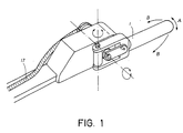
- Said lever 1 ends with a fork 2, provided, on the free ends of its arms 3, with through holes 4, wherein the pin 5 is coupled.
- blind hole 6 On the body of the fork 2, laterally outwardly with respect to the device, observing the same in the figure, it is further provided a blind hole 6, the function of which will be described in greater detail in the following.
- a further centrally holed sleeve 9 is placed, through which the pin 10 passes, said pin 10 being externally provided with a plate 11, said plate having a relief 12 coupling with said blind hole 6.
- Pin 10 passes through a hole 14 of the body 15 to couple with a pulley 16 of the acceleration device mounted on the vehicle to allow the driving to disabled persons, and which is not part of the invention, and for this reason it is not described in greater detail.
- a stop (not shown in the figure) is shown, determining the lever 1 and fork 2 run, necessary to determine the release of the acceleration action before prosecuting the braking action.
- spring 8 will couple again relief 12 and blind hole, now ready to start again the use of the device.
- pin 10 and plate 11 could be provided on the other side of the body 15, beyond the pulley 16 connecting with the acceleration device.
- the same pulley 16 could be replaced by different means for interaction with the acceleration device.
- FIG 3 a second embodiment of the device according to the invention is shown.
- the solution shown in figure 3 is substantially equal to the preceding one, so that corresponding parts will be indicated by the same references.
- the main difference is the fact that it is realised for a left-hander person, and that it provides a cruise control device, that could also be provided in the previous embodiment.
- Device shown in figure 3 provides a lever 1, upon which the driver acts both to accelerate and brake.
- Said lever 1 ends with an element 2, provided with a U shaped portion provided, on the free ends of its arms 3, with through holes 4, wherein the pin 5 is coupled.
- peg 6' On the body of the element 2 a peg 6' is provided, the function of which will be described in greater detail in the following.
- Pin 5 passes within an element 22, shown in the enlarged particular of the figure, providing two perpendicular sleeves, respectively 7 and 9, and a spring 8.
- Pin 10 passes through the sleeve 9. Externally to said pin 10 a plate 11 is provided, said plate having a notch 12' coupling with said peg 6'.
- a hindering spring 13 is placed, hindering the motion of the lever 1 during acceleration.
- Pin 10 passes through a hole 14 realised in the body 15 to couple with a plate 16' of the acceleration device mounted on the vehicle to allow the driving to disabled persons, and which is not part of the invention, and for this reason it is not described in greater detail.
- the "cruise control" device comprised of a plate 17, provided on one side with a pin 18 ending with a spiral spring 19, and that enters within a hole (not shown) realised in the body 15, and on the other side ending with a peg 20, that will couple with one of a plurality of circumferential holes (not shown), realised on said element 16'.
- a knob 21 is provided, coupled with said pin 18 and slidable along a slot (not shown), realised in said body 15.
- the driver wishes to use the cruise control device, he will act on the knob 21, returning the plate 17 and thus inserting the peg 20 in the suitable hole of said plurality of circumferential holes.
Landscapes
- Engineering & Computer Science (AREA)
- Chemical & Material Sciences (AREA)
- Combustion & Propulsion (AREA)
- Transportation (AREA)
- Mechanical Engineering (AREA)
- Automation & Control Theory (AREA)
- Control Of Driving Devices And Active Controlling Of Vehicle (AREA)
- Auxiliary Drives, Propulsion Controls, And Safety Devices (AREA)
- Braking Arrangements (AREA)
- Valve Device For Special Equipments (AREA)
- Braking Systems And Boosters (AREA)
- Controls For Constant Speed Travelling (AREA)
Claims (3)
- Vorrichtung zur automatischen Rücknahme des Gaspedals während der Bremsung enthaltend:dadurch gekennzeichnet,eine handbetätigte Beschleunigungseinrichtung;Mittel (16), die mit der vorgenannten handbetätigten Einrichtung zusammenwirken undSteuerhebel (1) zur Steuerung der Beschleunigung und der Bremsung, wobei die vorgenannten Steuer und Bremswirkungen in zwei zueinander wesentlich senkrechten Richtungen erfolgen;Mittel (10,11) zur Ankupplung der vorgenannten zusammenwirkenden Mittel (16) mit der vorgenannten handbetätigten Beschleumigungseinrichtung;auslösbare Kupplungsmittel (12,6), die zu den vorgenannten Ankupplungsmitteln (10,11) zugehören und auslöbar mit dem vorgenannten Stenerhebel (1) verbindbar sind;Elastische Hindermittel (8) zur Verhinderung einer Entkupplung zwischen den vorgenannten auslösbaren Ankupplungsmitteln (10,11) und dem vorgenannten Stenerhebel (11) undElastische Rückführmittel (13) zum Rückführen der Beschleunigungseinrichtung in eine Leerstellung,dass das vorgenannte Rückführmittel (13) und das vorgenannte elastsche Hindermittel aus Feder bestehen.dass die vorgenannten Ankupplungsmittel mit einem durch eine in einem Körper (15) der vorgenannten Handbeschleunigungseinrichtung vorgesehene Bohrung (14) durchgehenden Bolzen versehen ist (10), wobei der vorgenannte Bolzen (10) an einem Ende mit den vorgenannten Mitwirkmitteln (16) und an anderem Ende mit einer Platte (11) versehen ist, die auslösbar mit mit dem vorgenannten Stenerhebel (1) gekuppelt ist,dass der vorgenannte Stenerhebel (1) an seiner Hinterseite mit einer Gabel (2), die zwei Arme (3) hat, versehen ist, wobei an den Enden der Arme (3) das vorgenannte elastische Hindermittel (8) so angeordnet ist, dass eine Entkupplung zwischen dem auslösbaren Ankupplungsmittel (12,6) und dem Stenerhebel (1) verhindert wird;dass das vorgenannte auslösbare Ankupplungsmittel:einen an der Platte (11) vorgesehenen Vorsprung (12) und eine am Stenerhebel (1) vorgesehene Blindbohrung (6),einen am Stenerhebel (1) vorgeseheneh Zapfen (6') und eine an der Platte (1) vorgesrhen Aussparung (12') enthält, wobei der vorgenannte Vorsprung oder Zapfen und die vorgenannte Blindbohrung oder Aussparungwährend der Beschleunigung gekuppelt undwährend der Bremsung nicht gekuppelt sind;dass eine verstellbarer Anschlag so angeordnet ist, dass eine Entkupplung zwischen dem Stenerhebel (1) und den auslöbaren Ankupplungsmitteln (12,6) gestattet wird und
- Vorrichtung nach Anspruch 1, dadurch gekennzeichnet, dass eine Fahrt-Steuervorrichtung vorgesehen ist.
- Vorrichtung nach Ansprunch 2, dadurch gekennzeichnet, dass die Fahrt-Steuervorrichtung eine hinter der Beschleunigungseinrichtung engeordnete Platte (17) enthält, die mit Mitteln (21) zur Sicherung der Beschunigunsstelle und Mitteln (8,9) zur Mitarbeit mit den handbetätigten Bescheunigungs-und - Bremsitteln versehen ist.
Applications Claiming Priority (3)
| Application Number | Priority Date | Filing Date | Title |
|---|---|---|---|
| IT98RM000429A IT1299535B1 (it) | 1998-06-26 | 1998-06-26 | Dispositivo di sgancio automatico dell'acceleratore in fase di frenatura |
| ITRM980429 | 1998-06-26 | ||
| PCT/IT1999/000190 WO2000000362A1 (en) | 1998-06-26 | 1999-06-25 | Device for automatic release of accelerator during the braking action |
Publications (2)
| Publication Number | Publication Date |
|---|---|
| EP1089894A1 EP1089894A1 (de) | 2001-04-11 |
| EP1089894B1 true EP1089894B1 (de) | 2002-09-11 |
Family
ID=11406014
Family Applications (1)
| Application Number | Title | Priority Date | Filing Date |
|---|---|---|---|
| EP99931445A Expired - Lifetime EP1089894B1 (de) | 1998-06-26 | 1999-06-25 | Gerät zur automatischen gaspedalrücknahme während des bremsens |
Country Status (7)
| Country | Link |
|---|---|
| EP (1) | EP1089894B1 (de) |
| AU (1) | AU4797399A (de) |
| BR (1) | BR9911569A (de) |
| DE (1) | DE69902909D1 (de) |
| ES (1) | ES2184472T3 (de) |
| IT (1) | IT1299535B1 (de) |
| WO (1) | WO2000000362A1 (de) |
Families Citing this family (1)
| Publication number | Priority date | Publication date | Assignee | Title |
|---|---|---|---|---|
| US20040108161A1 (en) * | 2002-09-18 | 2004-06-10 | Calsonic Kansei Corporation | Vehicular steering operation device and method of controlling vehicle speed using vehicular steering operation device |
Family Cites Families (4)
| Publication number | Priority date | Publication date | Assignee | Title |
|---|---|---|---|---|
| DE3333258C2 (de) * | 1983-09-15 | 1985-07-11 | Ford-Werke AG, 5000 Köln | Brems-Gas-Handsteuergerät zur Bedienung eines Kraftfahrzeuges durch beinbehinderte Fahrer |
| NL8701503A (nl) * | 1987-06-26 | 1989-01-16 | Timotheus Theodorus Van Der Vl | Gecombineerd gas- rempedaal systeem. |
| US5103946A (en) * | 1990-11-06 | 1992-04-14 | Team Mfg., Inc. | Brake and accelerator controls for handicapped |
| GB2290509B (en) * | 1994-06-22 | 1998-02-11 | Jill Webber | Hand controls for disabled drivers |
-
1998
- 1998-06-26 IT IT98RM000429A patent/IT1299535B1/it active IP Right Grant
-
1999
- 1999-06-25 DE DE69902909T patent/DE69902909D1/de not_active Expired - Lifetime
- 1999-06-25 AU AU47973/99A patent/AU4797399A/en not_active Abandoned
- 1999-06-25 ES ES99931445T patent/ES2184472T3/es not_active Expired - Lifetime
- 1999-06-25 EP EP99931445A patent/EP1089894B1/de not_active Expired - Lifetime
- 1999-06-25 WO PCT/IT1999/000190 patent/WO2000000362A1/en not_active Ceased
- 1999-06-25 BR BR9911569-7A patent/BR9911569A/pt not_active IP Right Cessation
Also Published As
| Publication number | Publication date |
|---|---|
| EP1089894A1 (de) | 2001-04-11 |
| BR9911569A (pt) | 2001-05-08 |
| AU4797399A (en) | 2000-01-17 |
| DE69902909D1 (de) | 2002-10-17 |
| IT1299535B1 (it) | 2000-03-16 |
| ITRM980429A1 (it) | 1999-12-26 |
| WO2000000362A1 (en) | 2000-01-06 |
| ES2184472T3 (es) | 2003-04-01 |
| ITRM980429A0 (it) | 1998-06-26 |
Similar Documents
| Publication | Publication Date | Title |
|---|---|---|
| CN114007887B (zh) | 驾驶辅助装置 | |
| JP4887509B2 (ja) | 自動車の運転補助装置 | |
| US3975972A (en) | Adjustable pedal construction | |
| US5448928A (en) | Variable ratio parking brake lever with self-adjust cable tensioning means | |
| JP3894757B2 (ja) | 乗用型草刈り機 | |
| US5129492A (en) | Steering column mounted hand control | |
| US6701242B1 (en) | Device and method for actuating a brake system of a motor vehicle according to driving situation | |
| JP2002347687A (ja) | 自転車用コントロール装置及びシフトコントロール機構 | |
| US20030010149A1 (en) | Parking brake operating device for vehicle | |
| EP1089894B1 (de) | Gerät zur automatischen gaspedalrücknahme während des bremsens | |
| JP2008204421A (ja) | 自動車の携帯型運転補助装置 | |
| EP0071674B1 (de) | Anordnung eines Zapfwellenhebels für einen Traktor | |
| US6749535B2 (en) | Acceleration control and release device | |
| JPS62173508A (ja) | ギアシフト制御機構 | |
| KR100397852B1 (ko) | 차량의 파킹 브레이크 시스템 | |
| KR100483158B1 (ko) | 차량의 통합형 페달 | |
| US4582184A (en) | Brake control device | |
| CN109322991A (zh) | 离合器控制装置、系统及其方法和车辆 | |
| US7950489B2 (en) | Safety interlock system for left foot operated accelerator control devices | |
| JP2519031Y2 (ja) | 移動農機の走行操作装置 | |
| JPH0394461U (de) | ||
| EP0192979B1 (de) | Sperre für eine Bremssteuereinrichtung | |
| KR200149580Y1 (ko) | 자동차의역진방지장치 | |
| JPH021610Y2 (de) | ||
| JP3067074B2 (ja) | 操作レバー支持構造 |
Legal Events
| Date | Code | Title | Description |
|---|---|---|---|
| PUAI | Public reference made under article 153(3) epc to a published international application that has entered the european phase |
Free format text: ORIGINAL CODE: 0009012 |
|
| 17P | Request for examination filed |
Effective date: 20001221 |
|
| AK | Designated contracting states |
Kind code of ref document: A1 Designated state(s): DE ES GB PT |
|
| 17Q | First examination report despatched |
Effective date: 20010410 |
|
| GRAG | Despatch of communication of intention to grant |
Free format text: ORIGINAL CODE: EPIDOS AGRA |
|
| GRAG | Despatch of communication of intention to grant |
Free format text: ORIGINAL CODE: EPIDOS AGRA |
|
| GRAH | Despatch of communication of intention to grant a patent |
Free format text: ORIGINAL CODE: EPIDOS IGRA |
|
| GRAH | Despatch of communication of intention to grant a patent |
Free format text: ORIGINAL CODE: EPIDOS IGRA |
|
| GRAA | (expected) grant |
Free format text: ORIGINAL CODE: 0009210 |
|
| AK | Designated contracting states |
Kind code of ref document: B1 Designated state(s): DE ES GB PT |
|
| REG | Reference to a national code |
Ref country code: GB Ref legal event code: FG4D |
|
| REF | Corresponds to: |
Ref document number: 69902909 Country of ref document: DE Date of ref document: 20021017 |
|
| PG25 | Lapsed in a contracting state [announced via postgrant information from national office to epo] |
Ref country code: DE Free format text: LAPSE BECAUSE OF FAILURE TO SUBMIT A TRANSLATION OF THE DESCRIPTION OR TO PAY THE FEE WITHIN THE PRESCRIBED TIME-LIMIT Effective date: 20021212 |
|
| PG25 | Lapsed in a contracting state [announced via postgrant information from national office to epo] |
Ref country code: PT Free format text: LAPSE BECAUSE OF FAILURE TO SUBMIT A TRANSLATION OF THE DESCRIPTION OR TO PAY THE FEE WITHIN THE PRESCRIBED TIME-LIMIT Effective date: 20021218 |
|
| REG | Reference to a national code |
Ref country code: ES Ref legal event code: FG2A Ref document number: 2184472 Country of ref document: ES Kind code of ref document: T3 |
|
| PLBE | No opposition filed within time limit |
Free format text: ORIGINAL CODE: 0009261 |
|
| STAA | Information on the status of an ep patent application or granted ep patent |
Free format text: STATUS: NO OPPOSITION FILED WITHIN TIME LIMIT |
|
| 26N | No opposition filed |
Effective date: 20030612 |
|
| PGFP | Annual fee paid to national office [announced via postgrant information from national office to epo] |
Ref country code: GB Payment date: 20060621 Year of fee payment: 8 |
|
| PGFP | Annual fee paid to national office [announced via postgrant information from national office to epo] |
Ref country code: ES Payment date: 20060720 Year of fee payment: 8 |
|
| GBPC | Gb: european patent ceased through non-payment of renewal fee |
Effective date: 20070625 |
|
| PG25 | Lapsed in a contracting state [announced via postgrant information from national office to epo] |
Ref country code: GB Free format text: LAPSE BECAUSE OF NON-PAYMENT OF DUE FEES Effective date: 20070625 |
|
| REG | Reference to a national code |
Ref country code: ES Ref legal event code: FD2A Effective date: 20070626 |
|
| PG25 | Lapsed in a contracting state [announced via postgrant information from national office to epo] |
Ref country code: ES Free format text: LAPSE BECAUSE OF NON-PAYMENT OF DUE FEES Effective date: 20070626 |