EP1089823B1 - Elektrodenanordnungen zur erzeugung funktioneller feldbarrieren in mikrosystemen - Google Patents
Elektrodenanordnungen zur erzeugung funktioneller feldbarrieren in mikrosystemen Download PDFInfo
- Publication number
- EP1089823B1 EP1089823B1 EP99929320A EP99929320A EP1089823B1 EP 1089823 B1 EP1089823 B1 EP 1089823B1 EP 99929320 A EP99929320 A EP 99929320A EP 99929320 A EP99929320 A EP 99929320A EP 1089823 B1 EP1089823 B1 EP 1089823B1
- Authority
- EP
- European Patent Office
- Prior art keywords
- channel
- electrode
- electrodes
- particles
- micro
- Prior art date
- Legal status (The legal status is an assumption and is not a legal conclusion. Google has not performed a legal analysis and makes no representation as to the accuracy of the status listed.)
- Expired - Lifetime
Links
Images


Classifications
-
- B—PERFORMING OPERATIONS; TRANSPORTING
- B01—PHYSICAL OR CHEMICAL PROCESSES OR APPARATUS IN GENERAL
- B01L—CHEMICAL OR PHYSICAL LABORATORY APPARATUS FOR GENERAL USE
- B01L3/00—Containers or dishes for laboratory use, e.g. laboratory glassware; Droppers
- B01L3/50—Containers for the purpose of retaining a material to be analysed, e.g. test tubes
- B01L3/502—Containers for the purpose of retaining a material to be analysed, e.g. test tubes with fluid transport, e.g. in multi-compartment structures
- B01L3/5027—Containers for the purpose of retaining a material to be analysed, e.g. test tubes with fluid transport, e.g. in multi-compartment structures by integrated microfluidic structures, i.e. dimensions of channels and chambers are such that surface tension forces are important, e.g. lab-on-a-chip
- B01L3/502761—Containers for the purpose of retaining a material to be analysed, e.g. test tubes with fluid transport, e.g. in multi-compartment structures by integrated microfluidic structures, i.e. dimensions of channels and chambers are such that surface tension forces are important, e.g. lab-on-a-chip specially adapted for handling suspended solids or molecules independently from the bulk fluid flow, e.g. for trapping or sorting beads, for physically stretching molecules
-
- B—PERFORMING OPERATIONS; TRANSPORTING
- B01—PHYSICAL OR CHEMICAL PROCESSES OR APPARATUS IN GENERAL
- B01F—MIXING, e.g. DISSOLVING, EMULSIFYING OR DISPERSING
- B01F33/00—Other mixers; Mixing plants; Combinations of mixers
- B01F33/30—Micromixers
- B01F33/3031—Micromixers using electro-hydrodynamic [EHD] or electro-kinetic [EKI] phenomena to mix or move the fluids
-
- B—PERFORMING OPERATIONS; TRANSPORTING
- B01—PHYSICAL OR CHEMICAL PROCESSES OR APPARATUS IN GENERAL
- B01F—MIXING, e.g. DISSOLVING, EMULSIFYING OR DISPERSING
- B01F33/00—Other mixers; Mixing plants; Combinations of mixers
- B01F33/30—Micromixers
- B01F33/3032—Micromixers using magneto-hydrodynamic [MHD] phenomena to mix or move the fluids
-
- B—PERFORMING OPERATIONS; TRANSPORTING
- B03—SEPARATION OF SOLID MATERIALS USING LIQUIDS OR USING PNEUMATIC TABLES OR JIGS; MAGNETIC OR ELECTROSTATIC SEPARATION OF SOLID MATERIALS FROM SOLID MATERIALS OR FLUIDS; SEPARATION BY HIGH-VOLTAGE ELECTRIC FIELDS
- B03C—MAGNETIC OR ELECTROSTATIC SEPARATION OF SOLID MATERIALS FROM SOLID MATERIALS OR FLUIDS; SEPARATION BY HIGH-VOLTAGE ELECTRIC FIELDS
- B03C5/00—Separating dispersed particles from liquids by electrostatic effect
- B03C5/02—Separators
- B03C5/022—Non-uniform field separators
- B03C5/026—Non-uniform field separators using open-gradient differential dielectric separation, i.e. using electrodes of special shapes for non-uniform field creation, e.g. Fluid Integrated Circuit [FIC]
-
- C—CHEMISTRY; METALLURGY
- C12—BIOCHEMISTRY; BEER; SPIRITS; WINE; VINEGAR; MICROBIOLOGY; ENZYMOLOGY; MUTATION OR GENETIC ENGINEERING
- C12M—APPARATUS FOR ENZYMOLOGY OR MICROBIOLOGY; APPARATUS FOR CULTURING MICROORGANISMS FOR PRODUCING BIOMASS, FOR GROWING CELLS OR FOR OBTAINING FERMENTATION OR METABOLIC PRODUCTS, i.e. BIOREACTORS OR FERMENTERS
- C12M33/00—Means for introduction, transport, positioning, extraction, harvesting, peeling or sampling of biological material in or from the apparatus
-
- C—CHEMISTRY; METALLURGY
- C12—BIOCHEMISTRY; BEER; SPIRITS; WINE; VINEGAR; MICROBIOLOGY; ENZYMOLOGY; MUTATION OR GENETIC ENGINEERING
- C12M—APPARATUS FOR ENZYMOLOGY OR MICROBIOLOGY; APPARATUS FOR CULTURING MICROORGANISMS FOR PRODUCING BIOMASS, FOR GROWING CELLS OR FOR OBTAINING FERMENTATION OR METABOLIC PRODUCTS, i.e. BIOREACTORS OR FERMENTERS
- C12M47/00—Means for after-treatment of the produced biomass or of the fermentation or metabolic products, e.g. storage of biomass
- C12M47/04—Cell isolation or sorting
-
- B—PERFORMING OPERATIONS; TRANSPORTING
- B01—PHYSICAL OR CHEMICAL PROCESSES OR APPARATUS IN GENERAL
- B01L—CHEMICAL OR PHYSICAL LABORATORY APPARATUS FOR GENERAL USE
- B01L2200/00—Solutions for specific problems relating to chemical or physical laboratory apparatus
- B01L2200/06—Fluid handling related problems
- B01L2200/0647—Handling flowable solids, e.g. microscopic beads, cells, particles
- B01L2200/0652—Sorting or classification of particles or molecules
-
- B—PERFORMING OPERATIONS; TRANSPORTING
- B01—PHYSICAL OR CHEMICAL PROCESSES OR APPARATUS IN GENERAL
- B01L—CHEMICAL OR PHYSICAL LABORATORY APPARATUS FOR GENERAL USE
- B01L2200/00—Solutions for specific problems relating to chemical or physical laboratory apparatus
- B01L2200/06—Fluid handling related problems
- B01L2200/0647—Handling flowable solids, e.g. microscopic beads, cells, particles
- B01L2200/0668—Trapping microscopic beads
-
- B—PERFORMING OPERATIONS; TRANSPORTING
- B01—PHYSICAL OR CHEMICAL PROCESSES OR APPARATUS IN GENERAL
- B01L—CHEMICAL OR PHYSICAL LABORATORY APPARATUS FOR GENERAL USE
- B01L2300/00—Additional constructional details
- B01L2300/08—Geometry, shape and general structure
- B01L2300/0809—Geometry, shape and general structure rectangular shaped
- B01L2300/0816—Cards, e.g. flat sample carriers usually with flow in two horizontal directions
-
- B—PERFORMING OPERATIONS; TRANSPORTING
- B01—PHYSICAL OR CHEMICAL PROCESSES OR APPARATUS IN GENERAL
- B01L—CHEMICAL OR PHYSICAL LABORATORY APPARATUS FOR GENERAL USE
- B01L2300/00—Additional constructional details
- B01L2300/08—Geometry, shape and general structure
- B01L2300/0861—Configuration of multiple channels and/or chambers in a single devices
- B01L2300/0864—Configuration of multiple channels and/or chambers in a single devices comprising only one inlet and multiple receiving wells, e.g. for separation, splitting
-
- B—PERFORMING OPERATIONS; TRANSPORTING
- B01—PHYSICAL OR CHEMICAL PROCESSES OR APPARATUS IN GENERAL
- B01L—CHEMICAL OR PHYSICAL LABORATORY APPARATUS FOR GENERAL USE
- B01L2400/00—Moving or stopping fluids
- B01L2400/04—Moving fluids with specific forces or mechanical means
- B01L2400/0403—Moving fluids with specific forces or mechanical means specific forces
- B01L2400/0409—Moving fluids with specific forces or mechanical means specific forces centrifugal forces
-
- B—PERFORMING OPERATIONS; TRANSPORTING
- B01—PHYSICAL OR CHEMICAL PROCESSES OR APPARATUS IN GENERAL
- B01L—CHEMICAL OR PHYSICAL LABORATORY APPARATUS FOR GENERAL USE
- B01L2400/00—Moving or stopping fluids
- B01L2400/04—Moving fluids with specific forces or mechanical means
- B01L2400/0403—Moving fluids with specific forces or mechanical means specific forces
- B01L2400/0415—Moving fluids with specific forces or mechanical means specific forces electrical forces, e.g. electrokinetic
-
- B—PERFORMING OPERATIONS; TRANSPORTING
- B01—PHYSICAL OR CHEMICAL PROCESSES OR APPARATUS IN GENERAL
- B01L—CHEMICAL OR PHYSICAL LABORATORY APPARATUS FOR GENERAL USE
- B01L3/00—Containers or dishes for laboratory use, e.g. laboratory glassware; Droppers
- B01L3/50—Containers for the purpose of retaining a material to be analysed, e.g. test tubes
- B01L3/502—Containers for the purpose of retaining a material to be analysed, e.g. test tubes with fluid transport, e.g. in multi-compartment structures
- B01L3/5027—Containers for the purpose of retaining a material to be analysed, e.g. test tubes with fluid transport, e.g. in multi-compartment structures by integrated microfluidic structures, i.e. dimensions of channels and chambers are such that surface tension forces are important, e.g. lab-on-a-chip
- B01L3/502746—Containers for the purpose of retaining a material to be analysed, e.g. test tubes with fluid transport, e.g. in multi-compartment structures by integrated microfluidic structures, i.e. dimensions of channels and chambers are such that surface tension forces are important, e.g. lab-on-a-chip characterised by the means for controlling flow resistance, e.g. flow controllers, baffles
Definitions
- the invention relates to electrode assemblies for the production functional field barriers in microsystems used for manipulation suspended particles are set up, in particular functional microelectrodes for dielectrophoretic deflection of microscopic particles, and microsystems with equipped with such electrode assemblies and their Uses.
- the manipulation of suspended particles in fluidic microsystems is well known and used for example by G. Fuhr et al. in "NaturBiben", Vol. 81, 1994, p. 528 ff., Described.
- the microsystems in particular form channel structures, that of a suspension liquid with the flowing through the manipulating particles.
- These channel structures have a rectangular cross-sectional area, the lower and upper channel walls being in operative position (Floor and top surfaces) a greater width than the have lateral channel walls (side surfaces).
- the channel structures are mounted on the channel walls microelectrodes, which are exposed to high-frequency electric fields become.
- each act two electrode bands together, on opposite canal walls with each the same shape and orientation are appropriate.
- the Straight electrode bands run, for example, parallel to Channel orientation or flow direction of the suspension liquid in the respective channel section or under a predetermined Angle at an angle to the channel orientation.
- the electrode bands possess for effective and safe training of the polarization forces a length at the particles to be manipulated, the the characteristic dimension of the particles around Multiple (factor about 20 to 50) exceeds.
- the conventional microsystems have disadvantages in terms of the effectiveness of the generation of polarization forces, the Stability and life of the microelectrodes and the limited Ability to use force gradients within the channel structure to create. These disadvantages are particularly associated with formed over relatively long lengths in the channel Electrode bands together. The longer an electrode band is, the longer is a passing particle in the Range of action of the electrode band, so that the effectiveness the respective microelectrode or generated by them Field barrier rises. On the other hand, the long electrode bands also more susceptible to interference. Due to manufacturing defects or mechanical stresses can occur interruptions which lead to electrode failure. Further, the microelectrodes became so far to achieve a consistent over the channel length and thus reproducible force action on said straight electrode design limited.
- the object of the invention is to improve Microsystems for dielectrophoretic particle deflection to create, with which the disadvantages of conventional Microsystems are overcome and in particular an extended Own and enable scope of application also over shorter channel sections to produce effective field barriers.
- the object of the invention is also novel Applications of such microsystems indicated.
- a microsystem according to the invention is in particular set up, in the microsystem field barriers along to produce predetermined reference surfaces, at least extend partially across the width of a channel in the microsystem and predetermined curvatures relative to the longitudinal extent of the channel, to the flow direction of the suspension liquid in the channel or to the direction of movement of the (not deflected) Possess particles.
- the term "reference surface” is used in not just a two-dimensional structure in this context but a space area on which the field effect extends the respective microelectrode and in which the Field barrier for the dielectric influence of the microscopic Particles in the microsystem is formed.
- This room area corresponds essentially to a range of the Field lines of effective microelectrodes is interspersed, and extends with cooperating pairs of microelectrodes as curved hypersurface between the microelectrodes or at single-acting microelectrodes as hypersurface, which the Field line distribution spans the single-acting microelectrode.
- the reference surfaces define the locations where polarization forces occur effectively generated in the microscopic particles can be.
- the microelectrodes are formed that the reference surfaces depending on the desired function the respective microelectrodes a predetermined curvature in Reference to the direction of movement of the particles in the microsystem possess, so that an optimal interaction of the polarization forces and the mechanical forces is achieved.
- curvature refers to not on the curvature of field lines on straight microelectrodes by the emergence of the field lines in the adjacent Room. The curvature designates rather the design of the Microelectrodes formed field barriers.
- the field barriers with the invention curved reference surfaces are preferably after one of the following three Basic shapes designed.
- a first variant there is a inventive electrode arrangement of at least one band-shaped, curved microelectrode, which is located on the wider channel wall (bottom and / or top surface) at least partially extends over the channel width.
- At a second Variant is provided at least one microelectrode, the the narrower channel wall (side surface) is attached.
- the third variant has at least one microelectrode the bottom and / or top surface of the channel and at least one Auxiliary electrode at a distance from the ground or side surface of the canal attached.
- the auxiliary electrode provides a deformation that of the microelectrode or the microelectrodes the ground or side surfaces of the channel outgoing field lines, so that the inventive curved reference surfaces formed become.
- the respective electrodes Mocroelectrodes, auxiliary electrodes
- the electrode arrangements are also called Three-dimensional electrode arrangements referred to, as doing Microelectrodes emerging from the planes of the soil or side surfaces of the channel protrude or from these are spaced apart.
- the invention thus relates to the optimization of microelectrodes in terms of their effect on suspended particles, which may comprise natural or synthetic particles, e.g. for generating maximum forces at the same time minimized electrical losses.
- the invention has the following advantages.
- the design the microelectrode may e.g. to the flow profile in the Be adapted to suspension liquid.
- This provides the advantage that the microelectrodes are made shorter and however, can be designed to produce smaller barriers the same effectiveness as conventional microelectrodes in the form of straight ribbons.
- This has an advantageous effect on the life and functionality of the microelectrodes and thus the entire microsystems.
- the space available in a microsystem can be used more effectively.
- electrode arrangements with which gradients and thus depending on the respective Channel area different strong forces can be generated.
- the field barriers of Microelectrodes are designed so that the particles in the Greater polarization forces are exerted in the middle of the channel as at the edge of the canal.
- the inventive design of field barriers along curved Reference surfaces also allow the creation of novel Applications of microsystems, in particular for steering suspended particles in certain channel areas, for sorting of suspended particles after their passive electrical Properties or for collection or holding suspended Particles in certain channel sections.
- microelectrodes with a geometric Mold for holding the particles in a solution stream or designed to generate a particle formation. All these applications provide one over the Microsystem non-contact manipulation of the suspended Particles, which is particularly essential for the manipulation of biological Cells or cell components.
- Preferred applications are in microsystems technology Separation, manipulation, loading, fusion, permeation, pairing and aggregate formation of microscopic ones Particles.
- the particle movement in a microsystem with Electrode forms according to the invention can, under the action of centrifugal and / or gravitational forces.
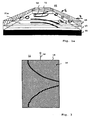
- Fig. 1a shows in a schematic form by way of example the execution of microelectrodes for generating field barriers in microchannels.
- the fluidic microsystem 20 is fragmentary in elevated perspective view of a channel structure shown.
- the channel 21 is separated by two at a distance
- the channel width and height amount to approx. 200 or 40 ⁇ m, but can also be smaller.
- Such structures will be for example, with the known per se processing techniques of semiconductor technology.
- the substrate 22 forms the bottom surface 21a of the channel 21. Accordingly, the Cover surface 21b (for reasons of clarity not separately highlighted) formed by the cover part 24.
- the electrode arrangement 10 consists of microelectrodes 11, 12, on the Floor surface 21a or on the top surface 21b are mounted.
- Each of the microelectrodes 11, 12 consists of curved electrode bands, which will be described in more detail below.
- the electrode bands form an electrode structure, which will be explained in detail below with reference to FIG. 2 becomes.
- the other embodiments described below According to the invention electrode assemblies can according to attached to the bottom, top and / or side surfaces of the channel 21 be.
- the microchannel 21 is a suspension liquid flows through (in the picture from right to left), in the particle 30 are suspended.
- the electrode arrangement shown in Fig. 1a 10 has the task of the particles 30 of different trajectories within the channel to lead a mean trajectory according to arrow A. To do this the microelectrodes 11, 12 in such a way with electrical potentials acted on that in the channel electric field barriers form, which are the particles flowing in from the right towards the Force channel center (arrow directions B).
- the typical dimensions of the microelectrodes 11, 12 are included a width of 0.1 to several tens of microns (typically 5 ... 10 ⁇ m), a thickness of 100 nm to a few micrometers (typically 200 nm) and a length of up to several one hundred microns.
- the interior of the channel 21 is through the on the top and bottom of the parts 23, 24 processed Electrodes due to the small thickness of the electrodes not limited.
- the part 23 is a spacer whose structuring the lateral channel walls forms.
- the microelectrodes 11, 12 are by means of high-frequency electrical Signals (typically with a frequency in the MHz range and an amplitude in the volt range).
- the respective opposite electrodes 11a, 11b form a drive pair, although also in-plane electrodes in their control (phase, frequency, amplitude) interact can.
- the hydrodynamically open channel 21 can be over structure and compartmentalize the electric fields, compartmentalize or can be the trajectories of the particles in the passive flow field. Furthermore, it is possible to retard the particles despite permanent flow or positionally stable without touching a surface to position.
- FIGS. 1b to 1c show the basic forms of field barriers or electromagnetic limitations associated with the invention Implemented electrode arrangements according to the above variants become.
- the illustrations are schematic representations of the Reference surfaces on which the field barriers with inventive Microelectrodes are formed. For clarity are only parts of the side surface (spacer 23) and the Bottom surface 21 a of the channel, the microelectrodes 11, 12 and the Course of the reference surfaces (hatched) shown.
- the field barrier in Channel between two curved microelectrodes 11, 12 on the Bottom and top surfaces of the channel formed (Fig. 1b).
- the reference surface the field barrier (hatched) runs accordingly as curved, perpendicular to the bottom and top surfaces standing area.
- the microelectrodes 11, 12, for example according to a certain hyperbolic flow profile curved (see below) so the reference surface forms the Section of the lateral surface of a hyperbolic cylinder. If the microelectrodes 11, 12 are not arranged exactly one above the other are, so the reference surface is still in relation to the Bottom and top surfaces of the channel skewed.
- Fig. 1c spans the reference surface shown hatched a space area that is interspersed by field lines, the from a microelectrode 11 on a side surface of the channel to a microelectrode 12 on the opposite side surface run.
- the first Microelectrode 11 has a larger area than the second Microelectrode 12, so that in the latter a field line concentration occurs.
- the second microelectrode 12 is larger than near the first microelectrode 11 (see also Fig. 9).
- Fig. 1d The above third variant with a three-dimensional Electrode arrangement is illustrated in Fig. 1d.
- the microelectrodes 11, 12 are located on the floor or top surfaces of the channel, while the auxiliary electrode 13 with a suitable Holder is arranged in the middle of the channel (see also Fig. 10).
- the auxiliary electrode 13 By the auxiliary electrode 13, the field lines between the Microelectrodes 11, 12 distorted, so that hatched shown, curved reference surface (partially shown) results.
- the illustrated reference surfaces merely represent the position the field barriers, without those in the corresponding areas acting forces, i. the height of the field barriers, too illustrate.
- the forces acting depend essentially on the field line density and the passive electrical properties the particles to be manipulated in the respective channel region from.
- the functional field barriers according to the invention are thus by the geometric shape of the cooperating Microelectrodes both in terms of their shape (curvatures etc.), since the dielectrophoretic repulsive forces substantially perpendicular to the reference surfaces, as well as in Reference to their areas (field line density) influenced.
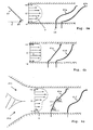
- FIG. 2 An inventive electrode assembly 10 according to the above first variant is shown in Fig. 2.
- Fig. 2 On the bottom surface 21 a of the laterally bounded by the spacer 23 Channels of a microsystem are microelectrodes 11a, 11b arranged.
- the microelectrodes 11a, 11b are connected via the control lines 14 subjected to high-frequency electrical potentials and act to form a so-called particle funnel as follows together.
- the electrode assembly 10 is provided to initially in the entire channel width or the entire channel volume inflowing Particles 30a contactless on a center line of the Focus on channels as determined by the position of the particle 30b is illustrated.
- the advantage of this arrangement exists in the optimization of electrode bands in terms of Safety of the distraction (focusing) of the suspended Particles shortening the electrode assembly in Channel longitudinal direction and the reduction of electrical losses at the microelectrodes.
- the basic idea the design of the microelectrodes therein, the curvature of the Reference surfaces formed by the field barrier to the flow forces in the channel.
- microsystems with channel dimensions below 500 microns namely because of at These dimensions of low Reynolds numbers make the training more laminar Currents with predetermined flow profiles.
- the Flow velocity near the channel walls is lower as in the middle of the channel (flow velocity immediately at the channel wall equal to zero). This will occur in the vicinity the channel walls lower flow forces than in the middle of the channel on. This allows manipulation of the particles at the channel edge with lower polarization forces or steeper against the flow forces directed polarization forces as in the middle of the canal. The interaction of the flow and polarization forces will be explained below.
- the forces acting on the particles are illustrated in FIG. 2 by way of example in individual sections of the microelectrode 11a.
- the respective total force is composed of the electrically induced repulsive force F P (polarization force) and the driving force F S , which is exerted by the flow of the suspension liquid or also from the outside (eg in centrifugal systems as a centrifugal force).
- the resulting total force F R results from vector addition of the forces F P and F S. If the vector of the total force F R does not intersect the field barrier of the microelectrode 11a, then a particle is deflected safely.
- the force diagrams in Fig. 2 illustrate that the driving force F S increases towards the center of the channel.
- the angle between the orientation of the microelectrode 11a and the channel longitudinal direction changes from a steeper angle at the channel edge to a narrow angle (nearly parallelism) in the channel center.
- microelectrodes 11a, 11b are thus dependent on Flow profile formed curved.
- Flow profile formed curved In the illustrated Embodiment consists of each of the band-shaped microelectrodes from a plurality of respective straight electrode sections.
- a modified embodiment can also be a steady Curvature be provided. The curvature is corresponding to the parabolic or laminar flows hyperbolic flow profiles corresponding also parabolic or hyperbolic.
- microelectrodes 11a, 11b form the field barriers according to the invention along a curved reference surface.
- microelectrodes 11c, 11d are not provided in practice and serve in the representation of the comparison of an inventive Arrangement of polygonal curved microelectrodes with straight electrode bands of the same deflection power. It shows that the microelectrodes 11a, 11b are significantly shorter.
- the narrow electrode bands shown in Fig. 2 are opposite Manufacturing defects and local interruptions very sensitive.
- a hairline crack at the base of a band-shaped microelectrode leads to failure of the entire microelectrode. That can be remedied with an electrode design, the schematic in Fig. 3 is shown.
- the structuring described in connection with FIG. and masking technology may also be used in the other embodiments of the invention.
- FIG. 3 shows a microelectrode 11 with a control line 14.
- the electrode 11 consists of an electrically conductive layer 15, which carries an electrically non-conductive insulation or cover layer 16.
- the insulating layer 16 has a structuring in the form of recesses, through which the layer 15 is exposed. In Fig. 3, the insulation layer 16 is hatched and the (eg metallic) layer 15 drawn in black. The structuring of the insulating layer takes place in accordance with the desired shape of microelectrodes, which in the illustrated example are designed to form a particle funnel as in FIG. 2.
- the electric field lines pass from the metallic layer 15 in the channel only in the areas of the recesses, so that in turn field barriers are formed with application-dependent curved reference surfaces.
- the layer 15 has, for example, a thickness of approx. 50 nm up to a few ⁇ m, typically approx. 200 nm.
- the thickness of the insulation layer is approx. 100 nm up to a few ⁇ m.
- the insulating layer is preferably made of biocompatible materials (eg, oxides, SiO 2 , SiNO 3 and the like, polymers, tantalum compounds or the like).
- FIG. 4a to 4c A further embodiment of an electrode arrangement according to the invention 10 according to the above first variant will be described below with reference to Figs. 4a to 4c explained.
- An important application of fluidic microsystems exists in sorting the suspended particles in dependence of their passive electrical properties (hereinafter also as polarization properties in negative dielectrophoresis designated).
- the polarization properties depend on the dielectric properties of the particles and their dimensions from.
- the dielectric properties of biological cells are a sensitive indicator of certain cell characteristics or changes, which in themselves, for example, by a size observation could not be detected.
- Particle sorting depending on their passive electrical properties is based on the following principle. Whether a particle can pass the field barrier formed by a sorting electrode depends on whether or not the resultant force from the driving force F s and the polarizing force F P (see above) crosses the field barrier. If the resulting total force F R passes through the field barrier, the particle moves in that direction, ie the sorting electrode is passed. However, if the resultant force F R is in an upstream region with respect to the sorting electrode, then the particle will move in that direction and will not be able to pass through the sorting electrode. The resulting force F R depends, as explained above, on the flow velocity of the channel and thus on the x-position of the particle. Towards the center of the channel, the flow rate increases.
- microelectrodes 41a, 41b are used with a curvature as a function of the flow profile according to the principles explained with reference to FIG. 2.
- FIG. 4a shows two examples of curved microelectrodes 41a, FIG. 41b on the bottom surface 21a of a channel between lateral Spacers 23.
- the channel becomes in y-direction from left to right flows through, the arrows v the velocity flow profile in the channel.
- Upstream of the the actual sorting electrode 41a or 41b is a rectilinear microelectrode 47 whose task is the inflowing particles 30 from the left to a start line s to focus.
- the microelectrode 47 can also act as a focusing electrode be designated. It is as shown straight, conventional deflection or curved executed.
- Downstream of the focusing electrode 47 is one of Sorting electrodes 41a or 41b arranged, the task in it exists, the inflowing particles 30 depending on their Polarization properties with respect to the x direction to transfer different tracks in the channel.
- the particles with a high polarizability 30a should be different from the particles with a low polarizability 30b in the y direction move on different tracks.
- the sorting electrode 41a is arranged for a linear force action.
- the curvature of the microelectrode is designed in accordance with the flow profile. At low flow velocities, a high angle of attack between the microelectrode and the y-direction and at relatively high flow velocities a smaller angle of attack is formed.
- the microelectrode 41a thus has an S-shape with a turning point in the middle of the channel. After passage of the sorting electrode 41a, there is a linear relationship between the x-coordinate of the particle and its polarizability. If a non-linear sorting effect is intended, the microelectrode may be curved like the sorting electrode 11b.
- the curvature is weaker than in the case of the sorting electrode 11a, so that the influence of the driving force F s is not compensated by the flow velocity.
- This design can be used in particular for the separation of two particle types with different polarizabilities.
- sorting electrodes 41c, 41d are provided as shown in FIG. 4b.
- the flow rate initially increases from the channel edge and then remains substantially constant in a central region of the channel.
- the sorting electrode 41a has a straight band shape in the middle region and curvatures at the ends to take account of the changing driving force F s .
- the sorting electrode 41d is curved. From the approach of the sorting electrode 41d at the control terminal 14 towards the end, there is an increasing effect of the field barrier.
- the shape of the sorting electrodes can also be more complicated Flow profiles are adapted, as shown in Fig. 4c is.
- a first channel 211 opens with a high flow rate and a second channel 212 with a lower flow velocity into a common Channel 21. Due to the laminarity of the flow that remains Flow profile also in the common flow initially receive. Accordingly, the sorting electrodes 41e and 41f, respectively to achieve a specific linear or nonlinear Sorting effect formed curved.
- the lower the flow rate the larger the angle of attack between the direction of the microelectrode (alignment of the reference surface) and the channel longitudinal direction (y-direction).
- FIGS. 4b and 4c for clarity, the Focusing electrode 17 shown in FIG. 4a not shown.
- sorting electrodes For particle sorting with respect to different feature groups can several sorting electrodes according to FIG. 4 in the channel direction be arranged consecutively.
- Each sorting electrode is with a characteristic potential or Potential course acted upon at a predetermined frequency. For example, relatively low frequencies (in the range of approximately 10 kHz) for sorting with respect to different dielectric membrane properties and high frequencies (above 100 kHz) for sorting depending on the cytoplasmic conductivity of biological cells used become.
- the gradient electrode 51 a is closed by a closed formed a triangular area guided electrode band. With increasing distance from the control line 14 is the field line density low according to the fanning out of the triangle. The same applies to the gradient electrode 51b with two divergent subbands 511b and 512b.
- fluidic microsystems Another important application of fluidic microsystems is in collecting and at least temporarily arranging particles or particle groups in suspensionswashkeits suströmten Channel.
- electrode arrangements according to the invention designed as a target, as in the following with reference to Figs. 6 to 8 will be explained.
- Fig. 6a shows the basic shape of a target electrode. Again it is only a microelectrode on the bottom or top surface a channel shown with a second microelectrode on the opposite channel side cooperates.
- a target 61a consists of an electrode band with an angle section 611a and a feeding section 612a.
- the angle section 611a forms a flow direction (x-direction) pointing angle.
- the opening angle of the angle section 611a will depend on the shape of the fish to be caught Particle selected and is preferably less than 90 °, e.g. in the range of 20 to 60 °.
- the opposite Angular sections of cooperating electrodes form one for the particles 30 to be captured also under the action of the driving force Barrier passable by the flow.
- the feed section 612a is defined by a Insulation layer 16 electrically ineffective.
- Fig. 6b shows a modified form of a target 61b, the corresponding of the cover technique explained above with reference to FIG is.
- the electrically effective angle section 611b is formed by a recess in the insulating layer 16, through a deeper metallic layer 15 out to the suspension liquid with the particles is open.
- Figs. 6c and 6d show corresponding trapping electrodes 61c and 61d each having a plurality of angle sections 611c or 611d. These angle sections are in turn for catching oncoming particle 30 is established.
- the angle sections 611c and 611d transversely to the channel longitudinal direction (x-direction) can be in the different Channel areas flowing particles are selectively collected.
- a target electrode 61c or 61d is advantageously with one of the sorting electrodes according to FIGS. 4a to 4c combined.
- the sorted particles are separated in the individual Catch areas of the trapped collected.
- the target 61d substantially corresponds to the target 61c, wherein said masking technique has been implemented.
- the fishing electrodes 61c and 61d are particularly well suited a series of particles in the suspension stream after Form a start line from which the particles turn off the control potential of the target simultaneously continuous flow.
- Fig. 6e shows another embodiment of a target 61e, in which also a plurality of angle sections 611e provided for collection or collection different sized particles or different sized aggregates are set up from these.
- FIG. 7a The accumulation of a particle group 300 with a target electrode 71a is illustrated in FIG. 7a.
- This embodiment of a The target is different from the target according to Fig. 6a only by the dimensions. This design is suitable especially good for the formation of particle aggregates.
- This design is suitable especially good for the formation of particle aggregates.
- FIGS. 4a to 4c preferably realized.
- the electrode arrangement according to FIG. 7b is for separate collection of particles or particle groups from the suspension flow set up in the channel, referring to their Distinguish flow path in x-direction.
- the Mikroelektrodenanodnung 71b includes a plurality of partial trapping electrodes each with an angular portion 711b, which are separately controllable. at Combination of such a target arrangement with a Sorting arrangement according to FIGS. 4a to 4c can with special Advantage the following procedure be realized.
- a particle mixture passing through the channel in the microsystem flows, depending on the passive electrical Properties of the particles sorted and thus different, directed in the x-direction spaced apart webs. Then the particle-specific collection of the in the individual webs flowing particles with a target according to Fig. 7b.
- the previously sorted particles can be groupwise in the microsystem.
- a split into several Subchannels are made, in which the groups of particle types specific be steered.
- Fig. 7c shows another target electrode 71c for generating a predetermined particle formation.
- FIGS. 6 and 7 can vary depending on the application Channel width or extend only over parts of the channel.
- An electrode arrangement can be used for individual electrodes Particles and / or be provided for particle groups.
- FIG. 8a Further embodiments of combined sorting and collecting electrodes are in plan view of the bottom surface 21a of a illustrated by the spacers 23 limited channel of FIG. 8.
- the channel is in the y-direction of the suspension liquid perfused with suspended particles.
- a planar microelectrode 81a acts on the bottom surface 21a with a straight, band-shaped microelectrode 82a (dashed line drawn) on the opposite top surface of the Channels together.
- the planar microelectrode 81a is through the prepared above cover technology.
- a metallic one Layer carries an insulating layer 86 with a recess according to the shape of the microelectrode 81a (drawn in black).
- the field lines between the microelectrodes 81a and 82a extend transversely to the flow direction in an inhomogeneous manner, so that an asymmetric field barrier or again a according to the invention curved reference surface results.
- In the middle of the canal is the field line density largest, so that the electric generated forces in the region of the highest flow velocity lie.
- Fig. 8b will turn a field barrier formed with a curved reference surface.
- the microelectrodes 81b, 82b are both linear or band-shaped executed and not opposite, but offset each other arranged.
- FIG. 8c An electrode assembly for forming particle aggregates is shown in Fig. 8c.
- the microelectrodes 81c, 82c form a series of side-by-side, funnel-shaped particle trap.
- Each particle trap 11 is crossed by a field barrier formed in the flow direction initially funnel-shaped narrowed and then into a straight channel section 812 empties.
- the channel section is sized so that two particles can be arranged one behind the other in the flow direction.
- the particles form Aggregate (so-called pair loading in the flow direction).
- the embodiment according to FIG. 8d is modified in such a way that that a couple loading takes place transversely to the flow direction.
- the individual catcher elements 811d with input side Formed electrode tips 813d with which an additional Barrier effect or filter effect is achieved and already existing aggregates or larger particles 30d of an arrangement in the target 81d are excluded.
- FIG. 9 A further embodiment of an electrode arrangement according to the invention according to the above second variant is in Fig. 9 shown.
- the microsystem 20 is between the spacers 23 a channel 21 formed by a partition wall 231 in Sub-channels 211 and 212 is divided.
- the partition wall 231 has an opening 232 in the area on the side surfaces of the channel 21, the microelectrodes 91 and 92 are mounted.
- the microelectrodes 91 and 92 are so-called three-dimensional or high electrodes attached to the side surfaces of the planes the bottom and top surfaces of the channel 21 protrude.
- the production the microelectrodes 91 and 92 are known per se Semiconductor processing techniques (e.g., with the LIGA process).
- the microelectrode 91 is made flat.
- the field lines extend to the opposite, band-shaped running Microelectrode 92 and thus form a curved Catch area with the illustrated in Fig. 1c reference surface.
- microelectrode 91 it is not absolutely necessary that the microelectrode 91 is connected. she can be switched floating (floating) or omitted altogether become. In the latter case, the microelectrode 92 acts as an antenna.
- the microelectrodes 91, 92 preferably extend over the entire height of the side surfaces of the channel.
- FIG. 10 An embodiment of an electrode assembly according to the above third variant is shown in Fig. 10 (corresponding Fig. 1d) illustrated.
- the electrode arrangement consists of the microelectrodes on the bottom and top surfaces in the form of Focusing electrodes 101, 102 and the auxiliary electrode 103.
- the auxiliary electrode is at the partition wall 231 to the opening 232nd adjacent the downstream side of the opening 232 arranged.
- the auxiliary electrode 103 does not have one Control line. It only serves to shape the reference surface the field barriers formed by the electrode assembly.
- the microelectrodes work together as follows.
- Focusing electrodes 101 and 102 are each for focusing the particles flowing in the sub-channels 211 and 212, respectively 30a, 30b on a center line according to the position the opening 232 in the partition wall 231. Analogous to the reference 9 explained deflection principle, the particles through the field barrier between the focusing electrode 101 and the Auxiliary electrode 103 and between the focusing electrode 102nd and the auxiliary electrode 103 through the opening 232 in the adjacent Partial channel deflected or left in the given sub-channel. According to a preferred procedure, the focusing electrodes 101, 102 operated at different frequencies, to be particle selective. Demteflower is again a selective particle sorting in the subchannels or a deflection of predetermined particles into an adjacent one Partial channel for performing a specific drug treatment achievable with the suspension liquid given there.
- FIG. 11 Another three-dimensional electrode arrangement is shown in FIG. 11 is shown.
- a channel 21 is in the y-direction with a suspension liquid flows through.
- On the bottom surface 21a is a group of microelectrodes 111 arranged in the channel 21 protrude and spaced from each other in the flow direction (y-direction) are aligned.
- Each microelectrode 111 has the shape of a cuboid.
- the microelectrodes 111 are made of metal or have a metallic surface coating, without itself provided with a control line to be.
- a planar electrode arrangement 112 (deflecting electrode) provided with the microelectrodes 111 as follows interacts.
- the y-directional particles 30a become exposed to the field barriers caused by the field-shaping Microelectrodes 111 asymmetric and by curved reference surfaces Marked are.
- there is a distraction of the particles as a function of the passive electrical Properties.
- Weakly polarizable particles 31a flow further in the y direction, while more polarizable particles 30b in the distances between the field-forming electrodes 111th to get distracted.
- the deflected particles 30b become accordingly caught or picked up and not with the Flow further transported in the y-direction.
- the electrode arrangement provided according to Fig. 11 at an intersection of two channels.
- the channel 21 in the y-direction is from a (not shown) Channel crossed, through which a suspension liquid in the x direction (arrows A) flows.
- This lateral additional flow transports the deflected particles 30b continuously from the spaces between the field-shaping Electrodes 111 in the transverse channel.
- the geometry of the field-shaping microelectrodes 111 can the flow conditions and the field profile in the electrode interspaces and the shape of the opposing electrode assembly 112 adapted.
- the embodiment of FIG. 11 can by providing a volume-shaped field-forming electrode 121 instead of field-shaping electrodes 111 are modified as shown in FIG. 12.
- the volumetric microelectrode is also used as a collecting electrode 121 denotes.
- the collecting electrode 121 is for example on the bottom surface of a channel (not shown) and consists of a cuboidal block of metallic or metallic coated material with a variety from column and rowwise arranged holes or Reservoir 121a.
- the collecting electrode is on the front shown cut so that the reservoirs 121a recognizable are.
- the collecting electrode 121a acts as follows with the flat Electrode assembly 122 (deflection electrode) on the opposite Duct wall together.
- an asymmetric field barrier is generated, which is established, selectively particles in the reservoirs 121a distract.
- the particles 30 flow through the y-direction Channel. Particles falling down through the field effect in the Collecting electrode 121 are deflected, get into the reservoirs 121a and are fixed there.
- the control of the electrode assembly be done so that the particles simultaneously from the Reservoirs 121a transferred to the flow and in this as Particle or aggregate formation are transported on.
- another planar electrode arrangement (not shown) be provided, which is essentially like the flat electrode assembly 122 is formed.
- the Microelectrodes in the individual design forms per se be segmented.
- each microelectrode exists from a series of electrode segments corresponding to the desired electrode function are arranged.
- a special versatile microelectrode 131 is shown in Fig. 13 as Array of a variety of matrix-like, pixel-shaped Electrode segments shown. The electrode segments are over the entire width of the bottom surface 21a between the Spacers 23 arranged and individually controllable. This makes possible the formation of the desired curved field barriers, in particular according to the above first variant, in Dependence on the specific application, in particular depending from the respective particles to be manipulated, the Flow conditions and the task of the microsystem.
- Fig. 13 are the currently driven pixels black and the Unleashed pixels drawn in white.
- the segmented microelectrode 131 assumes the function of a Particle funnel according to FIG. 2, with which the particles 30 in FIG the channel center are focused.
- the pixel-shaped electrode segments allow a loss-minimizing Focusing, sorting or collection of particles.
- Each electrode segment can have its own potential value (Voltage) or a separate frequency controlled become. This can be an arbitrarily given dielectric Form force field along the channel. For example, leaves the influence of the flow profile can be compensated by that arranged transversely to the channel longitudinal direction pixels with a voltage corresponding to the square root of the profile of the Flow rate can be controlled.
- the size of the electrode segments and distances between the Electrode segments are preferably smaller than characteristic ones Dimensions of the particles to be manipulated, but they can also be bigger.
- All particle manipulations are non-contact, so that the microsystems are especially for the manipulation biological cells or cell components.
- Figures 14 to 16 show a schematic perspective view a construction of a centrifuge with a Microsystem, a schematic plan view of a Microsystem designed for particle separation is, and a schematic plan view of a programmable Loading microsystem.
- the embodiments of the invention described herein relate focus on combining a microsystem with a microelectrode device to exercise negative or positive Dielectrophoresis is equipped (dielectrophoretic microsystem), with a Schwingrotorzentrifugen overlooked.
- Dielectrophoretic microsystem an integrated circuit with a microelectrode device to exercise negative or positive Dielectrophoresis is equipped (dielectrophoretic microsystem), with a Schwingrotorzentrifugen observed.
- Dielectrophoretic microsystem apart from the at least one-sided closeability of channel structures
- the Schwingrotorzentrifugen are each on known, so that on their technical details here will not be discussed further.
- each centrifugal device with at least one speed-dependent erectable Rotor itself is the microsystem and the associated control, in which the microsystem and the associated Control integrated or on the microsystem and the associated control are attached.
- the manipulated particles can be synthetic Include particles or biological objects.
- the synthetic ones Particles are, for example, membrane-coated structures, such as Liposomes or vesicles, or so-called beads or also Macromolecules.
- the biological objects include, for example biological cells or components thereof (e.g., cell organelles), Bacteria or viruses.
- the particles can also aggregate or agglomerations of such particles and / or objects be.
- Fig. 14 is a schematic overview of a Device for illustrating the attachment of a dielectrophoretic system on a centrifuge device.
- a centrifuge with the axis of rotation 11 On a standard or application-dependent modified rotor a centrifuge with the axis of rotation 11 are four shots 12, in each of which fit and for the applied Speeds corresponding to a microsystem 15 and control electronics 13 for controlling the microsystem with high-frequency Alternating signals of different phase and amplitude used are.
- the control electronics is via cable 14, Plug or otherwise connected to the microsystem 15.
- the Power supply of the control device is preferably carried out via an electrical connection, (circulating contact) with the solid laboratory system.
- the microsystem has an input depot 16, the application can be designed differently sized and before centrifugation with a particle or cell suspension is filled.
- the Microsystem 15 is arranged on the receptacle 12 that at Operation of the centrifuge device (rotation of the rotor around the Rotation axis 11 with the rotational frequency ⁇ ) on the microsystem 15th and centrifugal forces acting in that particle in the reference direction from the input depot 18 to the collection zones 17a, 17b are directed.
- the receptacles 12 are pivotable attached to the rotor (not shown).
- the receptacle 12 are substantially vertical or at a slight angle to the axis of rotation aligned.
- the images are directed at centrifuge operation 12 speed dependent in a larger angle up to the horizontal alignment perpendicular to the axis of rotation 11.
- the centrifugal forces pass through the particles electronically controlled micro-channel system and accumulate in the trap zones (e.g., at the closed end of the rotor axis seminal part of the microsystem).
- the particles are after predetermined Programs (see below).
- negative dielectrophoresis in exceptional cases too used positive dielectrophoresis of the particles.
- Another Advantage is the control of the particle movement about the rotational speed ( ⁇ ) of the rotor 11. Since this also programmable variations can be run through, is a second set of determinable parameters given the particle manipulation.
- the centrifuge device is equipped with a (not shown) Speed control provided for a reproducible and accurate speed setting especially in low speed ranges is set up.
- the speed is application-dependent depending on the desired speed of the manipulated Particles and depending on the specific centrifuge construction selected.
- the particle speeds of interest for biological particles are below rd. 500 ⁇ m / s (preferably in the range of 50 to 100 ⁇ m / s) and for synthetic particles (e.g., latex beads) at higher rates (e.g., a few mm / s).
- the speed of the centrifuge device becomes according to the contexts of speed and Centrifugal force as a function of the size or mass density the particle chosen.
- the following information applies to a distance of the microsystem from the rotor axis in the area from 1 to 10 cm.
- the speeds may be range from 1 to 1000 rpm.
- speeds of up to 100 rpm are preferred. but also higher speeds are adjustable.
- speeds are adjustable.
- biological cells yield at a distance of the microsystem of approx. 5 to 10 cm from the axis of rotation 11 speeds in the range of a few turns per minute up to a few hundred (eg 600) revolutions per minute, preferably below 100 rpm.
- the achievable Centrifugal forces range from pN to nN.
- the centrifuge device but also designed for higher speeds, especially for small particles or for cleaning or Rinsing purposes can be adjusted. These increased speeds can reach up to the range of speeds of conventional laboratory centrifuges pass.
- the speed of the centrifuge is also dependent on the dielectrophoretic forces selected on the particles act in the microsystem.
- the dielectrophoretic forces are as polarization forces of the particle type and size dependent.
- the speed is preferably selected so that the centrifugal forces on the particles less than or equal to the dielectrophoretic Forces are. If these are not known, The speed may also be selected in relation to the following criterion become.
- the particles have to move so slowly through the Move channel structure that when passing the microelectrode devices enough time for dielectrophoretic distraction remains.
- the efficacy or ineffectiveness of the dielectrophoretic Distraction depending on the speed can be detected optically or electrically with suitable sensors.
- Fig. 15 shows schematically a microsystem for separating a particle mixture consisting of larger particles 21 (eg cells) and small particles 22, which are present in a suspension.
- the centrifugal forces act in the direction of arrow 23 (reference direction).
- the typical dimensions of the channel structure 24 are the following: width some 10 ⁇ m up to a few mm (typically: 200-400 ⁇ m) length a few mm to a few cm (typically: 20 - 50 mm) height a few ⁇ m up to several 100 ⁇ m (typically: 50 ⁇ m)
- microelectrodes 27a, 27b arranged opposite each other, when activated with an alternating voltage (usually a frequency in the MHz range and an amplitude of a few volts) across Create field barriers to the channel that have negative (conditional also positive) dielectrophoresis to distract the particles (in here case shown the big particles).
- the channel structure 24 extends from the input depot 28 to the closed one Channel ends 29a, 29b, in which the in a middle Section straight channel branches.
- a first pair of microelectrodes 27a, 27b is directly at the channel end the input depot 28 arranged to form a field barrier, which projects obliquely into the channel and has the task the large particles 21 in the right in plan view part of channel 24.
- a second pair of microelectrodes 27a, 27b is just before the branch to the channel ends 29a, 29b arranged and forms a field barrier, the obliquely over the channel width bis.in leading to the channel end 29b branch ranges and is intended to the large particles 21 lead to this channel end.
- the microsystem Before centrifugation, the microsystem with a suitable Liquid filled.
- the microsystem is already in a receptacle 12 of the centrifuge (see Fig. 14) installed. Of the Installation can also be done after filling the microsystem.
- the electrodes become 27a, 27b and in the input depot 28 is e.g. With a pipetting the suspension to be separated Particles added.
- the centrifuge device is initially still at rest, i. the microsystem is vertical or to Aligned vertical slightly inclined. The gravitational force, which acts on the particles leads to a mass-dependent different rapid sinking into the channel structure (sedimentation).
- the further movement of the particles towards the channel ends takes place exclusively depending on the desired particle velocity under the effect of gravitational force or under the combined effect of gravitational force and centrifugal forces.
- the centrifugation can thus be considered sedimentation the effect of an artificially increased acceleration of gravity be understood.
- the moving particles are through the electric field of the first pair of microelectrodes depending on size separated.
- FIG. 15 shows the conditions during the Sedimentation or centrifugation. Due to the precisely adjustable Move centrifugal forces above the rotational speed the particles are in the lower part of the microsystem. Corresponding sediment the usual Zentrifugations justifyien the particles with the highest density first. Since the particles 21 shifted by the electric field barrier in the channel to the right while the particles 22 are unaffected remain, then results in the channel ends 29a, 29b a separation both types of particles. The particles in each of the channel ends arrange additionally as in the usual centrifugation accordingly their density.
- the illustrated microsystem can considered as the basic form of a device be, depending on the application, be extended or combined with other microstructures can. The advantage is that no solution flow is formed and yet the particle movement directed and adjustable is. Such systems can also have opposite movements produce when the particles have a buoyancy.
- the channel structure may have several, via branches having interconnected individual channels.
- the channels can be straight or curved.
- Curved canal forms e.g., bends, meanders, bends, angles, etc. may be particularly for the investigation of binding differences of particles be used with the channel walls.
- the microsystem at the Receiving 12 (see Fig. 14) rotatably mounted.
- a first microsystem orientation e.g. a particle separation according to FIG. 15.
- the orientation of the microsystem is 180 ° changed so that the gravitational and / or centrifugal forces opposite to the direction of arrow 23 act.
- the channel ends 29a, 29b then take over the function of input depots, from in the presence of suitable channel structures (additional lateral branches) a further distribution of the separated Particles in subgroups or a specific treatment (loading with substances, electroporation u. Like.) Can be done. It are also different orientation changes depending on the channel structure as the mentioned 180 ° reversal possible. It exists also the possibility to design the receptacle 12 that the microsystem is rotated during centrifugation.
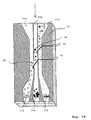
- FIG. One programmable loading microsystem for cells or particles is shown in FIG.
- the centrifugation channel in divided three parts 31a, 31b, 31c.
- Openings 32, through the electrodes 33 again pass the top and bottom of the channel.
- the openings are adapted to the particle size (typically 5 to 20 times larger than the diameter).
- the chemical change or loading of the particles serve.
- the Particles inserted in a channel part (here, for example, 31c).
- the particles pass through the centrifugation (for example, first the black, then the light) to the electrodes 33 and so can automatically over the electric field barriers transferred through the openings 32 in the neighboring solutions become.
- microsystems can have openings (tributaries, flows, outflows), which can be closed, so that the particles after the Centrifugation or before easily removed or inserted can.
- microelectrode elements holding electrodes for particles, micro-cage cages, etc.
- those for the dielectrophoretic influence of particles are known per se and in conventional microsystems, which work with flowing liquids are used. Due to the interaction of the gravitational or centrifugal forces with the dielectrophoretic forces that is Method an electrically controlled or active Centrifugation.
- combinations with the impact optical forces (laser tweezer), magnetic forces (Action on magnetic particles) or mechanical forces be provided in the form of ultrasonic forces.
- Areas of application are in particular: Cell separation / fractionation, cell sorting, cell loading (molecular, nanoparticles, beads), cell loading (molecular), cell permeation (so-called electroporation), cell fusion (so-called electrofusion), cell pair formation, and cell aggregation.
- the method is not limited to certain solution or suspension liquids limited. It is advantageous if the Viscosity of the liquid contained in the microsystem known is. With known viscosity, the speed can be adjusted a certain particle velocity on the Basis of table values or by a program algorithm determine. Alternatively, it is also possible to use the actual Speed of the particles in the microsystem during centrifugation (e.g., with an optical sensor) and the speed for setting a specific particle velocity to regulate. It can be provided that in different subregions of the channel structures, e.g. in parallel Leaky channels, which only have one opening to each other connected, liquids with different viscosities are included. In this case, however, viscosities are preferred, which ensures that the diffusion of the Liquids through the opening over the centrifugation period is relatively small or negligible.
- the process can be modified accordingly be implemented by particles optionally on the Rotary axis facing away from the microsystem are introduced and under the effect of buoyancy or under combined action the buoyancy and centrifugal forces to the other end of the Migrate microsystems.
- the microsystem is application dependent in relation to the Channel structure and the orientation of the electrode devices customized.
- the channel cross dimensions are usually essential larger than the diameter of the individual particles. This will advantageously avoided clogging of the channels. are only to manipulate particles with particularly small dimensions (e.g., bacteria or viruses or cell organelles), so the channel dimensions can be reduced accordingly, e.g. on amounts below 10 ⁇ m.
- the method is implemented with a microsystem that closed at least on one side.
- the closed end can be a closed channel end, a closed collecting zoom or even a closed cavity in the microsystem.
- at Particle manipulation essentially takes place no fluid movement towards the closed end. This means, especially in the realization of collection zones or cavities at the closed end, that these as the whole Microsystem at the beginning of the particle manipulation with the solution or suspension is filled for the particles.
- the speed of the centrifuge briefly increase, so as to replace the cohesive particles and keep moving.
Description
- Fign. 1a bis 1d:
- schematische Perspektivansichten einer Kanalstruktur mit Mikroelektroden zur Erzeugung von Feldbarrieren in einem Mikrokanal und Beispiele erfindungsgemäß gekrümmter Bezugsflächen;
- Fig. 2:
- eine schematische Draufsicht auf bandförmige, gekrümmte Mikroelektroden;
- Fig. 3:
- eine schematische Draufsicht auf eine abgewandelte Gestaltung bandförmiger, gekrümmter Mikroelektroden;
- Fign. 4a bis 4c:
- schematische Ansichten zur Illustration von Sortierelektroden zur Teilchensortierung;
- Fign. 5a und 5b:
- schematische Ansichten von Mikroelektroden zur Erzeugung von Feldgradienten;
- Fign. 6a bis 6e:
- schematische Ansichten bandförmiger Fangelektroden;
- Fign. 7a bis 7c:
- weitere Fangelektroden;
- Fig. 8:
- eine Draufsicht auf verschiedene Elektrodenanordnungen zur Erzeugung von gekrümmten Feldbarrieren;
- Fig. 9:
- eine schematische Ansicht einer Elektrodenanordnung an Seitenwänden eines Kanals;
- Fign. 10 bis 12:
- verschiedene dreidimensionaler Elektrodenanordnungen;
- Fig. 13:
- eine schematische Draufsicht auf eine segmentierte Elektrodenanordnung; und
- Fign. 14 bis 16
- Beispiele mit einem Mikrosystem mit Zentrifugal- und/oder Gravitationsantrieb der Teilchenbe wegung.
| Breite | einige 10 um bis zu einigen mm (typischerweise: 200 - 400 µm) |
| Länge | einige mm bis zu einigen cm (typischerweise: 20 - 50 mm) |
| Höhe | einige µm bis zu einigen 100 µm (typischerweise: 50 µm) |
Zelltrennung/-fraktionierung, Zellsortierung, Zellbeladung (molekular, Nanoteilchen, Beads), Zellentladung (molekular), Zellpermeation (sog. Elektroporation), Zellfusion (sog. Elektrofusion), Zellpärchenbildung, und Zellaggregatbildung.
Claims (13)
- Mikrosystem (20), das zur dielektrophoretischen Manipulierung von Teilchen (30, 30a, 30b) in einer Suspensionsflüssigkeit in einem Kanal (21, 211, 212) eingerichtet ist und eine Elektrodenanordnung (10) mit mindestens einer Mikroelekrode (11, 11a-e, 12, 41a-f, 47, 51a, 51b, 511b, 512b,61a-e, 612a, 71a, 71b, 711a) auf einer seitlichen Wand (21a, 21b, 23) des Kanals zur Erzeugung einer Feldbarriere enthält, die den Kanal zumindest teilweise durchsetzt,
dadurch gekennzeichnet, dass
die Mikroelektrode in Bezug auf die Strömungsrichtung im Kanal einen vorbestimmten stetigen Krümmungsverlauf besitzt oder aus einer Vielzahl jeweils gerader Elektrodenabschnitte mit vorbestimmten Winkeln in Bezug auf die Strömungsrichtung besteht, so dass die Feldbarriere einen vorbestimmten Krümmungsverlauf relativ zur Strömungsrichtung besitzt. - Mikrosystem gemäß Anspruch 1, in dem die Elektrodenanordnung mindestens zwei an gegenüberliegenden Kanalwänden angebrachte Mikroelektroden (11, 12) gleicher Gestalt und Ausrichtung umfasst, die jeweils die Form eines gekrümmten Bandes besitzen.
- Mikrosystem gemäß Anspruch 2, in dem die Mikroelektroden (11a-e, 41a-f) in Abhängigkeit vom Strömungsprofil so gekrümmt sind, dass in jedem Abschnitt der Feldbarriere der Mikroelektrode die auf ein Teilchen wirkende, aus Polarisations- und Strömungskräften resultierende Kraft in einen Bereich weist, der in Bezug auf die Strömungsrichtung vor der Mikroelektrode gelegen ist.
- Mikrosystem gemäß Anspruch 3, in dem vier Mikroelektroden als Fokussierelektroden (11a-e) zur Bildung eines Partikeltrichters angeordnet sind.
- Mikrosystem gemäß Anspruch 2, in dem die Mikroelektroden (11a-e, 41a-f) in Abhängigkeit vom Strömungsprofil so gekrümmt sind, dass die auf ein Teilchen wirkende, aus Polarisationsund Strömungskräften resultierende Kraft von einem relativ zur Strömungsrichtung ersten Ende der Mikroelektrode hin zum anderen Ende eine Richtungsänderung durchläuft, die von einer Richtung in einen Bereich in Bezug auf die Strömungsrichtung vor der Mikroelektrode zu einer Richtung in einen Bereich in Bezug auf die Strömungsrichtung nach der Mikroelektrode führt.
- Mikrosystem gemäß Anspruch 5, in dem zwei Mikroelektroden als Sortierelektroden (11a-e, 41a-f) vorgesehen sind, deren Feldbarriere mit dem Strömungsprofil der Suspensionsflüssigkeit im Kanal so zusammenwirkt, dass suspendierte Teilchen mit verschiedenen passiven elektrischen Eigenschaften die Sortierelektroden je nach ihren Eigenschaften auf getrennten Bahnen passieren können.
- Mikrosystem gemäß Anspruch 2, in dem an gegenüberliegenden Kanalwänden mindestens zwei Mikroelektroden (61a-e, 611a-e, 612a, 71a, 71b, 711a) gleicher Gestalt und Ausrichtung vorgesehen sind, die jeweils einen in Strömungsrichtung geschlossenen Winkelabschnitt aufweisen.
- Mikrosystem gemäß Anspruch 7, in dem die Mikroelektroden als Fangelektroden (61a-e, 611a-e, 612a, 71a, 71b, 711a) zusammenwirken.
- Mikrosystem gemäß Anspruch 7 oder 8, in dem eine Gruppe von Fangelektroden (61a-e, 611a-e, 612a, 71a, 71b, 711a) in Kanalquerrichtung angeordnet sind.
- Mikrosystem gemäß einem der vorhergehenden Ansprüche, in dem die Mikroelektroden paarweise jeweils auf den Boden- und Deckflächen des Kanals angeordnet sind.
- Mikrosystem gemäß Anspruch 1, in dem drei Mikroelektroden vorgesehen sind, von denen zwei Mikroelektroden als Fokussierelektroden (41a-d) in Form von zu einer Mittellinie konvergierenden, bandförmigen Elektroden an den Boden- und Deckflächen des Kanals angebracht und eine dritte Mikroelektrode als feldformende Hilfselektrode (47) mit Abstand von den Boden- und Deckflächen in der Mitte des Kanals angeordnet ist.
- Mikrosystem gemäß Anspruch 11, in dem der Kanal (211, 212) durch eine Trennwand (231) in zwei Teilkanäle mit einer Öffnung stromaufwärts in Bezug auf die Hilfselektrode (103) geteilt ist.
- Verwendung eines Mikrosystems gemäß einem der Ansprüche 1 bis 12 zum Ablenken, Sortieren, Sammeln und/oder Formieren von mikroskopisch kleinen Teilchen.
Applications Claiming Priority (9)
| Application Number | Priority Date | Filing Date | Title |
|---|---|---|---|
| DE19828626 | 1998-06-26 | ||
| DE19828626 | 1998-06-26 | ||
| DE19828919 | 1998-06-29 | ||
| DE19828919 | 1998-06-29 | ||
| DE19853658 | 1998-11-20 | ||
| DE1998153658 DE19853658A1 (de) | 1998-11-20 | 1998-11-20 | Verfahren und Vorrichtung zur Manipulation von Partikeln in Mikrosystemen |
| DE19860118 | 1998-12-23 | ||
| DE19860118A DE19860118C1 (de) | 1998-12-23 | 1998-12-23 | Elektrodenanordnungen zur Erzeugung funktioneller Feldbarrieren in Mikrosystemen |
| PCT/EP1999/004470 WO2000000293A1 (de) | 1998-06-26 | 1999-06-28 | Elektrodenanordnungen zur erzeugung funktioneller feldbarrieren in mikrosystemen |
Publications (2)
| Publication Number | Publication Date |
|---|---|
| EP1089823A1 EP1089823A1 (de) | 2001-04-11 |
| EP1089823B1 true EP1089823B1 (de) | 2003-11-12 |
Family
ID=27438824
Family Applications (1)
| Application Number | Title | Priority Date | Filing Date |
|---|---|---|---|
| EP99929320A Expired - Lifetime EP1089823B1 (de) | 1998-06-26 | 1999-06-28 | Elektrodenanordnungen zur erzeugung funktioneller feldbarrieren in mikrosystemen |
Country Status (6)
| Country | Link |
|---|---|
| US (1) | US7070684B1 (de) |
| EP (1) | EP1089823B1 (de) |
| JP (1) | JP2002519176A (de) |
| AT (1) | ATE253983T1 (de) |
| DE (1) | DE59907733D1 (de) |
| WO (1) | WO2000000293A1 (de) |
Families Citing this family (22)
| Publication number | Priority date | Publication date | Assignee | Title |
|---|---|---|---|---|
| JP4587112B2 (ja) * | 2000-04-13 | 2010-11-24 | 和光純薬工業株式会社 | 誘電泳動装置及び物質の分離方法 |
| JP4671084B2 (ja) * | 2000-12-08 | 2011-04-13 | 和光純薬工業株式会社 | 誘電泳動装置用電極、その製法及び誘電泳動装置並びに該電極を使用する物質の分離方法及び検出方法 |
| EP1806180A1 (de) * | 2001-05-02 | 2007-07-11 | Applera Corporation | Konzentration und Reinigung von Analyten mittels elektrischer Felder |
| GB2375399A (en) * | 2001-05-11 | 2002-11-13 | Suisse Electronique Microtech | Microfluidic system for the manipulation and concentration of particles suspended in fluid |
| JP3695431B2 (ja) * | 2001-08-03 | 2005-09-14 | 日本電気株式会社 | 分離装置および分離装置の製造方法 |
| JP4779261B2 (ja) * | 2001-08-30 | 2011-09-28 | パナソニック株式会社 | 微粒子分離方法、微粒子分離装置、およびセンサ |
| GB0129374D0 (en) * | 2001-12-07 | 2002-01-30 | Univ Brunel | Test apparatus |
| DK1335198T3 (da) * | 2002-02-01 | 2004-07-12 | Leister Process Tech | Mikrofluidik-komponent og fremgangsmåde til sortering af partikler i en væske |
| US20050072677A1 (en) * | 2003-02-18 | 2005-04-07 | Board Of Regents, The University Of Texas System | Dielectric particle focusing |
| CN1917959B (zh) * | 2004-02-17 | 2013-03-27 | 纳幕尔杜邦公司 | 磁场和磁场梯度增强的离心固-液分离 |
| FR2876045B1 (fr) * | 2004-10-04 | 2006-11-10 | Commissariat Energie Atomique | Dispositif pour realiser la separation dielectrophoretique de particules contenues dans un fluide |
| US8075771B2 (en) * | 2005-02-17 | 2011-12-13 | E. I. Du Pont De Nemours And Company | Apparatus for magnetic field gradient enhanced centrifugation |
| US8066877B2 (en) | 2005-02-17 | 2011-11-29 | E. I. Du Pont De Nemours And Company | Apparatus for magnetic field and magnetic gradient enhanced filtration |
| DE102005047131A1 (de) * | 2005-09-30 | 2007-04-12 | Evotec Technologies Gmbh | Verfahren und Vorrichtung zur Manipulation von sedimentierenden Partikeln |
| JP2010510803A (ja) * | 2006-12-01 | 2010-04-08 | コーニンクレッカ フィリップス エレクトロニクス エヌ ヴィ | 流体細胞操作装置 |
| WO2008119066A1 (en) * | 2007-03-28 | 2008-10-02 | The Regents Of The University Of California | Single-sided lateral-field and phototransistor-based optoelectronic tweezers |
| US8702945B2 (en) * | 2007-05-18 | 2014-04-22 | University Of Washington | Time-varying flows for microfluidic particle separation |
| US20090050482A1 (en) * | 2007-08-20 | 2009-02-26 | Olympus Corporation | Cell separation device and cell separation method |
| JP5611582B2 (ja) * | 2009-12-25 | 2014-10-22 | 株式会社東芝 | 電気的中性物質の分離方法、及び電気的中性物質の分離装置 |
| US8973613B2 (en) * | 2011-04-27 | 2015-03-10 | Google Inc. | Electrorheological valve |
| US9441753B2 (en) | 2013-04-30 | 2016-09-13 | Boston Dynamics | Printed circuit board electrorheological fluid valve |
| EP4316660A1 (de) * | 2022-08-01 | 2024-02-07 | Vrije Universiteit Brussel | Partikelführungsschiene |
Family Cites Families (17)
| Publication number | Priority date | Publication date | Assignee | Title |
|---|---|---|---|---|
| US3197394A (en) | 1962-01-02 | 1965-07-27 | Pure Oil Co | Apparatus and method for separating polarizable from non-polarizable particles |
| DE1912322C3 (de) | 1969-03-11 | 1974-10-17 | Fa. Andreas Hettich, 7200 Tuttlingen | Gefaßträger für Zentrifugen |
| US4326934A (en) * | 1979-12-31 | 1982-04-27 | Pohl Herbert A | Continuous dielectrophoretic cell classification method |
| DE3317415A1 (de) | 1983-05-13 | 1984-11-15 | Kernforschungsanlage Jülich GmbH, 5170 Jülich | Kammer zur behandlung von zellen im elektrischen feld |
| US4726904A (en) | 1984-12-17 | 1988-02-23 | Senetek P L C | Apparatus and method for the analysis and separation of macroions |
| DE3610303C1 (de) | 1986-03-26 | 1987-02-19 | Schoenert Klaus Prof Dr Ing | Verfahren und Vorrichtungen zur Sortierung paramagnetischer Partikeln im Fein- und Feinstkornbereich in einem magnetischen Starkfeld |
| US4804355A (en) | 1987-11-17 | 1989-02-14 | Utah Bioresearch, Inc. | Apparatus and method for ultrasound enhancement of sedimentation during centrifugation |
| DE8813314U1 (de) | 1988-10-22 | 1989-01-12 | Erno Raumfahrttechnik Gmbh, 2800 Bremen, De | |
| US5489506A (en) * | 1992-10-26 | 1996-02-06 | Biolife Systems, Inc. | Dielectrophoretic cell stream sorter |
| GB9306729D0 (en) * | 1993-03-31 | 1993-05-26 | British Tech Group | Improvements in separators |
| FR2710279B1 (fr) | 1993-09-23 | 1995-11-24 | Armand Ajdari | Perfectionnements aux procédés et dispositifs de séparation des particules contenues dans un fluide. |
| US5565105A (en) | 1993-09-30 | 1996-10-15 | The Johns Hopkins University | Magnetocentrifugation |
| DE19500660B4 (de) | 1994-12-10 | 2007-12-27 | Fraunhofer-Gesellschaft zur Förderung der angewandten Forschung e.V. | Vorrichtung und Verfahren zur Manipulation mikroskopisch kleiner Partikel sowie deren Verwendung |
| US5888370A (en) * | 1996-02-23 | 1999-03-30 | Board Of Regents, The University Of Texas System | Method and apparatus for fractionation using generalized dielectrophoresis and field flow fractionation |
| GB9619093D0 (en) | 1996-09-12 | 1996-10-23 | Scient Generics Ltd | Methods of analysis/separation |
| US5858192A (en) * | 1996-10-18 | 1999-01-12 | Board Of Regents, The University Of Texas System | Method and apparatus for manipulation using spiral electrodes |
| US6368871B1 (en) * | 1997-08-13 | 2002-04-09 | Cepheid | Non-planar microstructures for manipulation of fluid samples |
-
1999
- 1999-06-28 AT AT99929320T patent/ATE253983T1/de not_active IP Right Cessation
- 1999-06-28 DE DE59907733T patent/DE59907733D1/de not_active Expired - Lifetime
- 1999-06-28 JP JP2000556876A patent/JP2002519176A/ja active Pending
- 1999-06-28 WO PCT/EP1999/004470 patent/WO2000000293A1/de active IP Right Grant
- 1999-06-28 US US09/720,275 patent/US7070684B1/en not_active Expired - Fee Related
- 1999-06-28 EP EP99929320A patent/EP1089823B1/de not_active Expired - Lifetime
Also Published As
| Publication number | Publication date |
|---|---|
| EP1089823A1 (de) | 2001-04-11 |
| WO2000000293A9 (de) | 2000-03-16 |
| DE59907733D1 (de) | 2003-12-18 |
| US7070684B1 (en) | 2006-07-04 |
| ATE253983T1 (de) | 2003-11-15 |
| JP2002519176A (ja) | 2002-07-02 |
| WO2000000293A1 (de) | 2000-01-06 |
Similar Documents
| Publication | Publication Date | Title |
|---|---|---|
| EP1089823B1 (de) | Elektrodenanordnungen zur erzeugung funktioneller feldbarrieren in mikrosystemen | |
| EP1089824B1 (de) | Elektrodenanordnung zur dielektrophoretischen partikelablenkung | |
| EP1603678B1 (de) | Verfahren und vorrichtung zur trennung von partikeln in einer flüssigkeitsströmung | |
| EP1069955B1 (de) | Verfahren und vorrichtung zur manipulierung von mikropartikeln in fluidströmungen | |
| EP1335198B1 (de) | Mikrofluidisches Bauelement und Verfahren für die Sortierung von Partikeln in einem Fluid | |
| EP1141264B1 (de) | Mikrosysteme zur zellpermeation und zellfusion | |
| EP1092144A1 (de) | Verfahren und vorrichtung zur manipulation von partikeln in mikrosystemen | |
| DE60221240T2 (de) | Konzentration und reinigung von analyten mit elektrischen feldern | |
| EP1140343B1 (de) | Verfahren und vorrichtung zur konvektiven bewegung von flüssigkeiten in mikrosystemen | |
| EP1973661A1 (de) | Elektrischer feldkäfig und zugehöriges betriebsverfahren | |
| EP1565266B1 (de) | Fluidisches mikrosystem und verfahren mit feldformenden passivierungsschichten auf mikroelektroden | |
| DE19860118C1 (de) | Elektrodenanordnungen zur Erzeugung funktioneller Feldbarrieren in Mikrosystemen | |
| EP1525449A1 (de) | Impedanzmessung in einem fluidischen mikrosystem | |
| EP1253977A1 (de) | Verfahren und vorrichtung zur abführung suspendierter mikropartikel aus einem fluidischen mikrosystem | |
| EP0946709A1 (de) | Elektrodenanordnung für feldkäfige | |
| DE102005012128A1 (de) | Mikrofluidisches System und zugehöriges Ansteuerverfahren | |
| EP1744831B8 (de) | Verfahren und vorrichtung zur sammlung von suspendierten partikeln | |
| DE10320869A1 (de) | Verfahren und Vorrichtungen zur Flüssigkeitsbehandlung suspendierter Partikel | |
| DE19860117A1 (de) | Elektrodenanordnung zur dielektrophoretischen Partikelablenkung | |
| DE10117771A1 (de) | Verfahren und Vorrichtung zur Manipulation kleiner Flüssigkeitsmengen und/oder darin enthaltener Teilchen | |
| DE102018210993A1 (de) | Vorrichtung zum simultanen dielektrophoretischen Einfang von mehreren Teilchen verschiedener Art | |
| DE19853658A1 (de) | Verfahren und Vorrichtung zur Manipulation von Partikeln in Mikrosystemen |
Legal Events
| Date | Code | Title | Description |
|---|---|---|---|
| PUAI | Public reference made under article 153(3) epc to a published international application that has entered the european phase |
Free format text: ORIGINAL CODE: 0009012 |
|
| 17P | Request for examination filed |
Effective date: 20001213 |
|
| AK | Designated contracting states |
Kind code of ref document: A1 Designated state(s): AT BE CH CY DE DK ES FI FR GB GR IE IT LI LU MC NL PT SE |
|
| RAP1 | Party data changed (applicant data changed or rights of an application transferred) |
Owner name: EVOTEC OAI AG |
|
| 17Q | First examination report despatched |
Effective date: 20020716 |
|
| GRAH | Despatch of communication of intention to grant a patent |
Free format text: ORIGINAL CODE: EPIDOS IGRA |
|
| GRAS | Grant fee paid |
Free format text: ORIGINAL CODE: EPIDOSNIGR3 |
|
| GRAA | (expected) grant |
Free format text: ORIGINAL CODE: 0009210 |
|
| AK | Designated contracting states |
Kind code of ref document: B1 Designated state(s): AT BE CH CY DE DK ES FI FR GB GR IE IT LI LU MC NL PT SE |
|
| PG25 | Lapsed in a contracting state [announced via postgrant information from national office to epo] |
Ref country code: NL Free format text: LAPSE BECAUSE OF FAILURE TO SUBMIT A TRANSLATION OF THE DESCRIPTION OR TO PAY THE FEE WITHIN THE PRESCRIBED TIME-LIMIT Effective date: 20031112 Ref country code: IT Free format text: LAPSE BECAUSE OF FAILURE TO SUBMIT A TRANSLATION OF THE DESCRIPTION OR TO PAY THE FEE WITHIN THE PRESCRIBED TIME-LIMIT;WARNING: LAPSES OF ITALIAN PATENTS WITH EFFECTIVE DATE BEFORE 2007 MAY HAVE OCCURRED AT ANY TIME BEFORE 2007. THE CORRECT EFFECTIVE DATE MAY BE DIFFERENT FROM THE ONE RECORDED. Effective date: 20031112 Ref country code: FR Free format text: LAPSE BECAUSE OF FAILURE TO SUBMIT A TRANSLATION OF THE DESCRIPTION OR TO PAY THE FEE WITHIN THE PRESCRIBED TIME-LIMIT Effective date: 20031112 Ref country code: FI Free format text: LAPSE BECAUSE OF FAILURE TO SUBMIT A TRANSLATION OF THE DESCRIPTION OR TO PAY THE FEE WITHIN THE PRESCRIBED TIME-LIMIT Effective date: 20031112 Ref country code: ES Free format text: LAPSE BECAUSE OF FAILURE TO SUBMIT A TRANSLATION OF THE DESCRIPTION OR TO PAY THE FEE WITHIN THE PRESCRIBED TIME-LIMIT Effective date: 20031112 Ref country code: CY Free format text: LAPSE BECAUSE OF FAILURE TO SUBMIT A TRANSLATION OF THE DESCRIPTION OR TO PAY THE FEE WITHIN THE PRESCRIBED TIME-LIMIT Effective date: 20031112 |
|
| REG | Reference to a national code |
Ref country code: GB Ref legal event code: FG4D Free format text: NOT ENGLISH |
|
| REG | Reference to a national code |
Ref country code: CH Ref legal event code: EP |
|
| REF | Corresponds to: |
Ref document number: 59907733 Country of ref document: DE Date of ref document: 20031218 Kind code of ref document: P |
|
| REG | Reference to a national code |
Ref country code: IE Ref legal event code: FG4D Free format text: GERMAN |
|
| PG25 | Lapsed in a contracting state [announced via postgrant information from national office to epo] |
Ref country code: SE Free format text: LAPSE BECAUSE OF FAILURE TO SUBMIT A TRANSLATION OF THE DESCRIPTION OR TO PAY THE FEE WITHIN THE PRESCRIBED TIME-LIMIT Effective date: 20040212 Ref country code: GR Free format text: LAPSE BECAUSE OF FAILURE TO SUBMIT A TRANSLATION OF THE DESCRIPTION OR TO PAY THE FEE WITHIN THE PRESCRIBED TIME-LIMIT Effective date: 20040212 Ref country code: DK Free format text: LAPSE BECAUSE OF FAILURE TO SUBMIT A TRANSLATION OF THE DESCRIPTION OR TO PAY THE FEE WITHIN THE PRESCRIBED TIME-LIMIT Effective date: 20040212 |
|
| REG | Reference to a national code |
Ref country code: CH Ref legal event code: NV Representative=s name: R. A. EGLI & CO. PATENTANWAELTE |
|
| GBT | Gb: translation of ep patent filed (gb section 77(6)(a)/1977) |
Effective date: 20040218 |
|
| NLV1 | Nl: lapsed or annulled due to failure to fulfill the requirements of art. 29p and 29m of the patents act | ||
| PG25 | Lapsed in a contracting state [announced via postgrant information from national office to epo] |
Ref country code: LU Free format text: LAPSE BECAUSE OF NON-PAYMENT OF DUE FEES Effective date: 20040628 Ref country code: AT Free format text: LAPSE BECAUSE OF NON-PAYMENT OF DUE FEES Effective date: 20040628 |
|
| PG25 | Lapsed in a contracting state [announced via postgrant information from national office to epo] |
Ref country code: MC Free format text: LAPSE BECAUSE OF NON-PAYMENT OF DUE FEES Effective date: 20040630 Ref country code: BE Free format text: LAPSE BECAUSE OF NON-PAYMENT OF DUE FEES Effective date: 20040630 |
|
| PLBE | No opposition filed within time limit |
Free format text: ORIGINAL CODE: 0009261 |
|
| STAA | Information on the status of an ep patent application or granted ep patent |
Free format text: STATUS: NO OPPOSITION FILED WITHIN TIME LIMIT |
|
| 26N | No opposition filed |
Effective date: 20040813 |
|
| EN | Fr: translation not filed | ||
| BERE | Be: lapsed |
Owner name: *EVOTEC OAI A.G. Effective date: 20040630 |
|
| REG | Reference to a national code |
Ref country code: GB Ref legal event code: 732E |
|
| REG | Reference to a national code |
Ref country code: CH Ref legal event code: PUE Owner name: EVOTEC TECHNOLOGIES GMBH Free format text: EVOTEC OAI AG#SCHNACKENBURGALLEE 114#22525 HAMBURG (DE) -TRANSFER TO- EVOTEC TECHNOLOGIES GMBH#MEROWINGERPLATZ 1A#40225 DUESSELDORF (DE) |
|
| REG | Reference to a national code |
Ref country code: CH Ref legal event code: NV Representative=s name: R. A. EGLI & CO. PATENTANWAELTE |
|
| PG25 | Lapsed in a contracting state [announced via postgrant information from national office to epo] |
Ref country code: PT Free format text: LAPSE BECAUSE OF NON-PAYMENT OF DUE FEES Effective date: 20040412 |
|
| PGFP | Annual fee paid to national office [announced via postgrant information from national office to epo] |
Ref country code: IE Payment date: 20090825 Year of fee payment: 11 |
|
| REG | Reference to a national code |
Ref country code: IE Ref legal event code: MM4A |
|
| PG25 | Lapsed in a contracting state [announced via postgrant information from national office to epo] |
Ref country code: IE Free format text: LAPSE BECAUSE OF NON-PAYMENT OF DUE FEES Effective date: 20100628 |
|
| PGFP | Annual fee paid to national office [announced via postgrant information from national office to epo] |
Ref country code: GB Payment date: 20180627 Year of fee payment: 20 Ref country code: DE Payment date: 20180627 Year of fee payment: 20 |
|
| PGFP | Annual fee paid to national office [announced via postgrant information from national office to epo] |
Ref country code: CH Payment date: 20180704 Year of fee payment: 20 |
|
| REG | Reference to a national code |
Ref country code: DE Ref legal event code: R071 Ref document number: 59907733 Country of ref document: DE |
|
| REG | Reference to a national code |
Ref country code: CH Ref legal event code: PL |
|
| REG | Reference to a national code |
Ref country code: GB Ref legal event code: PE20 Expiry date: 20190627 |
|
| PG25 | Lapsed in a contracting state [announced via postgrant information from national office to epo] |
Ref country code: GB Free format text: LAPSE BECAUSE OF EXPIRATION OF PROTECTION Effective date: 20190627 |