EP1088985A2 - Injektor für eine Brennkraftmaschine mit Direkteinspritzung - Google Patents
Injektor für eine Brennkraftmaschine mit Direkteinspritzung Download PDFInfo
- Publication number
- EP1088985A2 EP1088985A2 EP00121484A EP00121484A EP1088985A2 EP 1088985 A2 EP1088985 A2 EP 1088985A2 EP 00121484 A EP00121484 A EP 00121484A EP 00121484 A EP00121484 A EP 00121484A EP 1088985 A2 EP1088985 A2 EP 1088985A2
- Authority
- EP
- European Patent Office
- Prior art keywords
- injector
- nozzle
- bore
- control piston
- control
- Prior art date
- Legal status (The legal status is an assumption and is not a legal conclusion. Google has not performed a legal analysis and makes no representation as to the accuracy of the status listed.)
- Granted
Links
Images


Classifications
-
- F—MECHANICAL ENGINEERING; LIGHTING; HEATING; WEAPONS; BLASTING
- F02—COMBUSTION ENGINES; HOT-GAS OR COMBUSTION-PRODUCT ENGINE PLANTS
- F02M—SUPPLYING COMBUSTION ENGINES IN GENERAL WITH COMBUSTIBLE MIXTURES OR CONSTITUENTS THEREOF
- F02M47/00—Fuel-injection apparatus operated cyclically with fuel-injection valves actuated by fluid pressure
- F02M47/02—Fuel-injection apparatus operated cyclically with fuel-injection valves actuated by fluid pressure of accumulator-injector type, i.e. having fuel pressure of accumulator tending to open, and fuel pressure in other chamber tending to close, injection valves and having means for periodically releasing that closing pressure
- F02M47/027—Electrically actuated valves draining the chamber to release the closing pressure
-
- F—MECHANICAL ENGINEERING; LIGHTING; HEATING; WEAPONS; BLASTING
- F02—COMBUSTION ENGINES; HOT-GAS OR COMBUSTION-PRODUCT ENGINE PLANTS
- F02M—SUPPLYING COMBUSTION ENGINES IN GENERAL WITH COMBUSTIBLE MIXTURES OR CONSTITUENTS THEREOF
- F02M61/00—Fuel-injectors not provided for in groups F02M39/00 - F02M57/00 or F02M67/00
- F02M61/04—Fuel-injectors not provided for in groups F02M39/00 - F02M57/00 or F02M67/00 having valves, e.g. having a plurality of valves in series
- F02M61/10—Other injectors with elongated valve bodies, i.e. of needle-valve type
- F02M61/12—Other injectors with elongated valve bodies, i.e. of needle-valve type characterised by the provision of guiding or centring means for valve bodies
-
- F—MECHANICAL ENGINEERING; LIGHTING; HEATING; WEAPONS; BLASTING
- F02—COMBUSTION ENGINES; HOT-GAS OR COMBUSTION-PRODUCT ENGINE PLANTS
- F02M—SUPPLYING COMBUSTION ENGINES IN GENERAL WITH COMBUSTIBLE MIXTURES OR CONSTITUENTS THEREOF
- F02M61/00—Fuel-injectors not provided for in groups F02M39/00 - F02M57/00 or F02M67/00
- F02M61/16—Details not provided for in, or of interest apart from, the apparatus of groups F02M61/02 - F02M61/14
- F02M61/168—Assembling; Disassembling; Manufacturing; Adjusting
-
- F—MECHANICAL ENGINEERING; LIGHTING; HEATING; WEAPONS; BLASTING
- F02—COMBUSTION ENGINES; HOT-GAS OR COMBUSTION-PRODUCT ENGINE PLANTS
- F02M—SUPPLYING COMBUSTION ENGINES IN GENERAL WITH COMBUSTIBLE MIXTURES OR CONSTITUENTS THEREOF
- F02M61/00—Fuel-injectors not provided for in groups F02M39/00 - F02M57/00 or F02M67/00
- F02M61/16—Details not provided for in, or of interest apart from, the apparatus of groups F02M61/02 - F02M61/14
- F02M61/20—Closing valves mechanically, e.g. arrangements of springs or weights or permanent magnets; Damping of valve lift
Definitions
- the present invention relates to an injector according to the Preamble of claim 1.
- the fuel is supplied in the control room and in the area of the nozzle needle arranged pressure chamber in parallel.
- the fuel supply hole branches into a fuel supply hole, which in the Control room opens and a fuel supply hole that in the pressure chamber opens at the nozzle needle.
- the branch from the fuel supply hole in the control room and the nozzle room runs in the area of a throttle plate.
- Kick here often problems at the fuel feed bore junction to the control room and the pressure room in the separation area of the throttle plate and injector body, because where the high pressures prevailing there and the very hot ones Special fuel seals (metal seals) are required are.
- the leakage that occurs is in such Injectors returned to the tank. Since the leakage is a high temperature is an additional cooling of the tank necessary.
- the power loss of the pump is very high high because the leakage causes a loss of pressure in the Separation area takes place.
- the branch point mentioned above is omitted and consequently the risk of leakage of Leakage in a parting line.
- the fuel goes straight into the axial bore in the injector body and further along the Nozzle needle for the injection opening. This way it increases the efficiency of the injector.
- an injector 10 is shown.
- the injector 10 includes an injector body 20 that fits into an injector body portion 30 and a nozzle body portion 40 divided is.
- An axial bore runs through both sections 30, 40 50.
- In the injector body 20 is a fuel supply hole 60 formed with a rail (not shown) communicates.
- the fuel supply bore 60 opens out below a control piston 70 in through the injector body 20 extending axial bore 50.
- the control piston 70 is firmly connected to a nozzle needle 80, which passes through the axial bore 50 extends in the injector body 20.
- the Accordingly, fuel passes through the fuel supply hole 60 in the axial bore 50 in the injector body 20. Consequently is the entire axial bore 50 below the control piston 70 in the injector body 20 filled with fuel inside the axial bore 50 into the area of an injection opening 290 arrives.
- a control piston 70 In the control piston 70 is a bore 110 formed from which an inlet throttle 120 and a Inlet throttle 130 open into the control room 100.
- the inlet throttle 120 runs obliquely in the control piston 70 and the Inlet throttle 130 extends axially from bore 110 through the control piston 70.
- a Extension 140 formed on the control chamber 100 facing The end face of the cylindrical control piston 70 is a Extension 140 formed.
- the extension 140, at its center the inlet throttle 120 is the stop for the Control piston 70 and thus for the nozzle needle 80.
- the inlet throttle 130 opens into the area of this extension 140 Control room 100, whereas inlet throttle 120 in one area the end face of the control piston 70 in the control chamber 100 opens, which is in the stop position of the control piston 70 continues in a flow restrictor 150 in the valve 90. It is noted at this point that it is also conceivable, only one or more than two flow restrictors in the control piston 70 to provide.
- the nozzle needle 80 is at rest by a spring 160 a needle seat 170 is biased in the nozzle body portion 40.
- the spring 160 is supported by an adjusting washer 180 a shoulder 190 in the injector body 20.
- the control piston 70 and the needle seat 170 in the nozzle body section 40 is exactly concentric are arranged. This required accurate axial Location of needle seat 170 and spool 70 is in the Embodiments of Figures 1, 2, 5, 6 shown, divided Injector body 20 ensured by centering body 210a, 210b.
- the centering body 210a is in Form of a centering ring in a recess 220 on the outer circumference from injector body portion 30 and nozzle body portion 40 arranged in the contact area of the two body sections 30, 40.
- the centering body 210b on the inner circumference, i.e. in the axial bore 50 of the injector body Arrange 20 so that it is inside ( Figure 2). In both cases, the centering bodies 210a, 210b are below Brought in tension.
- the Centering body 230 is due to the long and slim nozzle needle 80 necessary to get an accurate needle guide and a to ensure accurate operation of the injector 10.
- the centering body 230 is in the outer area via a spring 240 the cylindrical injector body bore 50 is pushed.
- the spring 240 is supported on the nozzle needle side via the ring-shaped one Paragraph 200 on the nozzle needle 80.
- the nozzle needle 80 is in a concentrically arranged bore 250 in Guide body 230a out.
- the guide body 230a can be made of an annular starting material, the is so symmetrically deformed that it is in four places a, b, c, d, A, B, C, D on the nozzle needle 80 and on the axial bore 50 is present. After the deformation and one The hardening process is the guide body 230a on its outer circumference A, B, C, D and concentric on the inner surfaces a, b, c, d ground to size. By providing a slight Press fit between the centering body 230a and the nozzle body section 40, the need for the spring 240 can be eliminated.
- the centering body 230b can be made of an angular starting material be made. After the centering body has hardened 230b is just a grinding of the outer X and inner Y diameter necessary.
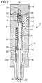
- the embodiment of the injector 10 according to FIG. 2 differs compared to that of Figure 1 only by the implementation of the power transmission from the nozzle spring 160 the nozzle needle 80. This takes place via a spring ring 260, which is arranged in a groove 270 in the nozzle needle 80. A spring plate 280 is slid over the spring ring 260 prevent the spring ring 260 from jumping out.
- the guide body 230a, 230b and the spring 240 are in the Embodiment according to Figure 2 for the sake of clarity not shown, but can in this embodiment can of course also be used.
- FIG. 5 shows a further embodiment of the injector 10 shown in a schematic representation. Unlike the Embodiments according to Figures 1 and 2 are the injector body portion 30 and the nozzle body section 40 in one piece educated. This eliminates the need for a centering body between the two sections 30 and 40. It However, the embodiment should not be excluded 5 according to the embodiments 1 and 2 as in the injector body section 30 and nozzle body portion 40 to perform separate injector body 20.
- the nozzle spring biasing the nozzle needle 80 into the needle seat 170 160 is in the embodiment according to FIG Control room 100 arranged. However, as with the Embodiments described above, also Via the bore 110 in the control piston 70 connection with the area below the control piston 70 in which the Fuel is supplied.
- the nozzle spring 160 has one rectangular cross-section. This is the damage volume of the control room 100 is reduced.
- a Filling piece arranged in the control room 100.
- the injector 10 described in FIGS. 1 to 4 operates as follows:
- the control piston is in the starting position according to FIG. 3A 70 in a lower position.
- the nozzle needle is 80 shifted down into the nozzle needle seat 170 and closes the injection opening 290.
- the outlet throttle 150 and an adjoining bore 300 are through the electrically controllable valve 90 closed.
- control room 100 has access to Space below the spool 70 due to the connection the fuel supply bore 60 with the rail under system pressure stands.
- Control chamber 100 is used to initiate an injection by actuating the valve 90 and simultaneously opening the Drain throttle 150 unloaded, i.e. Fuel in the control room 100 flows through the outlet throttle 150 in the valve 90.
- the Control piston 70 shifts due to the now prevailing Pressure difference - pressure in the control room 100 is less than that System pressure below the control piston 70 - upwards. Such as the control piston 70 with the extension 140 the upper stop reached, the inlet throttle 130 is closed.
- the valve 90 is activated again, so that the flow restrictor 150 is closed.
- the control piston 70 moves slightly downwards, the fuel can also flow through the inlet throttle 130 in reach the control room 100 and the control piston moves down faster and pushes the one connected to it Nozzle needle 80 in its needle seat 170, which is the injection opening 290 closes.
- the inlet throttle 120 has one smallest possible flow cross-section, the inlet throttle 130 has a big one in the interest of quick needle closing Flow cross-section.
- the injector is that the nozzle needle 80 and the control piston 70 form a joint production-favored component.
- the Injector 10 is leak-free and consists of only a few parts.
- the design of inlet and outlet throttles at Common Rail systems represent a compromise.
- the described Throttle combination can optimize the throttle cross sections be interpreted. Tax leakage can be a particular advantage during the injection down to a small residual value to be avoided in the form shown as more leak-free Injector all leakage losses are almost eliminated.
Landscapes
- Engineering & Computer Science (AREA)
- Chemical & Material Sciences (AREA)
- Combustion & Propulsion (AREA)
- Mechanical Engineering (AREA)
- General Engineering & Computer Science (AREA)
- Manufacturing & Machinery (AREA)
- Physics & Mathematics (AREA)
- Fluid Mechanics (AREA)
- Fuel-Injection Apparatus (AREA)
Abstract
Description
Claims (10)
- Injektor (10) für eine Brennkraftmaschine mit Direkteinspritzung, umfassend:dadurch gekennzeichnet, daßeinen Injektorkörper (20), welcher einen Injektorkörperabschnitt (30) und einen Düsenkörperabschnitt (40) aufweist, mit einer sich axial erstreckenden Bohrung (50),eine in die axiale Bohrung (50) mündende Kraftstoffzuführbohrung (60) im Injektorkörper (20),einen in der axialen Bohrung (50) verlagerbaren Steuerkolben (70),einen oberhalb des Steuerkolbens (70) angeordneten Steuerraum (100),ein den Steuerraum (100) entlastendes ansteuerbares Ventil (90),eine sich durch die axiale Bohrung (50) erstreckende, mit dem Steuerkolben (70) in Verbindung stehende Düsennadel (80) zum Öffnen und Schließen einer Einspritzöffnung (290), undeine Düsenfeder (160), die die Düsennadel (80) in einen Nadelsitz (170) im Bereich der Einspritzöffnung vorspannt,
die Kraftstoffzuführbohrung (60) in einem Bereich unterhalb des Steuerkolbens (70) in die axiale Bohrung (50) mündet und daß die Zufuhr von Kraftstoff in den Steuerraum (100) aus dem Bereich der axialen Bohrung (50) unterhalb des Steuerkolbens (70) durch eine Bohrung (110) im Steuerkolben (70) erfolgt. - Injektor (10) nach Anspruch 1, dadurch gekennzeichnet, daß der Injektorkörperabschnitt (30) und der Düsenkörperabschnitt (40) als zwei Teile ausgebildet sind.
- Injektor (10) nach einem der Ansprüche 1 oder 2, dadurch gekennzeichnet, daß von der Bohrung (110) im Steuerkolben (70) zwei Zulaufdrosseln in den Steuerraum (100) münden.
- Injektor (10) nach einem der Ansprüche 1 bis 3, dadurch gekennzeichnet, daß der Steuerkolben (70) als Zylinder ausgebildet ist und einen an der dem Steuerraum (100) zugewandten Stirnseite koaxial angeordneten Fortsatz (140) aufweist.
- Injektor (10) nach einem der Ansprüche 1 bis 4, dadurch gekennzeichnet, daß ein Zentrierkörper (210a,210b) zum exakten konzentrischen Anordnen des Steuerkolbens (70) bezüglich des Nadelsitzes (170) im Kontaktbereich des Injektorkörperabschnitts (30) und des Düsenkörperabschnitts (40) vorgesehen ist.
- Injektor (10) nach einem der Ansprüche 1 bis 5, dadurch gekennzeichnet, daß die Kraftübertragung von der Düsenfeder (160) auf die Düsennadel (80) über an der Düsenfeder (160) angeordnete Übertragungsmittel (200;260,270,280) erfolgt.
- Injektor (10) nach einem der Ansprüche 1 bis 6, dadurch gekennzeichnet, daß die Düsenfeder (160) im Steuerraum (100) angeordnet ist.
- Injektor (10) nach einem der Ansprüche 1 bis 7, dadurch gekennzeichnet, daß in der axialen Bohrung (50) ein Führungskörper (230a,230b) für die Düsennadel (80) angeordnet ist.
- Injektor (10) nach Anspruch 8, dadurch gekennzeichnet, daß der Führungskörper (230a) durch Verformung eines rohrförmigen Ausgangsmaterial hergestellt ist.
- Injektor (10) nach Anspruch 8, dadurch gekennzeichnet, daß der Führungskörper (230b) aus einem kantigen Ausgangsmaterial hergestellt ist.
Applications Claiming Priority (2)
| Application Number | Priority Date | Filing Date | Title |
|---|---|---|---|
| DE19946766 | 1999-09-29 | ||
| DE1999146766 DE19946766C2 (de) | 1999-09-29 | 1999-09-29 | Injektor für eine Brennkraftmaschine mit Direkteinspritzung |
Publications (3)
| Publication Number | Publication Date |
|---|---|
| EP1088985A2 true EP1088985A2 (de) | 2001-04-04 |
| EP1088985A3 EP1088985A3 (de) | 2003-11-19 |
| EP1088985B1 EP1088985B1 (de) | 2006-03-22 |
Family
ID=7923774
Family Applications (1)
| Application Number | Title | Priority Date | Filing Date |
|---|---|---|---|
| EP20000121484 Expired - Lifetime EP1088985B1 (de) | 1999-09-29 | 2000-09-29 | Injektor für eine Brennkraftmaschine mit Direkteinspritzung |
Country Status (2)
| Country | Link |
|---|---|
| EP (1) | EP1088985B1 (de) |
| DE (2) | DE19946766C2 (de) |
Cited By (6)
| Publication number | Priority date | Publication date | Assignee | Title |
|---|---|---|---|---|
| WO2003050408A1 (de) * | 2001-12-07 | 2003-06-19 | Robert Bosch Gmbh | Kraftstoffeinspritzeinrichtung für eine brennkraftmaschine |
| EP1422418A1 (de) * | 2002-11-19 | 2004-05-26 | Robert Bosch Gmbh | Kraftstoffeinspritzventil für Brennkraftmaschinen |
| WO2005111407A1 (de) * | 2004-05-14 | 2005-11-24 | Siemens Aktiengesellschaft | Düsenbaugruppe und einspritzventil |
| WO2006012665A1 (de) * | 2004-08-06 | 2006-02-09 | Robert Bosch Gmbh | Vorrichtung zum einspritzen von kraftstoff in den brennraum einer brennkraftmaschine |
| EP1873393A1 (de) * | 2006-06-27 | 2008-01-02 | Robert Bosch Gmbh | Injektor |
| WO2009016004A1 (de) * | 2007-07-31 | 2009-02-05 | Robert Bosch Gmbh | Kraftstoffinjektor mit einer auf dem kegelventilsitz einer düsennadel aufsitzenden zentrierhülse als führung für die düsennadel |
Families Citing this family (5)
| Publication number | Priority date | Publication date | Assignee | Title |
|---|---|---|---|---|
| DE10132450B4 (de) * | 2001-07-04 | 2010-02-11 | Robert Bosch Gmbh | Kraftstoffeinspritzventil für Brennkraftmaschinen |
| DE10154576C1 (de) * | 2001-11-07 | 2003-04-17 | Bosch Gmbh Robert | Kraftstoffinjektor mit düsennaher Magnetventilanordnung |
| DE10205185A1 (de) * | 2002-02-08 | 2003-08-21 | Bosch Gmbh Robert | Kraftstoffeinspritzeinrichtung für eine Brennkraftmaschine |
| DE10240440C1 (de) * | 2002-09-02 | 2003-12-24 | Siemens Ag | Krafstoffinjektor, insbesondere Common-Rail-Dieselinjektor |
| JP3891974B2 (ja) | 2003-10-01 | 2007-03-14 | 株式会社日本自動車部品総合研究所 | 燃料噴射弁 |
Family Cites Families (5)
| Publication number | Priority date | Publication date | Assignee | Title |
|---|---|---|---|---|
| ATE91752T1 (de) * | 1985-12-02 | 1993-08-15 | Marco Alfredo Ganser | Steuereinrichtung fuer elektro-hydraulisch betaetigte kraftstoffeinspritzventile. |
| DE4203343C1 (en) * | 1992-02-06 | 1993-05-19 | Mtu Friedrichshafen Gmbh | IC engine fuel injection nozzle - has combustion chamber facing openings or spray holes coverable by peripheral closure wall parts |
| US5671715A (en) * | 1995-04-27 | 1997-09-30 | Nipon Soken, Inc. | Fuel injection device |
| US5860597A (en) * | 1997-03-24 | 1999-01-19 | Cummins Engine Company, Inc. | Injection rate shaping nozzle assembly for a fuel injector |
| GB9725804D0 (en) * | 1997-12-06 | 1998-02-04 | Lucas Ind Plc | Fuel injector |
-
1999
- 1999-09-29 DE DE1999146766 patent/DE19946766C2/de not_active Expired - Lifetime
-
2000
- 2000-09-29 DE DE50012433T patent/DE50012433D1/de not_active Expired - Lifetime
- 2000-09-29 EP EP20000121484 patent/EP1088985B1/de not_active Expired - Lifetime
Cited By (11)
| Publication number | Priority date | Publication date | Assignee | Title |
|---|---|---|---|---|
| WO2003050408A1 (de) * | 2001-12-07 | 2003-06-19 | Robert Bosch Gmbh | Kraftstoffeinspritzeinrichtung für eine brennkraftmaschine |
| US6976638B2 (en) | 2001-12-07 | 2005-12-20 | Robert Bosch Gmbh | Fuel injection system for an internal combustion engine |
| EP1422418A1 (de) * | 2002-11-19 | 2004-05-26 | Robert Bosch Gmbh | Kraftstoffeinspritzventil für Brennkraftmaschinen |
| WO2005111407A1 (de) * | 2004-05-14 | 2005-11-24 | Siemens Aktiengesellschaft | Düsenbaugruppe und einspritzventil |
| US7934669B2 (en) | 2004-05-14 | 2011-05-03 | Continental Automotive Gmbh | Nozzle assembly and injection valve |
| WO2006012665A1 (de) * | 2004-08-06 | 2006-02-09 | Robert Bosch Gmbh | Vorrichtung zum einspritzen von kraftstoff in den brennraum einer brennkraftmaschine |
| AT500774A1 (de) * | 2004-08-06 | 2006-03-15 | Bosch Gmbh Robert | Vorrichtung zum einspritzen von kraftstoff in den brennraum einer brennkraftmaschine |
| AT500774B1 (de) * | 2004-08-06 | 2006-07-15 | Bosch Gmbh Robert | Vorrichtung zum einspritzen von kraftstoff in den brennraum einer brennkraftmaschine |
| JP2008509311A (ja) * | 2004-08-06 | 2008-03-27 | ロバート ボッシュ ゲーエムベーハー | 内燃機関の燃焼室の中へ燃料を噴射するための装置 |
| EP1873393A1 (de) * | 2006-06-27 | 2008-01-02 | Robert Bosch Gmbh | Injektor |
| WO2009016004A1 (de) * | 2007-07-31 | 2009-02-05 | Robert Bosch Gmbh | Kraftstoffinjektor mit einer auf dem kegelventilsitz einer düsennadel aufsitzenden zentrierhülse als führung für die düsennadel |
Also Published As
| Publication number | Publication date |
|---|---|
| DE19946766C2 (de) | 2001-07-26 |
| EP1088985B1 (de) | 2006-03-22 |
| DE50012433D1 (de) | 2006-05-11 |
| DE19946766A1 (de) | 2001-04-26 |
| EP1088985A3 (de) | 2003-11-19 |
Similar Documents
| Publication | Publication Date | Title |
|---|---|---|
| DE2500644C2 (de) | Kraftstoffeinspritzventil für Brennkraftmaschinen | |
| EP0657643B1 (de) | Kraftstoffeinspritzeinrichtung für Brennkraftmaschinen | |
| EP1636483B1 (de) | Ventil zum steuern von flüssigkeiten | |
| EP2206912B1 (de) | Kraftstoff-Injektor | |
| DE10246974A1 (de) | Kraftstoffeinspritzvorrichtung für eine Brennkraftmaschine | |
| EP3535486A1 (de) | Brennstoffeinspritzventil zum einspritzen eines gasförmigen und/oder flüssigen brennstoffs | |
| EP1088985A2 (de) | Injektor für eine Brennkraftmaschine mit Direkteinspritzung | |
| DE10122256A1 (de) | Kraftstoff-Einspritzvorrichtung für Brennkraftmaschinen, insbesondere Common-Rail-Injektor, sowie Kraftstoffsystem und Brennkraftmaschine | |
| EP2294309B1 (de) | Kraftstoff-injektor | |
| DE19860476A1 (de) | Kraftstoffeinspritzanlage | |
| DE10131953A1 (de) | Steuermodul für einen Injektor eines Speichereinspritzsystems | |
| EP2310662A1 (de) | Kraftstoff-injektor | |
| EP1952011B1 (de) | Kraftstoff-einspritzvorrichtung für eine brennkraftmaschine mit kraftstoff-direkteinspritzung | |
| EP1671029B1 (de) | KRAFTSTOFF-EINSPRITZVORRICHTUNG, INSBESONDERE FüR EINE BRENNKRAFTMASCHINE MIT KRAFTSTOFF-DIREKTEINSPRITZUNG | |
| DE102015226070A1 (de) | Kraftstoffinjektor | |
| EP1671028A1 (de) | Ventil zur steuerung einer verbindung in einem hochdruckfl s sigkeitssystem, insbesondere einer kraftstoffeinspritzeinrichtung f r eine brennkraftmaschine | |
| DE10031570C2 (de) | Leckage reduzierter Hochdruckinjektor | |
| WO2008049668A1 (de) | Injektor zur einspritzung von kraftstoff in brennräume von brennkraftmaschinen | |
| DE10132248C2 (de) | Kraftstoffinjektor mit 2-Wege-Ventilsteuerung | |
| DE102007029793A1 (de) | Kraftstoffinjektor | |
| EP2019198B1 (de) | Injektor | |
| DE102009001003B4 (de) | Brennstoffeinspritzventil | |
| DE19963367B4 (de) | Common-Rail-Injektor | |
| EP2439398A1 (de) | Brennstoffeinspritzventil | |
| DE102018200359A1 (de) | Ventilanordnung zur Gasdruckregelung, Kraftstoffsystem mit Ventilanordnung zur Gasdruckregelung |
Legal Events
| Date | Code | Title | Description |
|---|---|---|---|
| PUAI | Public reference made under article 153(3) epc to a published international application that has entered the european phase |
Free format text: ORIGINAL CODE: 0009012 |
|
| AK | Designated contracting states |
Kind code of ref document: A2 Designated state(s): AT BE CH CY DE DK ES FI FR GB GR IE IT LI LU MC NL PT SE |
|
| AX | Request for extension of the european patent |
Free format text: AL;LT;LV;MK;RO;SI |
|
| PUAL | Search report despatched |
Free format text: ORIGINAL CODE: 0009013 |
|
| AK | Designated contracting states |
Kind code of ref document: A3 Designated state(s): AT BE CH CY DE DK ES FI FR GB GR IE IT LI LU MC NL PT SE |
|
| AX | Request for extension of the european patent |
Extension state: AL LT LV MK RO SI |
|
| RIC1 | Information provided on ipc code assigned before grant |
Ipc: 7F 02M 47/02 A Ipc: 7F 02M 61/12 B Ipc: 7F 02M 61/16 B Ipc: 7F 02M 61/20 B Ipc: 7F 02M 61/10 B |
|
| 17P | Request for examination filed |
Effective date: 20040517 |
|
| AKX | Designation fees paid |
Designated state(s): DE FR GB IT |
|
| 17Q | First examination report despatched |
Effective date: 20040820 |
|
| RIN1 | Information on inventor provided before grant (corrected) |
Inventor name: LIXL, HEINZ Inventor name: FRANK, WILHELM Inventor name: LEWENTZ, GUENTHER Inventor name: KLUEGL, WENDELIN Inventor name: BARANOWSKI, DIRK, DR. Inventor name: AUGUSTIN, ULRICH, DR. Inventor name: SCHMUTZLER, GERD, DR. |
|
| GRAP | Despatch of communication of intention to grant a patent |
Free format text: ORIGINAL CODE: EPIDOSNIGR1 |
|
| GRAS | Grant fee paid |
Free format text: ORIGINAL CODE: EPIDOSNIGR3 |
|
| GRAA | (expected) grant |
Free format text: ORIGINAL CODE: 0009210 |
|
| AK | Designated contracting states |
Kind code of ref document: B1 Designated state(s): DE FR GB IT |
|
| REG | Reference to a national code |
Ref country code: GB Ref legal event code: FG4D Free format text: NOT ENGLISH |
|
| GBT | Gb: translation of ep patent filed (gb section 77(6)(a)/1977) |
Effective date: 20060322 |
|
| REF | Corresponds to: |
Ref document number: 50012433 Country of ref document: DE Date of ref document: 20060511 Kind code of ref document: P |
|
| ET | Fr: translation filed | ||
| PLBE | No opposition filed within time limit |
Free format text: ORIGINAL CODE: 0009261 |
|
| STAA | Information on the status of an ep patent application or granted ep patent |
Free format text: STATUS: NO OPPOSITION FILED WITHIN TIME LIMIT |
|
| 26N | No opposition filed |
Effective date: 20061227 |
|
| REG | Reference to a national code |
Ref country code: FR Ref legal event code: TP |
|
| REG | Reference to a national code |
Ref country code: GB Ref legal event code: 732E Free format text: REGISTERED BETWEEN 20110825 AND 20110831 |
|
| PGFP | Annual fee paid to national office [announced via postgrant information from national office to epo] |
Ref country code: GB Payment date: 20120920 Year of fee payment: 13 |
|
| GBPC | Gb: european patent ceased through non-payment of renewal fee |
Effective date: 20130929 |
|
| PG25 | Lapsed in a contracting state [announced via postgrant information from national office to epo] |
Ref country code: GB Free format text: LAPSE BECAUSE OF NON-PAYMENT OF DUE FEES Effective date: 20130929 |
|
| PGFP | Annual fee paid to national office [announced via postgrant information from national office to epo] |
Ref country code: IT Payment date: 20140929 Year of fee payment: 15 |
|
| PG25 | Lapsed in a contracting state [announced via postgrant information from national office to epo] |
Ref country code: IT Free format text: LAPSE BECAUSE OF NON-PAYMENT OF DUE FEES Effective date: 20150929 |
|
| REG | Reference to a national code |
Ref country code: FR Ref legal event code: PLFP Year of fee payment: 17 |
|
| REG | Reference to a national code |
Ref country code: FR Ref legal event code: PLFP Year of fee payment: 18 |
|
| REG | Reference to a national code |
Ref country code: FR Ref legal event code: PLFP Year of fee payment: 19 |
|
| PGFP | Annual fee paid to national office [announced via postgrant information from national office to epo] |
Ref country code: FR Payment date: 20180924 Year of fee payment: 19 |
|
| PGFP | Annual fee paid to national office [announced via postgrant information from national office to epo] |
Ref country code: DE Payment date: 20180930 Year of fee payment: 19 |
|
| REG | Reference to a national code |
Ref country code: DE Ref legal event code: R119 Ref document number: 50012433 Country of ref document: DE |
|
| PG25 | Lapsed in a contracting state [announced via postgrant information from national office to epo] |
Ref country code: DE Free format text: LAPSE BECAUSE OF NON-PAYMENT OF DUE FEES Effective date: 20200401 |
|
| PG25 | Lapsed in a contracting state [announced via postgrant information from national office to epo] |
Ref country code: FR Free format text: LAPSE BECAUSE OF NON-PAYMENT OF DUE FEES Effective date: 20190930 |