EP1087640A2 - Anwesenheit- und/oder Grössetopferkennung - Google Patents
Anwesenheit- und/oder Grössetopferkennung Download PDFInfo
- Publication number
- EP1087640A2 EP1087640A2 EP00119241A EP00119241A EP1087640A2 EP 1087640 A2 EP1087640 A2 EP 1087640A2 EP 00119241 A EP00119241 A EP 00119241A EP 00119241 A EP00119241 A EP 00119241A EP 1087640 A2 EP1087640 A2 EP 1087640A2
- Authority
- EP
- European Patent Office
- Prior art keywords
- heating element
- hotplate
- resistance heating
- resonant circuit
- cooking vessel
- Prior art date
- Legal status (The legal status is an assumption and is not a legal conclusion. Google has not performed a legal analysis and makes no representation as to the accuracy of the status listed.)
- Granted
Links
Images

Classifications
-
- H—ELECTRICITY
- H05—ELECTRIC TECHNIQUES NOT OTHERWISE PROVIDED FOR
- H05B—ELECTRIC HEATING; ELECTRIC LIGHT SOURCES NOT OTHERWISE PROVIDED FOR; CIRCUIT ARRANGEMENTS FOR ELECTRIC LIGHT SOURCES, IN GENERAL
- H05B3/00—Ohmic-resistance heating
- H05B3/68—Heating arrangements specially adapted for cooking plates or analogous hot-plates
- H05B3/74—Non-metallic plates, e.g. vitroceramic, ceramic or glassceramic hobs, also including power or control circuits
- H05B3/746—Protection, e.g. overheat cutoff, hot plate indicator
-
- H—ELECTRICITY
- H05—ELECTRIC TECHNIQUES NOT OTHERWISE PROVIDED FOR
- H05B—ELECTRIC HEATING; ELECTRIC LIGHT SOURCES NOT OTHERWISE PROVIDED FOR; CIRCUIT ARRANGEMENTS FOR ELECTRIC LIGHT SOURCES, IN GENERAL
- H05B2213/00—Aspects relating both to resistive heating and to induction heating, covered by H05B3/00 and H05B6/00
- H05B2213/05—Heating plates with pan detection means
Definitions
- the invention relates to a device for detecting the presence and / or the size of a cooking vessel on an electrically heated hotplate after Preamble of claim 1.
- DE 196 46 826 A1 discloses a pot detection in which capacitive Sensors are used, which are formed by several electrodes are also located between the heating conductor and the hotplate and with which an electrical one Resonant circuit is operated. When placing a saucepan on the hotplate the capacitance of these sensors changes and thus the resonance frequency of the resonant circuit.
- pot detection Sensors necessary which are in the hob or between the heating conductor and Hotplate are arranged. These sensors must be designed so that they tolerate the high temperatures in the cooking zone. In addition, measures need to be taken be taken that these sensors the electrical insulation system Do not disturb the heating pan. Pot detection with such is also suitable Sensors not for use with hotplates, on the underside of which electrical resistance heating (via an insulating layer) is applied directly without that an air gap is created in which these sensors are housed could.
- the present invention The task is to implement a simple pot detection, which does not have the disadvantages mentioned above.
- the resistance heating element itself as a capacitive sensor for the pan detection is an additional sensor, which in the system hotplate resistance heating should be accommodated, not necessary. So is an impairment of the electrical insulation system of the heating pot excluded from the outset. In addition, there is also an air gap between the heating element and hot plate not necessary, and the heating element can be in direct Be brought into contact with the hotplate. In addition, the effort for the attachment and wiring of an additional pan detection sensor.
- the invention is preferably designed such that the capacitance of the resistance heating element against a reference potential, preferably against earth, in an electrical resonant circuit is connected that the resonance frequency of this Resonant circuit can be detected by an evaluation unit and so that the presence and / or the size of a cooking vessel can be determined on the hotplate.
- the resistance heating element is preferably via electrical switching means, preferably Chokes, connected to the heating voltage supply and another electrical switching means, preferably an isolating capacitor, in the Resonant circuit switched.
- the resonant circuit includes the resistance heating element, the separation capacitor, an inductive element, preferably a coil, and the reference potential.
- a capacitor is connected between the electrical connections of the resistance heating element a capacitor is connected.
- the heating element forming the corresponding heating circuit in each case is used as a capacitive sensor for pot detection.
- the hotplate is made of ceramic or glass ceramic there is that the resistance heating element is a radiant heater, a foil heating element or is a heating layer or heating track applied to a carrier and that the resistance heating element has line windings or a flat ribbon.
- the value or the change in the resonant frequency of the resonant circuit is the size of a standing on the hotplate or the degree of coverage of the The cooking plate can be recognized by the evaluation unit through a cooking vessel.
- the invention relates to a device for pot detection, with which it is not only possible to determine whether a cooking vessel is on the hotplate stands or not, but also how much of the surface of the hob of one Cooking vessel is covered, whether a large or a small cooking vessel on the hotplate stands and whether it stands on it in the middle or laterally.
- a device for pot detection has an electrically heated one Resistance heating element 1 on the hotplate (FIG. 1). This is over two Lines 2, 3 to an electrical heating voltage supply with 230 volt alternating current connected. In lines 2, 3 there are two chokes DR1 and DR2 switched. These have one for the low-frequency heating voltage (50 or 60 Hz) low impedance, so the heating current can flow almost unhindered.
- a coil in the branch point 4 via an isolating capacitor CN L connected, which on the other hand is connected to the housing 5 and to earth is.
- the resistance heating element 1 or its capacity to the grounded Housing 5, the separating capacitor CN, the coil L and earth a resonant circuit.
- the isolating capacitor CN has a very high impedance for low frequencies, a very low one for high frequencies. In doing so, he prevents the low-frequency 230 volt supply voltage is short-circuited to earth. On the other hand, it lets high-frequency currents, such as occur in such resonant circuits, happen almost unhindered. Thus, the separation capacitor CN separates the Resonant circuit effective from the heating circuit.
- the chokes DR1 and DR2 have for the high frequencies of the resonant circuit a high impedance so that these high frequencies do not get into the power grid can.
- a capacitor CP is connected on the side of the chokes DR1 and DR2. This in turn has a very high impedance for the low-frequency supply voltage, do not let the heating current through; however, for high frequencies (i.e. for the resonant circuit) has a very low impedance, this leaves it unimpeded by.
- the interposition of the capacitor CP shows that both connections of the resistance heating element 1 for the high frequencies of the resonant circuit are at the same potential and so the entire area of the heating element 1 can be used as a capacitance-forming capacitor area.
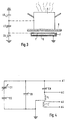
- FIG. 2 shows an equivalent circuit diagram of the resonant circuit from FIG. 1, which - like mentioned above - is separated from the low-frequency heating circuit.
- CH designated the capacity of the heating element 1 against earth. This capacity CH changes - as will be explained in more detail below - when a saucepan 6 is placed on the hotplate With this change in capacitance of CH, the resonance frequency also changes of the resonant circuit.
- FIG. 3 outlines how the capacitance CH of the resistance heating element 1 against earth.
- the heating element 1 is embedded in an insulating layer 7, in the housing 5. There is a glass ceramic plate above the heating element 1 8, on which the saucepan 6 is placed.
- the resistance heating element 1 has on the one hand, a capacitance against the grounded housing 5, that is, against earth. This capacity is called CG.
- the heating element 1 has also has a capacitance CT compared to the saucepan 6.
- the saucepan 6 in turn has also a capacity against earth, which is designated CE.
- the resonance frequency of the resonant circuit can be detected by an evaluation unit. So it can Evaluation unit (not shown) the voltage in the resonant circuit at the connection points A1 or A2 (each against earth) or between points A3 and tap A4. Ports A3 and A4 are one with the two ends Coil L'connected, which is coupled to the coil L of the resonant circuit. Thereby becomes a transmission of the oscillation, i.e. the frequency of the oscillating circuit to the evaluation unit with simultaneous galvanic isolation.
- the signals transmitted in this way are evaluated in the evaluation unit general state of the art.
- the frequency of the resonant circuit can be adjusted be determined by e.g. B. the vibrations in a certain time interval be counted. Differential methods are also conceivable in which is directly recognized when the resonant circuit by setting up, moving or Removing a cooking vessel is out of tune. Using the size of the frequency change of the resonant circuit can be recognized in the evaluation unit is the size of the cooking vessel or how far a cooking vessel is on the hotplate is pushed on or pulled away from the hotplate.
- the respective heating circuit can be used as a separate sensor and so the size of the pot can be determined. It but can also have several, from the respective heating voltage supply Separating capacitors interconnected heating elements to form a capacitive sensor become. In this case, the size of the pot placed determined by the measure of the frequency change in the resonant circuit.
- the evaluation unit sends appropriate signals to a control unit for the hotplate, which then e.g. B. switches off the heating when there is no cooking vessel on the hotplate In the presence of a small pot, only switch on the inner heating circuit when present a large pot switches on both heating circuits or the heating too then turns off when the cooking vessel is too far from the central position on the The hotplate is pushed away.
- the control unit can also be set in this way that they ignore the signals of the evaluation unit of the pan detection and the heating is regulated solely according to the specified setting values.
Landscapes
- Chemical & Material Sciences (AREA)
- Engineering & Computer Science (AREA)
- Ceramic Engineering (AREA)
- Cookers (AREA)
- Induction Heating Cooking Devices (AREA)
- Electric Stoves And Ranges (AREA)
- Geophysics And Detection Of Objects (AREA)
- Traffic Control Systems (AREA)
Abstract
Description
- Figur 1
- einen Schaltplan einer erfindungsgemäßen Topferkennung,
- Figur 2
- ein Ersatzschaltbild des Schwingkreises aus Figur 1,
- Figur 3
- eine Prinzipskizze zur Ermittlung der verschiedenen Kapazitäten und
- Figur 4
- ein erweitertes Ersatzschaltbild des Schwingkreises aus Figur 2.
Claims (10)
- Vorrichtung zur Erkennung der Anwesenheit und/oder der Größe eines Kochgefäßes auf einer elektrisch beheizbaren Kochplatte mit einem unter der Kochplatte befindlichen, an eine elektrische Heizspannungsversorgung angeschlossenen Widerstandsheizelement,
dadurch gekennzeichnet,
daß das Widerstandsheizelement (1) als kapazitiver Sensor zur Topferkennung verwendet ist. - Vorrichtung nach Anspruch 1,
dadurch gekennzeichnet,
daß die Kapazität des Widerstandsheizelementes (1) gegen ein Referenzpotential, vorzugsweise gegen Erde, in einen elektrischen Schwingkreis geschaltet ist, dessen Resonanzfrequenz von einer Auswerteeinheit erfaßbar ist, wodurch die Anwesenheit und/oder die Größe eines Kochgefäßes (6) auf der Kochplatte ermittelbar ist. - Vorrichtung nach Anspruch 1 oder 2,
dadurch gekennzeichnet,
daß das Widerstandsheizelement (1) über elektrische Schaltmittel, vorzugsweise Drosseln (DR1, DR2), an die Heizspannungsversorgung angeschlossen und über ein weiteres elektrisches Schaltmittel, vorzugsweise einen Trennkondensator (CN), in den Schwingkreis geschaltet ist. - Vorrichtung nach einem der Ansprüche 1 bis 3,
dadurch gekennzeichnet,
daß der Schwingkreis das Widerstandsheizelement (1), den Trennkondensator (CN), ein induktives Element, vorzugsweise eine Spule (L), und das Referenzpotential beinhaltet. - Vorrichtung nach einem der vorherigen Ansprüche,
dadurch gekennzeichnet,
daß zwischen die elektrischen Anschlüsse des Widerstandsheizelementes (1) ein Kondensator (CP) geschaltet ist. - Vorrichtung nach einem der vorherigen Ansprüche,
dadurch gekennzeichnet,
daß bei Mehrkreiskochplatten mehrere Schwingkreise verwendbar sind, wobei jeweils das den entsprechenden Heizkreis bildende Heizelement den kapazitiyen Sensor für die Topferkennung bildet. - Vorrichtung nach einem der vorherigen Ansprüche,
dadurch gekennzeichnet,
daß die Kochplatte aus Keramik oder aus Glaskeramik besteht. - Vorrichtung nach einem der vorherigen Ansprüche,
dadurch gekennzeichnet,
daß das Widerstandsheizelement (1) ein Strahlungsheizkörper, ein Folienheizelement oder eine auf einem Träger aufgebrachte Heizschicht bzw. Heizbahn ist. - Vorrichtung nach einem der vorherigen Ansprüche,
dadurch gekennzeichnet,
daß das Widerstandsheizelement (1) Leitungswicklungen oder ein Flachband aufweist. - Vorrichtung nach einem der vorherigen Ansprüche,
dadurch gekennzeichnet,
daß aufgrund des Wertes oder aufgrund der Änderung der Resonanzfrequenz des Schwingkreises die Größe eines auf der Kochplatte stehenden Kochgefäßes (6) bzw. das Ausmaß der Bedeckung der Kochplatte durch ein Kochgefäß (6) von der Auswerteeinheit erkennbar ist.
Applications Claiming Priority (3)
| Application Number | Priority Date | Filing Date | Title |
|---|---|---|---|
| DE19945297A DE19945297A1 (de) | 1999-09-22 | 1999-09-22 | Topferkennung |
| DE19945297 | 1999-09-22 | ||
| US09/666,636 US6259069B1 (en) | 1999-09-22 | 2000-09-21 | Apparatus for detecting the presence of a cooking vessel |
Publications (3)
| Publication Number | Publication Date |
|---|---|
| EP1087640A2 true EP1087640A2 (de) | 2001-03-28 |
| EP1087640A3 EP1087640A3 (de) | 2003-09-17 |
| EP1087640B1 EP1087640B1 (de) | 2006-11-02 |
Family
ID=26055028
Family Applications (1)
| Application Number | Title | Priority Date | Filing Date |
|---|---|---|---|
| EP00119241A Expired - Lifetime EP1087640B1 (de) | 1999-09-22 | 2000-09-06 | Anwesenheit- und/oder Grössetopferkennung |
Country Status (5)
| Country | Link |
|---|---|
| US (1) | US6259069B1 (de) |
| EP (1) | EP1087640B1 (de) |
| AT (1) | ATE344609T1 (de) |
| DE (2) | DE19945297A1 (de) |
| ES (1) | ES2275464T3 (de) |
Cited By (2)
| Publication number | Priority date | Publication date | Assignee | Title |
|---|---|---|---|---|
| WO2007042316A1 (de) * | 2005-10-14 | 2007-04-19 | E.G.O. Elektro-Gerätebau GmbH | Verfahren zur topferkennung und induktionsheizeinrichtung |
| EP2763500A1 (de) * | 2013-01-29 | 2014-08-06 | BSH Bosch und Siemens Hausgeräte GmbH | Kochfeld mit einer Kochfeldplatte und einer Leiterbahn als Flächenbegrenzung für Elektronikkomponenten |
Families Citing this family (25)
| Publication number | Priority date | Publication date | Assignee | Title |
|---|---|---|---|---|
| IT1319292B1 (it) * | 2000-11-08 | 2003-10-10 | Whirlpool Co | Dispositivo per rilevare la collocazione di utensili di cottura su unpiano di cottura ad elementi riscaldanti discreti e distribuiti. |
| US6583392B2 (en) * | 2000-12-22 | 2003-06-24 | General Electric Company | Apparatus and method for determining properties of a cooktop using ultrasound techniques |
| DE10129175A1 (de) * | 2001-06-12 | 2003-01-09 | Ego Elektro Geraetebau Gmbh | Elektrischer Strahlungsheizkörper mit einem Sensor zur Kochgefäßerkennung |
| US6492627B1 (en) * | 2001-07-26 | 2002-12-10 | Emerson Electric Co. | Heating unit and control system for cooktops having capability to detect presence of a pan and methods of operating same |
| CA2358602A1 (en) * | 2001-10-09 | 2003-04-09 | Norax Canada Inc. | Resonance controlled conductive heating |
| DE10156777B4 (de) * | 2001-11-19 | 2012-08-02 | BSH Bosch und Siemens Hausgeräte GmbH | Verfahren zur Übertragung der Einstellungsdaten einer Kochstelle auf eine andere Kochstelle sowie Gargerät zur Durchführung dieses Verfahrens |
| ITMI20031602A1 (it) * | 2003-08-04 | 2005-02-05 | Whirlpool Co | Piano di cottura a piazzamento casuale con interfaccia utente |
| US20050067399A1 (en) * | 2003-09-30 | 2005-03-31 | Chen-Lung Huang | Safety device of a coffee pot |
| US6834160B1 (en) * | 2003-11-14 | 2004-12-21 | Huang Chen-Lung | Electric heater with a sensor preventing no-water heating |
| FR2895639B1 (fr) * | 2005-12-27 | 2008-02-29 | Brandt Ind Sas | Foyer de cuisson par induction de taille variable |
| US20080153182A1 (en) * | 2006-12-21 | 2008-06-26 | Sokudo Co., Ltd | Method and system to measure and compensate for substrate warpage during thermal processing |
| US20080160462A1 (en) * | 2007-01-03 | 2008-07-03 | Sokudo Co., Ltd. | Method and system for bake plate heat transfer control in track lithography tools |
| KR20080068775A (ko) * | 2007-01-20 | 2008-07-24 | 삼성전자주식회사 | 용기센서와 이를 갖는 발열유닛 및 그 발열유닛을 갖는조리장치와 그 제어방법 |
| JP5145822B2 (ja) * | 2007-08-20 | 2013-02-20 | セイコーエプソン株式会社 | 噴射検査装置、印刷装置及び噴射検査方法 |
| EP2194754A1 (de) | 2008-12-05 | 2010-06-09 | Electrolux Home Products Corporation N.V. | Sensoranordnung für Kochgeschirrdetektion |
| ES2356441B1 (es) * | 2008-12-19 | 2012-03-13 | Bsh Electrodomésticos España, S.A. | Campo de cocción con un inductor, un inversor y un dispositivo de conexión. |
| FI122808B (fi) * | 2009-02-24 | 2012-07-13 | Marimils Oy | Tasoelektrodijärjestelmä |
| ES2362782B1 (es) * | 2009-04-17 | 2012-05-22 | Bsh Electrodomésticos España, S.A. | Campo de cocción con una disposición de detección y procedimiento para accionar un campo de cocción. |
| DE102009020905A1 (de) | 2009-05-12 | 2010-12-09 | Diehl Ako Stiftung & Co. Kg | Kochfeld |
| GB0913704D0 (en) * | 2009-08-05 | 2009-09-16 | Next Row Ltd | Induction heating unit for hair rollers |
| US8699299B2 (en) * | 2010-04-26 | 2014-04-15 | Semiconductor Components Industries, Llc | Self-tuning acoustic measurement system |
| DE102012006847B4 (de) * | 2012-04-04 | 2024-05-29 | Rational Aktiengesellschaft | Gargerät mit Einschuberkennung |
| ITUB20155746A1 (it) * | 2015-11-19 | 2017-05-19 | De Longhi Appliances Srl | Apparato per la cottura di alimenti e relativo metodo di cottura |
| WO2019176110A1 (ja) * | 2018-03-16 | 2019-09-19 | 三菱電機株式会社 | 誘導加熱調理器 |
| GB2593468B (en) * | 2020-03-23 | 2022-04-13 | Equip Line Ltd | An apparatus for heating a pot of food or beverage |
Family Cites Families (11)
| Publication number | Priority date | Publication date | Assignee | Title |
|---|---|---|---|---|
| US4334135A (en) * | 1980-12-22 | 1982-06-08 | General Electric Company | Utensil location sensor for induction surface units |
| DE3720720A1 (de) * | 1987-06-23 | 1989-01-05 | Bosch Siemens Hausgeraete | Energieuebertragung fuer kabellose haushaltgeraete |
| DE3934157C2 (de) * | 1989-10-12 | 1999-01-28 | Bosch Siemens Hausgeraete | Kochmulde |
| DE4004129A1 (de) * | 1990-02-10 | 1991-08-14 | Ego Elektro Blanc & Fischer | Einrichtung zum erkennen eines in einer heizzone eines koch- oder waermegeraetes aufgestellten kochgefaesses |
| IT1260456B (it) * | 1992-01-28 | 1996-04-09 | Whirlpool Italia | Metodo e dispositivo per rilevare a presenza di un corpo per esempio una pentola su un piano di cottura in vetroceramica in corrispondenza di un elemento riscaldante associato a tale piano |
| IT1272028B (it) * | 1993-03-15 | 1997-06-10 | Whirlpool Italia | Dispositivo per rilevare la presenza di un contenitore per alimenti, quale una pentola, una pirofila o similare, su un piano di cottura in vetroceramica. |
| DE4336752C2 (de) * | 1993-10-28 | 1999-06-24 | Aeg Hausgeraete Gmbh | Verfahren zum Zubereiten von Speisen in einem Kochgeschirr auf einem Kochfeld aus Keramik, insbesondere Glaskeramik |
| DE19603845B4 (de) | 1996-02-05 | 2010-07-22 | E.G.O. Elektro-Gerätebau GmbH | Elektrischer Strahlungsheizkörper mit einem aktiven Sensor zur Kochgefäßerkennung |
| DE19646826C5 (de) | 1996-02-22 | 2008-10-16 | AEG Hausgeräte GmbH | Vorrichtung zur Temperaturmessung an Kochstellen |
| DE19643698C2 (de) * | 1996-05-11 | 2000-04-13 | Aeg Hausgeraete Gmbh | Vorrichtung zur Abschirmung von für kapazitive Messungen verwendeten Leiterbahnen eines Kochfeldes |
| GB2321699B (en) * | 1997-01-31 | 1999-11-17 | Ceramaspeed Ltd | Electric heating method |
-
1999
- 1999-09-22 DE DE19945297A patent/DE19945297A1/de not_active Withdrawn
-
2000
- 2000-09-06 ES ES00119241T patent/ES2275464T3/es not_active Expired - Lifetime
- 2000-09-06 AT AT00119241T patent/ATE344609T1/de not_active IP Right Cessation
- 2000-09-06 EP EP00119241A patent/EP1087640B1/de not_active Expired - Lifetime
- 2000-09-06 DE DE50013682T patent/DE50013682D1/de not_active Expired - Lifetime
- 2000-09-21 US US09/666,636 patent/US6259069B1/en not_active Expired - Fee Related
Cited By (2)
| Publication number | Priority date | Publication date | Assignee | Title |
|---|---|---|---|---|
| WO2007042316A1 (de) * | 2005-10-14 | 2007-04-19 | E.G.O. Elektro-Gerätebau GmbH | Verfahren zur topferkennung und induktionsheizeinrichtung |
| EP2763500A1 (de) * | 2013-01-29 | 2014-08-06 | BSH Bosch und Siemens Hausgeräte GmbH | Kochfeld mit einer Kochfeldplatte und einer Leiterbahn als Flächenbegrenzung für Elektronikkomponenten |
Also Published As
| Publication number | Publication date |
|---|---|
| DE19945297A1 (de) | 2001-03-29 |
| ES2275464T3 (es) | 2007-06-16 |
| EP1087640B1 (de) | 2006-11-02 |
| US6259069B1 (en) | 2001-07-10 |
| ATE344609T1 (de) | 2006-11-15 |
| EP1087640A3 (de) | 2003-09-17 |
| DE50013682D1 (de) | 2006-12-14 |
Similar Documents
| Publication | Publication Date | Title |
|---|---|---|
| EP1087640B1 (de) | Anwesenheit- und/oder Grössetopferkennung | |
| DE60028485T2 (de) | Objekterfassungssystem, welches zum Beispiel die Anwesenheit eines metallischen Kochgerätes auf einer nichtmetallischen Kochoberfläche erfasst | |
| DE102011005551B4 (de) | Belegungserkennungsvorrichtung zum Erkennen einer Belegung eines Sitzplatzes eines Kraftfahrzeuges | |
| EP2543233B1 (de) | Kochfeld mit zumindest einer kochzone sowie verfahren zum betreiben eines kochfelds | |
| DE69200342T3 (de) | Induktoranordnung zum Induktionsheizen von Kochgefässen und ihre Steuerungsanlage. | |
| DE102014224749B3 (de) | Temperaturerfassung im Stecker mittels überlagerter Prüffrequenz | |
| DE112016002301B4 (de) | Lenkradgrifferfassungsvorrichtung | |
| EP3637948B1 (de) | Heizvorrichtung und verfahren zur temperaturerfassung an einer heizvorrichtung | |
| EP3066888B1 (de) | Induktionskochfeldvorrichtung | |
| EP0374868A1 (de) | Kochfeld | |
| EP3788388B1 (de) | Sensoreinrichtung und verfahren zur bestimmung einer wechselspannung | |
| EP2506673B1 (de) | Induktionskochfeld | |
| EP4179846A1 (de) | Feststellen von funkenüberschlägen während eines mikrowellen-behandlungsablaufs eines haushalts-mikrowellengeräts | |
| EP3977817B1 (de) | Haushalts-mikrowellengerät mit detektionseinrichtung zur erfassung von mikrowellen-leckagestrahlung | |
| DE10042775A1 (de) | Topferkennung | |
| EP3997961B1 (de) | Haushalts-mikrowellengerät mit modenvariationsvorrichtung | |
| DE19707159C2 (de) | Einrichtung zum induktiven Beheizen von Behältern | |
| EP2741571B1 (de) | Kochfeldvorrichtung | |
| DE10011773A1 (de) | Induktions-Gareinrichtung mit Abschirmeinrichtung | |
| EP4183226A1 (de) | Kochfeldvorrichtung | |
| EP1377136A2 (de) | Vorrichtung zum Betreiben von Entladungslampen | |
| CH300516A (de) | Grillanlage. | |
| EP4215019A1 (de) | Gargerätevorrichtung und verfahren zum betrieb einer gargerätevorrichtung | |
| DE3136218A1 (de) | Mikrowellen-oszillator auf einer substratplatte | |
| DE10129175A1 (de) | Elektrischer Strahlungsheizkörper mit einem Sensor zur Kochgefäßerkennung |
Legal Events
| Date | Code | Title | Description |
|---|---|---|---|
| PUAI | Public reference made under article 153(3) epc to a published international application that has entered the european phase |
Free format text: ORIGINAL CODE: 0009012 |
|
| AK | Designated contracting states |
Kind code of ref document: A2 Designated state(s): AT BE CH CY DE DK ES FI FR GB GR IE IT LI LU MC NL PT SE |
|
| AX | Request for extension of the european patent |
Free format text: AL;LT;LV;MK;RO;SI |
|
| PUAL | Search report despatched |
Free format text: ORIGINAL CODE: 0009013 |
|
| AK | Designated contracting states |
Kind code of ref document: A3 Designated state(s): AT BE CH CY DE DK ES FI FR GB GR IE IT LI LU MC NL PT SE |
|
| AX | Request for extension of the european patent |
Extension state: AL LT LV MK RO SI |
|
| 17P | Request for examination filed |
Effective date: 20040114 |
|
| AKX | Designation fees paid |
Designated state(s): AT BE CH CY DE DK ES FI FR GB GR IE IT LI LU MC NL PT SE |
|
| GRAP | Despatch of communication of intention to grant a patent |
Free format text: ORIGINAL CODE: EPIDOSNIGR1 |
|
| GRAS | Grant fee paid |
Free format text: ORIGINAL CODE: EPIDOSNIGR3 |
|
| GRAA | (expected) grant |
Free format text: ORIGINAL CODE: 0009210 |
|
| AK | Designated contracting states |
Kind code of ref document: B1 Designated state(s): AT BE CH CY DE DK ES FI FR GB GR IE IT LI LU MC NL PT SE |
|
| PG25 | Lapsed in a contracting state [announced via postgrant information from national office to epo] |
Ref country code: NL Free format text: LAPSE BECAUSE OF FAILURE TO SUBMIT A TRANSLATION OF THE DESCRIPTION OR TO PAY THE FEE WITHIN THE PRESCRIBED TIME-LIMIT Effective date: 20061102 Ref country code: IE Free format text: LAPSE BECAUSE OF FAILURE TO SUBMIT A TRANSLATION OF THE DESCRIPTION OR TO PAY THE FEE WITHIN THE PRESCRIBED TIME-LIMIT Effective date: 20061102 Ref country code: FI Free format text: LAPSE BECAUSE OF FAILURE TO SUBMIT A TRANSLATION OF THE DESCRIPTION OR TO PAY THE FEE WITHIN THE PRESCRIBED TIME-LIMIT Effective date: 20061102 |
|
| REG | Reference to a national code |
Ref country code: GB Ref legal event code: FG4D Free format text: NOT ENGLISH |
|
| REG | Reference to a national code |
Ref country code: IE Ref legal event code: FG4D Free format text: LANGUAGE OF EP DOCUMENT: GERMAN |
|
| REG | Reference to a national code |
Ref country code: CH Ref legal event code: EP |
|
| REF | Corresponds to: |
Ref document number: 50013682 Country of ref document: DE Date of ref document: 20061214 Kind code of ref document: P |
|
| PG25 | Lapsed in a contracting state [announced via postgrant information from national office to epo] |
Ref country code: SE Free format text: LAPSE BECAUSE OF FAILURE TO SUBMIT A TRANSLATION OF THE DESCRIPTION OR TO PAY THE FEE WITHIN THE PRESCRIBED TIME-LIMIT Effective date: 20070202 Ref country code: DK Free format text: LAPSE BECAUSE OF FAILURE TO SUBMIT A TRANSLATION OF THE DESCRIPTION OR TO PAY THE FEE WITHIN THE PRESCRIBED TIME-LIMIT Effective date: 20070202 |
|
| PG25 | Lapsed in a contracting state [announced via postgrant information from national office to epo] |
Ref country code: PT Free format text: LAPSE BECAUSE OF FAILURE TO SUBMIT A TRANSLATION OF THE DESCRIPTION OR TO PAY THE FEE WITHIN THE PRESCRIBED TIME-LIMIT Effective date: 20070402 |
|
| NLV1 | Nl: lapsed or annulled due to failure to fulfill the requirements of art. 29p and 29m of the patents act | ||
| ET | Fr: translation filed | ||
| GBV | Gb: ep patent (uk) treated as always having been void in accordance with gb section 77(7)/1977 [no translation filed] |
Effective date: 20061102 |
|
| REG | Reference to a national code |
Ref country code: ES Ref legal event code: FG2A Ref document number: 2275464 Country of ref document: ES Kind code of ref document: T3 |
|
| REG | Reference to a national code |
Ref country code: IE Ref legal event code: FD4D |
|
| PLBE | No opposition filed within time limit |
Free format text: ORIGINAL CODE: 0009261 |
|
| STAA | Information on the status of an ep patent application or granted ep patent |
Free format text: STATUS: NO OPPOSITION FILED WITHIN TIME LIMIT |
|
| 26N | No opposition filed |
Effective date: 20070803 |
|
| PG25 | Lapsed in a contracting state [announced via postgrant information from national office to epo] |
Ref country code: GB Free format text: LAPSE BECAUSE OF FAILURE TO SUBMIT A TRANSLATION OF THE DESCRIPTION OR TO PAY THE FEE WITHIN THE PRESCRIBED TIME-LIMIT Effective date: 20061102 |
|
| BERE | Be: lapsed |
Owner name: DIEHL AKO STIFTUNG & CO. K.G. Effective date: 20070930 |
|
| PG25 | Lapsed in a contracting state [announced via postgrant information from national office to epo] |
Ref country code: GR Free format text: LAPSE BECAUSE OF FAILURE TO SUBMIT A TRANSLATION OF THE DESCRIPTION OR TO PAY THE FEE WITHIN THE PRESCRIBED TIME-LIMIT Effective date: 20070203 Ref country code: MC Free format text: LAPSE BECAUSE OF NON-PAYMENT OF DUE FEES Effective date: 20070930 |
|
| REG | Reference to a national code |
Ref country code: CH Ref legal event code: PL |
|
| PG25 | Lapsed in a contracting state [announced via postgrant information from national office to epo] |
Ref country code: LI Free format text: LAPSE BECAUSE OF NON-PAYMENT OF DUE FEES Effective date: 20070930 Ref country code: CH Free format text: LAPSE BECAUSE OF NON-PAYMENT OF DUE FEES Effective date: 20070930 |
|
| PG25 | Lapsed in a contracting state [announced via postgrant information from national office to epo] |
Ref country code: BE Free format text: LAPSE BECAUSE OF NON-PAYMENT OF DUE FEES Effective date: 20070930 |
|
| PG25 | Lapsed in a contracting state [announced via postgrant information from national office to epo] |
Ref country code: AT Free format text: LAPSE BECAUSE OF NON-PAYMENT OF DUE FEES Effective date: 20070906 |
|
| PG25 | Lapsed in a contracting state [announced via postgrant information from national office to epo] |
Ref country code: LU Free format text: LAPSE BECAUSE OF NON-PAYMENT OF DUE FEES Effective date: 20070906 Ref country code: CY Free format text: LAPSE BECAUSE OF FAILURE TO SUBMIT A TRANSLATION OF THE DESCRIPTION OR TO PAY THE FEE WITHIN THE PRESCRIBED TIME-LIMIT Effective date: 20061102 |
|
| PGFP | Annual fee paid to national office [announced via postgrant information from national office to epo] |
Ref country code: ES Payment date: 20090922 Year of fee payment: 10 |
|
| PGFP | Annual fee paid to national office [announced via postgrant information from national office to epo] |
Ref country code: DE Payment date: 20091118 Year of fee payment: 10 |
|
| PGFP | Annual fee paid to national office [announced via postgrant information from national office to epo] |
Ref country code: IT Payment date: 20090926 Year of fee payment: 10 |
|
| PG25 | Lapsed in a contracting state [announced via postgrant information from national office to epo] |
Ref country code: IT Free format text: LAPSE BECAUSE OF NON-PAYMENT OF DUE FEES Effective date: 20100906 |
|
| REG | Reference to a national code |
Ref country code: FR Ref legal event code: ST Effective date: 20110531 |
|
| REG | Reference to a national code |
Ref country code: DE Ref legal event code: R119 Ref document number: 50013682 Country of ref document: DE Effective date: 20110401 |
|
| PG25 | Lapsed in a contracting state [announced via postgrant information from national office to epo] |
Ref country code: FR Free format text: LAPSE BECAUSE OF NON-PAYMENT OF DUE FEES Effective date: 20100930 Ref country code: DE Free format text: LAPSE BECAUSE OF NON-PAYMENT OF DUE FEES Effective date: 20110401 |
|
| PGFP | Annual fee paid to national office [announced via postgrant information from national office to epo] |
Ref country code: FR Payment date: 20091001 Year of fee payment: 10 |
|
| REG | Reference to a national code |
Ref country code: ES Ref legal event code: FD2A Effective date: 20111019 |
|
| PG25 | Lapsed in a contracting state [announced via postgrant information from national office to epo] |
Ref country code: ES Free format text: LAPSE BECAUSE OF NON-PAYMENT OF DUE FEES Effective date: 20100907 |