EP1087220A2 - Tire inspecting method and apparatus - Google Patents
Tire inspecting method and apparatus Download PDFInfo
- Publication number
- EP1087220A2 EP1087220A2 EP00308347A EP00308347A EP1087220A2 EP 1087220 A2 EP1087220 A2 EP 1087220A2 EP 00308347 A EP00308347 A EP 00308347A EP 00308347 A EP00308347 A EP 00308347A EP 1087220 A2 EP1087220 A2 EP 1087220A2
- Authority
- EP
- European Patent Office
- Prior art keywords
- tire
- center
- mark
- angle
- specific point
- Prior art date
- Legal status (The legal status is an assumption and is not a legal conclusion. Google has not performed a legal analysis and makes no representation as to the accuracy of the status listed.)
- Ceased
Links
Images




Classifications
-
- G—PHYSICS
- G01—MEASURING; TESTING
- G01M—TESTING STATIC OR DYNAMIC BALANCE OF MACHINES OR STRUCTURES; TESTING OF STRUCTURES OR APPARATUS, NOT OTHERWISE PROVIDED FOR
- G01M1/00—Testing static or dynamic balance of machines or structures
- G01M1/02—Details of balancing machines or devices
-
- G—PHYSICS
- G01—MEASURING; TESTING
- G01M—TESTING STATIC OR DYNAMIC BALANCE OF MACHINES OR STRUCTURES; TESTING OF STRUCTURES OR APPARATUS, NOT OTHERWISE PROVIDED FOR
- G01M17/00—Testing of vehicles
- G01M17/007—Wheeled or endless-tracked vehicles
- G01M17/02—Tyres
- G01M17/022—Tyres the tyre co-operating with rotatable rolls
-
- G—PHYSICS
- G01—MEASURING; TESTING
- G01M—TESTING STATIC OR DYNAMIC BALANCE OF MACHINES OR STRUCTURES; TESTING OF STRUCTURES OR APPARATUS, NOT OTHERWISE PROVIDED FOR
- G01M17/00—Testing of vehicles
- G01M17/007—Wheeled or endless-tracked vehicles
- G01M17/02—Tyres
- G01M17/027—Tyres using light, e.g. infrared, ultraviolet or holographic techniques
Definitions
- the present invention provides a tire inspecting method comprising steps of: detecting a mark indicating a reference point of a tire; and detecting automatically a position of a specific point of the tire which forms a rotation direction angle with respect to the reference point detected in the mark detecting step.
- a mark indicating a reference point of a tire is detected in the mark detecting step, and on the basis of the detected information, a position of a specific point is detected as a rotation direction angle with respect to the reference point in the specific point position detecting step.
- an angle in a clockwise direction, between a direction connecting the specific point and a center of the tire, and a direction connecting the mark and the center of the tire is automatically detected. Accordingly, the angles for all of the tires can be inspected without requiring much time and labor, and the obtained angles can be immediately used to improve the tires.
- the image taking means takes an image of a surface of a tire at which a mark is provided, and the detecting means detects a position of a specific point.
- the controller detects a position of the mark based on the information; calculates a first angle in a clockwise direction, between a direction connecting the mark and the center of the tire, and a predetermined direction; calculates a second angle in the clockwise direction, between a direction connecting the detected position of the specific point and the center of the tire, and the predetermined direction; and calculates an angle in the clockwise direction, between the direction connecting the mark and the center of the tire, and the direction connecting the specific point and the center of the tire, by subtracting the first angle from the second angle.
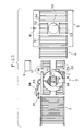
- Fig. 3 is a plan view showing a state in which a tire has been conveyed to a rotating roller portion.
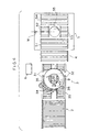
- Fig. 4 is a plan view showing a state in which the tire is rotated at the rotating roller portion.
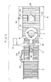
- Fig. 5 is a plan view showing a state in which the tire is conveyed at a carrying conveyer portion.
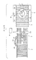
- Fig. 6 is a plan view showing a state in which the tire has been mounted onto a balance light-point position detecting unit.
- Fig. 7 is a side view showing a schematic structure of a balance light-point position detecting apparatus according to another embodiment.
- Fig. 9 is a view for explaining a method for calculating a balance light-point position.
- the present invention is applied to a balance inspecting apparatus for detecting a position of a balance light-point.
- the tire inspecting apparatus 1 is provided with a carrying-in conveyer 2, a rotating roller portion 3, a carrying conveyer portion 4, a balance light-point position detecting unit 5 and a controller 6, sequentially from an upstream side of a conveying direction.
- the rotating roller portion 3 is provided with roller conveyers 31 and 32 which are arranged in parallel so as to be spaced apart from each other.
- the roller conveyers 31 and 32 are inclined with respect to a horizontal direction so that downstream side portions thereof in the conveying direction are lower than upstream side portions thereof in the conveying direction.
- a rotating roller 33 which can move upwardly and downwardly is provided between the roller conveyers 31 and 32.
- a swinging arm 34 to a top end of which a pair of nipping rollers 35 are pivotally supported, is provided at an outer side of the roller conveyer 31.
- the swinging arm 34 can move from a position where the pair of nipping rollers 35 are disposed at the outer side of the roller conveyer 31 to a position where the pair of nipping rollers 35 are disposed in a conveying path of a tire T.
- a bar code reader 38 is suspended above an upstream side from the rotating roller 33 in the conveying direction.
- the carrying conveyer 4 which is continuous with the roller conveyers 31 and 32 is a roller conveyer in which rollers are horizontally arranged, and conveys the tire T to the balance light-point position detecting unit 5.
- the balance light-point position detecting unit 5 is provided with a roller conveyer 51 which is disposed at an upstream side in the conveying direction, roller conveyers 52 and 53 which are disposed at a more downstream side in the conveying direction than the roller conveyer 51 and disposed in parallel and so as to be spaced apart from each other, a roller conveyer 54 which is disposed at a more downstream side in the conveying direction than the roller conveyers 52 and 53, a rim 55 for measuring a balance which is disposed between the roller conveyers 52 and 53 so as to move upwardly and downwardly, a distance detecting sensor 56 which can move around the rim 55 and detects an inclination of the rim 55, a marker 57 which can move around the rim 55 and can also move upwardly and downwardly, a light source 58 which is disposed at a more upstream side in the conveying direction than the rim 55 and emits light upwardly, and a photo sensor 59 which is disposed right above the light source 58.
- the rim 55 is in a cylindrical shape, and an external diameter thereof is substantially the same as an internal diameter of the tire T, so that the tire T does not lower even if the rim 55 is moved upwardly when the rim 55 has been fitted into the tire T. Further, the rim 55 has two extended portions (not shown in the drawings), each of which extends from a point at an inner surface of an upper end portion of the rim 55 to a point which is opposite to said point, and passes through a center of the rim 55, and which portions are orthogonal to each other; and the rim 55 is supported on a supporting axis 55A, which is vertically disposed and can move upwardly and downwardly, at an intersecting portion of the two extended portions disposed at the center of the rim 55. Accordingly, the rim 55 can incline in any direction within 360 degrees.
- the marker 57 is disposed at the roller conveyer 52 side in a reference direction indicated by M.
- the reference direction passes through the center of the rim 55, and is orthogonal to the conveying direction of the tire.
- the controller 6 includes a CPU and a memory, and is electrically connected to each driving device for all of the above-described conveyers (not shown in the drawings), a driving device for the swinging arm 34 (not shown in the drawings), the bar code reader 38, a driving device for the rotating roller 33 (not shown in the drawings), a driving device for the stoppers 36 (not shown in the drawings), a driving device for the supporting axis 55A (not shown in the drawings), a driving device for the distance detecting sensor 56 (not shown in the drawings), the distance detecting sensor 56, a driving device for the marker 57 (not shown in the drawings), the light source 58, and the photo sensor 59.
- a bar code B is affixed to a side surface of the tire T near a bead thereof.
- the bar code B is used as a mark indicating a reference point of the tire.
- the tire T is carried in by the carrying-in conveyer 2 (see Fig. 2), and transferred onto the roller conveyers 31 and 32 at the rotating roller portion 3.
- the rotating roller 33 is retracted downwards, the stoppers 36 are protruded upwards, the nipping rollers 35 are withdrawn outwards due to a swinging of the swinging arm 34, and the rollers of the roller conveyers 31 and 32 are rotated in the same direction.
- the rotating roller 33 is protruded upwards such that the rotating roller 33 is inserted into a hollow portion of the stopped tire T
- the stoppers 36 are retracted such that the tire T is slightly moved until an internal edge of the tire T abuts the rotating roller 33
- the swinging arm 34 is swung and the nipping rollers 35 at a top end of the swinging arm 34 are thereby pivoted such that the tire T is nipped between the nipping rollers 35 and the rotating roller 33 (see Fig. 4).
- the bar code reader 38 is suspended at a predetermined position above the vicinity of the bead of the rotating tire T, and can read the bar code B affixed to the tire T.
- roller conveyers 31 and 32 The driving of roller conveyers 31 and 32 is stopped at the time when the bar code reader 38 has read the bar code B, and the rotation of the tire T is thereby stopped.
- the bar code B is positioned at a more upstream side in the conveying direction than the center of the tire T.
- the tire T is sent onto the carrying conveyer 4, and then, while the bar code B is kept positioned at the more upstream side in the conveying direction than the center of the tire T, the tire T is conveyed onto the balance light-point position detecting unit 5 by the carrying conveyer 4 (see Fig. 5).
- the rim 55 is at a position which is as high as or lower than the roller conveyers 51, 52 and 53.
- the tire T is conveyed along the conveying direction by the roller conveyers 51, 52 and 53.
- the controller 6 stops the roller conveyers 51, 52 and 53 at a predetermined time after receiving detected signals (front end detected signals or back end detected signals) from the photo sensor 59.
- the center of the tire T is coincident with the center of the rim 55, and the rim 55 is moved upwardly so as to fit into the hollow portion of the tire T (see Fig. 6).
- the rim 55 is moved further upwards, the vicinity of the bead at a lower surface of the tire T becomes separated from the roller conveyers 51-54, and the tire T inclines in accordance with its weight balance. At this time, a balance light-point is at a highest position.
- the controller 6 moves the distance detecting sensor 56 along the periphery of the rim 55, and stops the distance detecting sensor 56 at a plurality of predetermined positions on the moving track.
- the distance detecting sensor 56 uses magnetism or light at the time of stopping, and measures a distance between the distance detecting sensor 56 and an upper surface of the tire T by, for example, measuring a time from the time when light is emitted, to the time when the light is reflected by the tire T and returned to the distance detecting sensor 56.
- the measured values are sent to the controller 6, and the controller 6 determines a position of the balance light-point P from the measured values and the corresponding positions where the distance detecting sensor 56 was stopped. Then, the controller 6 calculates an angle a in the clockwise direction, between the direction connecting the balance light-point P and the center of the tire T, and the reference direction M.
- the rim 55 is moved downwardly to a position where the lower surface of the tire T touches the roller conveyers 51-54, and the marker 57 disposed in the reference direction M is moved around the rim 55 by the amount of the angle ⁇ . Then, the marker 57 is moved downwardly so as to mark P showing a balance light-point on the tire T, and thereafter, the marker 57 is returned to the first position. After that, the rim 55 is brought to a position which is as high as or lower than the roller conveyers 51, 52 and 53.
- the controller 6 adds 90 degrees to the calculated angle a, and sends the obtained value, i.e., an angle ⁇ in the clockwise direction, between the direction connecting the bar code B of the tire and the center of the tire, and the direction connecting the balance light-point and the center of the tire, to an unillustrated host computer or the like.
- the position of the balance light-point P of the tire T can be detected as a rotation direction angle ⁇ with respect to the bar code B showing a reference point of the tire T.
- the tire T is carried out by the roller conveyers 52, 53 and 54, and a new tire T is carried in the rotating roller portion 3.
- positions of balance light-points P of all of the tires T can be detected, the amount of detected information which is required to improve the tires T can be obtained in a short time, and the obtained information- can be immediately used to improve the tires.
- the tire inspecting apparatus 1 in the above embodiment detects the angle a by the balance light-point position detecting unit 5 and the controller 6.
- a conventionally known balance device which detects the angle a and marks the detected position, is used as the balance light-point position detecting unit 5, and the controller 6 adds the angle in the clockwise direction, between the direction connecting the center of the tire and the reference point of the tire, and the reference direction, to the angle a detected by the balance device.
- the rim 55 is enabled to rotate and the bar code reader is provided above the rim so as to omit the carrying-in conveyer 2, the rotating roller portion 3 and the carrying conveyer portion 4.
- the tire it is also possible for the tire to be mounted onto the rim 55, and the rim 55 rotated thereafter until the bar code reader has read the bar code, and then the position of the balance light-point P and the angle ⁇ are obtained as described above.
- the above embodiment may be provided with a tire-uniformity measuring device in place of the balance light-point position detecting unit 5.
- the tire is conveyed to the device in the state in which the bar code is positioned at a more upstream side in the conveying direction than the center of the tire, thereafter the tire is mounted onto the rotatable rim in the vertical direction of the tire-uniformity measuring device so that the bar code is disposed at a predetermined position, and then the tire is caused to make one revolution.
- a primary peak (maximum value) of Radial Force Variation (RFV) generated when the tire is rotated is detected by the measuring device, and the position showing the primary peak is measured by an encoder or the like, which is attached to the rim and whose reference is set at the predetermined position. From the results of the encoder, an angle between the direction connecting the bar code B and the center of the tire, and the direction connecting the RFV specific point and the center of the tire, is calculated. Also in this case of the tire-uniformity measuring device, the bar code reader may be provided near the rim so as to omit the carrying-in conveyer 2, the rotating roller portion 3 and the carrying conveyer portion 4.
- RMV Radial Force Variation
- the tire is mounted onto the rim, and the tire is rotated until the bar code has been disposed at the predetermined position corresponding to the bar code reader, and thereafter, the tire is caused to make one more revolution.
- a maximum value of RFV and a position corresponding to the maximum value can be measured by the encoder or the like in which a reference is set at the predetermined position.
- the tire-uniformity measuring device can also measure an angle in the clockwise direction, between the direction connecting the bar code B and the center of the tire, and the direction connecting the maximum value of the radial variation, which value is one of the specific points of the tire, and the center of the tire.
- the present invention can be applied to other detecting devices for detecting specific point positions of tires.
- the balance light-point position detecting device 70 is provided with a CCD camera 76 which is disposed at a predetermined position above the rim 55.
- the CCD camera 76 converts an optical image to electric signals which have a voltage corresponding to a quantity of light of the optical image, and converts the electric signals to image data with an A/D (analog/digital) converter.
- the light source 58 and the photo sensor 59 are disposed at a more upstream side in the conveying direction (direction A) than the roller conveyer 51, and the distance detecting sensor 56 is disposed above the CCD camera 76 and enabled to move upward, downward and around the rim 55.
- the marker 57 is also disposed above the CCD camera 76.
- the controller 6 is electrically connected to each driving device for all of the conveyers (not illustrated), a driving device for the supporting axis 55A (not illustrated), a driving device for the distance detecting sensor 56 (not illustrated), the distance detecting sensor 56, a driving device for the marker 57 (not illustrated), the light source 58, and the photo sensor 59.
- the rim 55 is initially at a position which is as high as or lower than the roller conveyers 51, 52 and 53.
- the tire T which has been conveyed to the balance light-point position detecting device 70 by an unillustrated conveying means, is conveyed along the conveying direction by the roller conveyers 51, 52 and 53.
- the controller 6 stops the roller conveyers 51, 52 and 53 at a predetermined time after receiving detected signals (front end detected signals or back end detected signals) from the photo sensor 59. At this time, the center of the tire T is coincident with the center of the rim 55, and the rim 55 is moved upwardly so as to fit into the hollow portion of the tire T.
- the controller 6 receives the image data from the CCD camera 76 when the tire T is horizontally disposed at a position for assembling the tire T with the rim 55 (at this time, the rim 55 may or may not be fitted to the tire T) and before the balance light-point P is marked.
- the controller 6 compares the image data, and thereby detects the position of the portion, at which the bar code B is affixed, whose image density is different from that of other portions, and calculates an angle ⁇ in the clockwise direction, between the direction connecting the position and the center of the tire, and the reference direction M.
- a rotation direction angle a is calculated in the same manner as the above-described procedure, and the calculated position is marked.
- the controller 6 subtracts the angle ⁇ from the angle ⁇ , and thereby calculates an angle ⁇ in the clockwise direction, between the direction connecting the bar code B of the tire and the center of the tire, and the direction connecting the balance light-point and the center of the tire.
- the angle ⁇ in the clockwise direction, between the direction connecting the bar code B of the tire and the center of the tire, and the direction connecting the balance light-point and the center of the tire can be sequentially and automatically detected for the carried-in tires T without causing the operators any trouble, and thus, time and labor is considerably reduced.
- the angles ⁇ for all of the tires T can be measured, an amount of information which is required to improve the tires T can be obtained in a short time, and the information can be immediately used to improve the tires.
- the bar code B is affixed to a particular position of the tire T, for example, a position which always has a fixed positional relationship with a side-joint portion, if there is a statistical bias on positions of balance light-points P or primary peak positions of RFV, the cause is traced on the basis of the relationship with the side-joint portion, and the obtained information can be used to improve the tires.
- any optically detectable marks other than the bar code B may indicate the reference point of the tire.
Landscapes
- Physics & Mathematics (AREA)
- General Physics & Mathematics (AREA)
- Testing Of Balance (AREA)
- Length Measuring Devices By Optical Means (AREA)
- Tires In General (AREA)
- Length Measuring Devices With Unspecified Measuring Means (AREA)
Abstract
Description
Claims (17)
- A tire inspecting method comprising steps of:detecting a mark indicating a reference point of a tire; anddetecting automatically a position of a specific point of the tire which forms a rotation direction angle with respect to the reference point detected in said mark detecting step.
- A tire inspecting method according to Claim 1, further comprising the steps of:positioning said mark in a predetermined direction from a center of the tire by rotating the tire having said mark and said specific point;detecting a position of said specific point; anddetecting an angle in a clockwise direction, between a direction connecting the detected position of said specific point and the center of the tire, and said predetermined direction.
- A tire inspecting method according to Claim 1, further comprising the steps of:taking an image of a surface of the tire at which said mark is provided;detecting a position of said mark by analyzing image information of the tire whose image has been taken;calculating a first angle in the clockwise direction, between a direction connecting the position of said mark and the center of the tire, and a predetermined direction;detecting a position of said specific point;calculating a second angle in the clockwise direction, between a direction connecting the position of said specific point and the center of the tire, and said predetermined direction; andcalculating an angle in the clockwise direction, between the direction connecting said mark and the center of the tire, and the direction connecting said specific point and the center of the tire, by subtracting said first angle from said second angle.
- A tire inspecting apparatus comprising:a rotating means, which rotates a tire having a specific point and a mark indicating a reference point;a sensor, which detects that said mark has been positioned in a predetermined direction with respect to a center of the tire;a detecting means, which detects a position of said specific point; anda controller, which drives said rotating means; stops the rotation of the tire when said mark has been positioned in said predetermined direction with respect to the center of the tire; causes said detecting means to detect the position of said specific point; and detects an angle in a clockwise direction, between a direction connecting the detected position of said specific point and the center of the tire, and said predetermined direction.
- A tire inspecting apparatus according to Claim 4, wherein said rotating means rotates the tire in a horizontal direction, and further comprises: a conveying means, which conveys the tire, in which said mark has been positioned in the predetermined direction with respect to the center of the tire, to said detecting means along a conveying direction, while said mark is kept positioned in the predetermined direction with respect to the center of the tire.
- A tire inspecting apparatus according to Claim 5, wherein said conveying means comprises: roller conveyers, and a sensor which detects when the tire has passed a predetermined position in said conveying direction.
- A tire inspecting apparatus according to Claim 6, wherein said sensor, which detects when the tire has passed the predetermined position in said conveying direction, comprises: a light source, which emits light toward said predetermined position; and a photo sensor, which detects the light from said light source.
- A tire inspecting apparatus according to Claim 5, wherein said rotating means comprises: a pair of roller conveyers, which are disposed in parallel and driven independently; and a holding means, which holds said tire at a predetermined position.
- A tire inspecting apparatus according to Claim 8, wherein said holding means comprises: stoppers which are disposed between said pair of roller conveyers so as to move upwardly and downwardly; and a swinging arm, which can move from a position where the swinging arm nips the tire with said stoppers, to an outer position in said conveying direction.
- A tire inspecting apparatus according to Claim 4, wherein said mark is a bar code, and said sensor is a bar code reader.
- A tire- inspecting apparatus according to Claim 4, wherein said detecting means comprises: a rim, which can be inclined in any direction within 360 degrees; and a sensor, which detects an inclination of said rim.
- A tire inspecting apparatus according to Claim 11, wherein said sensor, which detects the inclination of said rim, can move around said rim, and measures a distance between said sensor and an upper surface of said tire or said rim.
- A tire inspecting apparatus according to Claim 4, wherein said detecting means comprises: a sensor, which measures a maximum value of Radial Force Variation generated when the tire is rotated; and an encoder, which is attached to said rotating means.
- A tire inspecting apparatus, which detects an angle in a clockwise direction, between a direction connecting a center of the tire, which has a specific point and a mark indicating a reference point, and said specific point, and a direction connecting the center of the tire and said mark, said apparatus comprising:an image taking means, which takes an image of a surface of the tire at which said mark is provided;a detecting means, which detects a position of said specific point; anda controller, which detects a position of said mark by analyzing image information from said image taking means; calculates a first angle in the clockwise direction, between the direction connecting said mark and the center of the tire, and a predetermined direction; causes said detecting means to detect the position of said specific point; calculates a second angle in the clockwise direction, between the direction connecting the detected position of said specific point and the center of the tire, and said predetermined direction; and calculates an angle in the clockwise direction, between the direction connecting said mark and the center of the tire, and the direction connecting said specific point and the center of the tire, by subtracting said first angle from said second angle.
- A tire inspecting apparatus according to Claim 14, wherein said image taking means is a CCD camera.
- A tire inspecting apparatus according to Claim 14, wherein said detecting means comprises: a rim, which can be inclined in any direction within 360 degrees; and a sensor, which detects an inclination of said rim.
- A tire inspecting apparatus according to Claim 14, wherein said detecting means comprises: a rotating means, which rotates the tire; a sensor, which measures a maximum value of Radial Force Variation generated when the tire is rotated; and an encoder, which is attached to said rotating means.
Applications Claiming Priority (2)
| Application Number | Priority Date | Filing Date | Title |
|---|---|---|---|
| JP26869899 | 1999-09-22 | ||
| JP26869899 | 1999-09-22 |
Publications (3)
| Publication Number | Publication Date |
|---|---|
| EP1087220A2 true EP1087220A2 (en) | 2001-03-28 |
| EP1087220A8 EP1087220A8 (en) | 2001-09-19 |
| EP1087220A3 EP1087220A3 (en) | 2003-04-16 |
Family
ID=17462144
Family Applications (1)
| Application Number | Title | Priority Date | Filing Date |
|---|---|---|---|
| EP20000308347 Ceased EP1087220A3 (en) | 1999-09-22 | 2000-09-22 | Tire inspecting method and apparatus |
Country Status (3)
| Country | Link |
|---|---|
| US (1) | US6417918B1 (en) |
| EP (1) | EP1087220A3 (en) |
| JP (1) | JP4540205B2 (en) |
Cited By (7)
| Publication number | Priority date | Publication date | Assignee | Title |
|---|---|---|---|---|
| WO2006024109A1 (en) * | 2004-09-03 | 2006-03-09 | Newsouth Innovations Pty Limited | Rotatable objects and systems and methods for determining the position of at least one sample on a rotatable object |
| WO2015086187A1 (en) * | 2013-12-13 | 2015-06-18 | Continental Reifen Deutschland Gmbh | Method for performing an automated marking of a high point on a vehicle tire |
| WO2015092651A1 (en) | 2013-12-17 | 2015-06-25 | Pirelli Tyre S.P.A. | Method for controlling the quality of a tyre for vehicle wheels |
| CN105021411A (en) * | 2014-04-16 | 2015-11-04 | 株式会社神户制钢所 | Tire testing machine |
| CN110462363A (en) * | 2017-03-28 | 2019-11-15 | 株式会社神户制钢所 | Tire testing method and tire testing device |
| CN113252242A (en) * | 2021-05-07 | 2021-08-13 | 三角轮胎股份有限公司 | Protector for tyre dynamic balance testing station |
| EP4667895A1 (en) * | 2024-06-19 | 2025-12-24 | Continental Reifen Deutschland GmbH | Method and apparatus for identifying sidewall tires and tires |
Families Citing this family (27)
| Publication number | Priority date | Publication date | Assignee | Title |
|---|---|---|---|---|
| US6831996B1 (en) * | 2001-09-24 | 2004-12-14 | Oberg Industries | Method for inspecting an automotive wheel and associated apparatus |
| KR100479556B1 (en) * | 2002-07-15 | 2005-04-06 | 한국타이어 주식회사 | Centering apparatus of tire X-Ray inspection |
| KR100719914B1 (en) | 2005-09-28 | 2007-05-18 | 한국타이어 주식회사 | Finishing tire standard recognition device |
| DE102007038176A1 (en) * | 2007-08-13 | 2009-02-19 | Steinbichler Optotechnik Gmbh | tire testing |
| JP5241315B2 (en) * | 2008-05-13 | 2013-07-17 | 住友ゴム工業株式会社 | TIRE ROTATION BARCODE READING DEVICE, TIRE SORTING DEVICE, AND TIRE ROTATION BARCODE READING METHOD |
| JP5416427B2 (en) * | 2009-02-10 | 2014-02-12 | 住友ゴム工業株式会社 | Estimation system for high-speed tire FV |
| EP2449360B8 (en) * | 2009-06-29 | 2017-08-02 | Compagnie Générale des Etablissements Michelin | System and method for evaluating surface finish of tire retread |
| KR101025291B1 (en) | 2009-12-15 | 2011-03-29 | 한국타이어 주식회사 | Tire Barcode Scanning Device |
| US9038449B2 (en) | 2010-04-16 | 2015-05-26 | Camber Ridge, Llc | Tire testing systems and methods |
| US8474311B2 (en) * | 2011-04-15 | 2013-07-02 | Camber Ridge, Llc | Tire testing systems and methods |
| WO2012088226A1 (en) * | 2010-12-23 | 2012-06-28 | Micro-Poise Measurement Systems, Llc | Tire handling apparatus and method |
| JP5731240B2 (en) * | 2011-03-08 | 2015-06-10 | 大和製衡株式会社 | Tire balance measurement system |
| WO2013040148A2 (en) | 2011-09-13 | 2013-03-21 | Camber Ridge, Llc | Tire testing systems and methods |
| JP6034759B2 (en) * | 2013-06-27 | 2016-11-30 | 株式会社神戸製鋼所 | Marking device |
| KR101543253B1 (en) | 2013-12-23 | 2015-08-11 | 한국타이어 주식회사 | Barcode cognition equipment of tire bead |
| JP5997322B2 (en) * | 2015-06-18 | 2016-09-28 | 株式会社神戸製鋼所 | Conveyor for tire testing machine |
| EP3423802A1 (en) * | 2016-02-29 | 2019-01-09 | Plombco Inc. | Balancing weight application machine and method of use thereof |
| JP6073516B1 (en) * | 2016-04-01 | 2017-02-01 | 株式会社日立パワーソリューションズ | Radiation measuring apparatus and radiation measuring method |
| JP7031106B2 (en) * | 2017-09-25 | 2022-03-08 | 住友ゴム工業株式会社 | Tire inner surface shape measuring device and tire inner surface shape measuring method |
| US11039631B2 (en) | 2017-10-19 | 2021-06-22 | Harold Dail Kimrey, JR. | Compact radio frequency heating of packaged articles |
| WO2019211955A1 (en) | 2018-05-01 | 2019-11-07 | 横浜ゴム株式会社 | Tire production method and device |
| JP7063093B2 (en) * | 2018-05-01 | 2022-05-09 | 横浜ゴム株式会社 | Tire manufacturing information grasping method and equipment |
| DE102018209032A1 (en) * | 2018-06-07 | 2019-12-12 | Continental Reifen Deutschland Gmbh | Apparatus and method for automatically determining the position of the bar code of a tire or green tire and a corresponding computer program, computer program product and a computer-readable data carrier |
| CN110579362A (en) * | 2018-10-31 | 2019-12-17 | 鞍山彩盛机械制造有限公司 | Tire detection and precise brake positioning system and method |
| CN117916077A (en) * | 2021-09-17 | 2024-04-19 | 普利司通美国轮胎运营有限责任公司 | Balance of injected sealant |
| CN117836126A (en) * | 2021-09-17 | 2024-04-05 | 普利司通美国轮胎运营有限责任公司 | Use injected sealants to improve dynamic tire balance |
| FR3136093B3 (en) * | 2022-05-24 | 2024-05-03 | Michelin & Cie | Method and system for recording the coordinates of a visual indication of the uniformity of an identified tire equipped with an RFID chip |
Family Cites Families (24)
| Publication number | Priority date | Publication date | Assignee | Title |
|---|---|---|---|---|
| US3678761A (en) * | 1970-01-12 | 1972-07-25 | Ird Mechanalysis | Method and apparatus for determining unbalance |
| US3877315A (en) * | 1973-06-15 | 1975-04-15 | Fmc Corp | Wheel balancer |
| US3918816A (en) * | 1974-04-22 | 1975-11-11 | Autech Corp | Tire inspection apparatus |
| JPS55138630A (en) * | 1979-04-16 | 1980-10-29 | Yamato Scale Co Ltd | Static unbalance measuring apparatus of tyre |
| US4392745A (en) * | 1981-04-06 | 1983-07-12 | Industrial Holographics, Inc. | Tilt head camera for interferometric analysis of tires |
| JPS5973085A (en) * | 1982-10-21 | 1984-04-25 | 横浜ゴム株式会社 | Reading device for mark for discriminating tire |
| JPS61212742A (en) * | 1985-03-16 | 1986-09-20 | Kobe Steel Ltd | High point marking system for tire uniformity machine |
| JPS61229171A (en) * | 1985-04-04 | 1986-10-13 | Bridgestone Corp | Method and device for reading tire information |
| US4798469A (en) * | 1985-10-02 | 1989-01-17 | Burke Victor B | Noncontact gage system utilizing reflected light |
| JPH01100410A (en) * | 1987-10-14 | 1989-04-18 | Bridgestone Corp | Automatic detector of label position on tire |
| JP2845500B2 (en) * | 1989-07-07 | 1999-01-13 | 株式會社長濱製作所 | Dynamic balance testing machine system |
| JPH0820228B2 (en) * | 1990-01-31 | 1996-03-04 | 住友ゴム工業株式会社 | Method and apparatus for measuring profile of tire outer peripheral surface |
| JPH0756464B2 (en) * | 1990-02-01 | 1995-06-14 | 住友ゴム工業株式会社 | Tire contact shape / contact pressure measuring device |
| JP3088734B2 (en) * | 1990-07-27 | 2000-09-18 | 株式会社バンザイ | Tire-wheel phase matching device |
| JPH04262219A (en) * | 1990-12-27 | 1992-09-17 | Yokohama Rubber Co Ltd:The | Unbalance removing method in dynamic balancer machine |
| JPH0618233A (en) * | 1992-04-17 | 1994-01-25 | Yokohama Rubber Co Ltd:The | Tire inspection method |
| JP3153009B2 (en) * | 1992-07-20 | 2001-04-03 | 東洋ゴム工業株式会社 | Tire white mark inspection device |
| JPH07300222A (en) * | 1994-05-02 | 1995-11-14 | Bridgestone Corp | Method and device for reading mark on tire |
| US5703680A (en) * | 1996-01-16 | 1997-12-30 | The Goodyear Tire & Rubber Company | Method for dynamic interference pattern testing |
| US5883304A (en) * | 1996-08-09 | 1999-03-16 | Bridgestone Corporation | Apparatus for measuring and correcting uniformity of tires |
| JPH11132893A (en) * | 1997-10-31 | 1999-05-21 | Yamato Scale Co Ltd | Automatic eccentricity adjustment device for tire balancer adapter |
| JP3949796B2 (en) * | 1997-11-06 | 2007-07-25 | 株式会社ブリヂストン | Tire shape determination device |
| JP3133726B2 (en) * | 1998-03-06 | 2001-02-13 | 株式会社ブリヂストン | Tire / wheel assembling method, recording medium recording a phase angle calculation program when assembling tire and wheel, tire / wheel assembly |
| US6285195B1 (en) * | 1998-03-16 | 2001-09-04 | David Needle | Time domain reflectometry apparatus and method |
-
2000
- 2000-09-21 US US09/666,833 patent/US6417918B1/en not_active Expired - Lifetime
- 2000-09-22 EP EP20000308347 patent/EP1087220A3/en not_active Ceased
- 2000-09-22 JP JP2000288846A patent/JP4540205B2/en not_active Expired - Fee Related
Cited By (11)
| Publication number | Priority date | Publication date | Assignee | Title |
|---|---|---|---|---|
| WO2006024109A1 (en) * | 2004-09-03 | 2006-03-09 | Newsouth Innovations Pty Limited | Rotatable objects and systems and methods for determining the position of at least one sample on a rotatable object |
| WO2015086187A1 (en) * | 2013-12-13 | 2015-06-18 | Continental Reifen Deutschland Gmbh | Method for performing an automated marking of a high point on a vehicle tire |
| WO2015092651A1 (en) | 2013-12-17 | 2015-06-25 | Pirelli Tyre S.P.A. | Method for controlling the quality of a tyre for vehicle wheels |
| CN105940289A (en) * | 2013-12-17 | 2016-09-14 | 倍耐力轮胎股份公司 | Method for controlling the quality of tires for vehicle wheels |
| RU2682059C1 (en) * | 2013-12-17 | 2019-03-14 | Пирелли Тайр С.П.А. | Method for controlling quality of tyre for vehicle wheels |
| CN105940289B (en) * | 2013-12-17 | 2021-05-25 | 倍耐力轮胎股份公司 | Method for controlling the quality of tires for vehicle wheels |
| CN105021411A (en) * | 2014-04-16 | 2015-11-04 | 株式会社神户制钢所 | Tire testing machine |
| CN105021411B (en) * | 2014-04-16 | 2018-01-09 | 株式会社神户制钢所 | Tyre tester |
| CN110462363A (en) * | 2017-03-28 | 2019-11-15 | 株式会社神户制钢所 | Tire testing method and tire testing device |
| CN113252242A (en) * | 2021-05-07 | 2021-08-13 | 三角轮胎股份有限公司 | Protector for tyre dynamic balance testing station |
| EP4667895A1 (en) * | 2024-06-19 | 2025-12-24 | Continental Reifen Deutschland GmbH | Method and apparatus for identifying sidewall tires and tires |
Also Published As
| Publication number | Publication date |
|---|---|
| US6417918B1 (en) | 2002-07-09 |
| JP2001159584A (en) | 2001-06-12 |
| EP1087220A3 (en) | 2003-04-16 |
| EP1087220A8 (en) | 2001-09-19 |
| JP4540205B2 (en) | 2010-09-08 |
Similar Documents
| Publication | Publication Date | Title |
|---|---|---|
| US6417918B1 (en) | Tire Inspecting method and apparatus | |
| US9506840B2 (en) | Marking device for use with a tire testing machine | |
| EP0293226A1 (en) | Apparatus for inspecting glass bottles | |
| CN107200042A (en) | A kind of train wheel diameter wears away high-precision online test method and its detection means with circularity | |
| JPS61229171A (en) | Method and device for reading tire information | |
| US6144033A (en) | Mark inspecting system | |
| CN204359271U (en) | The pick-up unit of semiconductor wafer | |
| JP4499222B2 (en) | Inner diameter measuring device | |
| JPH1071808A (en) | Apparatus and method for positioning error detection of a rigid carrier made of a magnetizable material in a carcass layer on a sidewall portion of a tire | |
| WO2018225150A1 (en) | Tire transport device, tire testing system comprising same, and tire transport method | |
| CZ2004112A3 (en) | Title unlisted | |
| CN109443280A (en) | A kind of lens detection device | |
| JPH01116430A (en) | Load wheel centering apparatus | |
| CN109269566A (en) | Tire detecting system | |
| CN203422070U (en) | Device for detecting angle and direction of specific point of tyre | |
| CN119804563A (en) | Silicon rod electrical performance detection device and silicon rod electrical performance detection method | |
| JP3487653B2 (en) | Method and apparatus for detecting label position on tire | |
| RU78927U1 (en) | INSTALLATION FOR AUTOMATIC MEASUREMENT OF GEOMETRIC PARAMETERS OF RAILWAYS OF WHOLE-ROLLED WHEELS IN THE PRODUCTION FLOW | |
| KR102473365B1 (en) | A system and method of checking tires using machine learning | |
| EP3397463B1 (en) | Method for managing a tyre checking apparatus and apparatus for tyre checking adapted to operate according to said method | |
| JPH05240609A (en) | Instrument for measuring eccentricity of roller | |
| CN222671717U (en) | Inspection unit for inspecting an inner surface of a tire, and tire processing assembly comprising an inspection unit | |
| JP2022150660A (en) | Mark detector for tire | |
| JP4472838B2 (en) | Tire conveying apparatus and tire conveying method | |
| US12416715B2 (en) | Method and apparatus for determining the geometrical dimensions of a wheel |
Legal Events
| Date | Code | Title | Description |
|---|---|---|---|
| PUAI | Public reference made under article 153(3) epc to a published international application that has entered the european phase |
Free format text: ORIGINAL CODE: 0009012 |
|
| AK | Designated contracting states |
Kind code of ref document: A2 Designated state(s): AT BE CH CY DE DK ES FI FR GB GR IE IT LI LU MC NL PT SE |
|
| AX | Request for extension of the european patent |
Free format text: AL;LT;LV;MK;RO;SI |
|
| RIN1 | Information on inventor provided before grant (corrected) |
Inventor name: KIHARA, MASAMICHI Inventor name: GOTO, TAKAHIRO Inventor name: KUNITAKE, HIROKI Inventor name: ANNOU, TSUYOSHI |
|
| PUAL | Search report despatched |
Free format text: ORIGINAL CODE: 0009013 |
|
| AK | Designated contracting states |
Designated state(s): AT BE CH CY DE DK ES FI FR GB GR IE IT LI LU MC NL PT SE |
|
| AX | Request for extension of the european patent |
Extension state: AL LT LV MK RO SI |
|
| 17P | Request for examination filed |
Effective date: 20030715 |
|
| AKX | Designation fees paid |
Designated state(s): DE ES FR GB IT |
|
| 17Q | First examination report despatched |
Effective date: 20071116 |
|
| STAA | Information on the status of an ep patent application or granted ep patent |
Free format text: STATUS: THE APPLICATION HAS BEEN REFUSED |
|
| 18R | Application refused |
Effective date: 20090827 |