EP1085595A2 - Antenne montable en surface et appareil de communication utilisant celle-ci - Google Patents
Antenne montable en surface et appareil de communication utilisant celle-ci Download PDFInfo
- Publication number
- EP1085595A2 EP1085595A2 EP00119656A EP00119656A EP1085595A2 EP 1085595 A2 EP1085595 A2 EP 1085595A2 EP 00119656 A EP00119656 A EP 00119656A EP 00119656 A EP00119656 A EP 00119656A EP 1085595 A2 EP1085595 A2 EP 1085595A2
- Authority
- EP
- European Patent Office
- Prior art keywords
- dielectric substrate
- radiation electrode
- radiation
- electrode
- electrodes
- Prior art date
- Legal status (The legal status is an assumption and is not a legal conclusion. Google has not performed a legal analysis and makes no representation as to the accuracy of the status listed.)
- Granted
Links
Images


Classifications
-
- H—ELECTRICITY
- H01—ELECTRIC ELEMENTS
- H01Q—ANTENNAS, i.e. RADIO AERIALS
- H01Q9/00—Electrically-short antennas having dimensions not more than twice the operating wavelength and consisting of conductive active radiating elements
- H01Q9/04—Resonant antennas
- H01Q9/0407—Substantially flat resonant element parallel to ground plane, e.g. patch antenna
- H01Q9/045—Substantially flat resonant element parallel to ground plane, e.g. patch antenna with particular feeding means
- H01Q9/0457—Substantially flat resonant element parallel to ground plane, e.g. patch antenna with particular feeding means electromagnetically coupled to the feed line
-
- H—ELECTRICITY
- H01—ELECTRIC ELEMENTS
- H01Q—ANTENNAS, i.e. RADIO AERIALS
- H01Q1/00—Details of, or arrangements associated with, antennas
- H01Q1/12—Supports; Mounting means
- H01Q1/22—Supports; Mounting means by structural association with other equipment or articles
- H01Q1/24—Supports; Mounting means by structural association with other equipment or articles with receiving set
- H01Q1/241—Supports; Mounting means by structural association with other equipment or articles with receiving set used in mobile communications, e.g. GSM
- H01Q1/242—Supports; Mounting means by structural association with other equipment or articles with receiving set used in mobile communications, e.g. GSM specially adapted for hand-held use
- H01Q1/243—Supports; Mounting means by structural association with other equipment or articles with receiving set used in mobile communications, e.g. GSM specially adapted for hand-held use with built-in antennas
-
- H—ELECTRICITY
- H01—ELECTRIC ELEMENTS
- H01Q—ANTENNAS, i.e. RADIO AERIALS
- H01Q1/00—Details of, or arrangements associated with, antennas
- H01Q1/36—Structural form of radiating elements, e.g. cone, spiral, umbrella; Particular materials used therewith
- H01Q1/38—Structural form of radiating elements, e.g. cone, spiral, umbrella; Particular materials used therewith formed by a conductive layer on an insulating support
-
- H—ELECTRICITY
- H01—ELECTRIC ELEMENTS
- H01Q—ANTENNAS, i.e. RADIO AERIALS
- H01Q5/00—Arrangements for simultaneous operation of antennas on two or more different wavebands, e.g. dual-band or multi-band arrangements
- H01Q5/30—Arrangements for providing operation on different wavebands
- H01Q5/378—Combination of fed elements with parasitic elements
- H01Q5/385—Two or more parasitic elements
-
- H—ELECTRICITY
- H01—ELECTRIC ELEMENTS
- H01Q—ANTENNAS, i.e. RADIO AERIALS
- H01Q9/00—Electrically-short antennas having dimensions not more than twice the operating wavelength and consisting of conductive active radiating elements
- H01Q9/04—Resonant antennas
- H01Q9/0407—Substantially flat resonant element parallel to ground plane, e.g. patch antenna
- H01Q9/0414—Substantially flat resonant element parallel to ground plane, e.g. patch antenna in a stacked or folded configuration
-
- H—ELECTRICITY
- H01—ELECTRIC ELEMENTS
- H01Q—ANTENNAS, i.e. RADIO AERIALS
- H01Q9/00—Electrically-short antennas having dimensions not more than twice the operating wavelength and consisting of conductive active radiating elements
- H01Q9/04—Resonant antennas
- H01Q9/0407—Substantially flat resonant element parallel to ground plane, e.g. patch antenna
- H01Q9/0421—Substantially flat resonant element parallel to ground plane, e.g. patch antenna with a shorting wall or a shorting pin at one end of the element
Definitions
- the present invention relates to surface-mounted antennas and communication apparatuses using the same, such as cellular phones.
- the surface-mounted antenna for example, can be constituted by disposing a pair of electrodes close to each other on a surface of a dielectric base chip.
- the pair of electrodes is comprised of a radiation electrode of an inverted-F antenna and a radiation electrode of a microstrip antenna.
- the pair of radiation electrodes needs to be disposed on the surface of the dielectric base chip with a narrow gap therebetween.
- a surface-mounted antenna including a base dielectric substrate, a first radiation electrode formed on a part of the upper surface of the base dielectric substrate, a multi-layer dielectric substrate laminated on the upper surface of the base dielectric substrate to be integrated therewith, and a second radiation electrode formed on the upper surface of the multi-layer dielectric substrate in a position where the second radiation electrode is not opposed to the first radiation electrode.
- directions in which the first radiation electrode and the second radiation electrode excite intersect with each other.
- the upper surfaces of both the base dielectric substrate and the multi-layer dielectric substrate may have quadrangular shapes.
- the first radiation electrode may be formed on substantially half of the region of the upper surface of the base dielectric substrate.
- the second radiation electrode may be formed on substantially half of the region of the upper surface of the multi-layer dielectric substrate, which is opposed to the side where the first radiation electrode is formed. Edges of the first and second radiation electrodes present on sides mutually opposing via the multi-layer dielectric substrate may be oblique lines.
- a surface-mounted antenna including a base dielectric substrate, a first radiation electrode and a second radiation electrode on the upper surface of the base dielectric substrate via a gap, at least one multi-layer dielectric substrate laminated on the upper surface of the base dielectric substrate to be integrated therewith, and another first radiation electrode and another second radiation electrode formed on the upper surface of the multi-layer dielectric substrate via a gap.
- directions in which the first radiation electrode and the second radiation electrode formed on each of the base dielectric substrate and at least one multi-layer dielectric substrate excite intersect with each other, and directions in which the vertically adjacent first and second radiation electrodes on the upper and lower layers excite differ from each other.
- the directions in which the, first radiation electrodes of the vertically adjacent layers excite differ from each other.
- the directions in which the second radiation electrodes excite of the vertically adjacent layers also differ from each other.
- the upper surfaces of both the base dielectric substrate and the multi-layer dielectric substrate may have both quadrangular shapes.
- the edges opposing via the gaps between the first radiation electrodes and the second radiation electrodes of the individual layers may be oblique lines.
- a surface-mounted antenna including a base dielectric substrate, a first radiation electrode formed on the upper surface of the base dielectric substrate, a multi-layer dielectric substrate laminated on the base dielectric substrate to be integrated therewith, and a second radiation electrode formed on the upper surface of the multi-layer dielectric substrate.
- the permittivity of the multi-layer dielectric substrate may be set to be higher than the permittivity of the base dielectric substrate.
- the permittivity of the multi-layer dielectric substrate laminated at the top may be set to be higher than the permittivity of the dielectric substrate of any other layer.
- a communication apparatus incorporating one of the surface-mounted antennas according to the first to third aspects of the invention.
- the first radiation electrode is formed on the partial region of the upper surface of the base dielectric substrate, and the second radiation electrode is formed in the position where the second radiation electrode is not opposed to the first radiation electrode on the upper surface of the multi-layer dielectric substrate laminated on the base dielectric substrate to be integrated therewith.
- the direction in which the first radiation electrode excites intersects with the direction in which the second radiation electrode excites.
- the first radiation electrode is three-dimensionally opposed to the second radiation electrode in the vertically slanting direction via the multi-layer dielectric substrate.
- the surface-mounted antenna of the invention at least one multi-layer dielectric substrate is integrally laminated on the upper surface of the base dielectric substrate, and the first radiation electrode and the second radiation electrode are formed on each of the upper surfaces of the base dielectric substrate and at least one multi-layer dielectric substrate via the gap.
- the directions in which the first and second radiation electrodes formed on each layer excite intersect with each other.
- the directions are substantially perpendicular to each other.
- Fig. 1 shows the structure of the main part of a surface-mounted antenna according to a first embodiment of the present invention.
- a base dielectric substrate 1 is formed of a material having a high permittivity such as ceramic or resin, and has a rectangular (rectangular parallelepiped) configuration.
- a grounding electrode (not shown) having a wide area and a feeding connection electrode 2 insulated from the grounding electrode.
- the feeding connection electrode 2 is extendedly formed from the bottom of the base dielectric substrate 1 to the front surface 3 thereof.
- the feeding connection electrode 2 is connected to a signal source 4.
- An upper surface 5 of the base dielectric substrate 1 has a right quadrangle.
- a trapezoidal first radiation electrode 6 is formed of a conductive material in the left-half region of the upper surface 5 of the base dielectric substrate 1.
- An edge 7 of the trapezoid electrode 6 is an oblique line.
- the first radiation electrode 6 is connected to the feeding connection electrode 2 by a capacitance C1. With this capacitive coupling, a feeding signal of the signal source 4 is sent to the first radiation electrode 6 via the feeding connection electrode 2 so that the first radiation electrode 6 resonates.
- the first radiation electrode 6 is connected to the grounding electrode of the bottom of the base dielectric substrate 1 via a conductive electrode (short electrode) 9 disposed on the back surface (rear side surface) 8 thereof.
- a multi-layer dielectric substrate 10 is laminated on the upper surface 5 of the base dielectric substrate 1. Both dielectric substrates 1 and 10 are integrated by an adhesive or the like.
- the multi-layer dielectric substrate 10 is formed thinly by using a material having a high permittivity such as ceramic or resin.
- a second radiation electrode 12 is formed in the right-half region of an upper surface 11 of the multi-layer dielectric substrate 10.
- the second radiation electrode 12 also has a trapezoidal shape. In this case, the front-and-back positional relationships of the top and bottom edges of the trapezoid shape are reversed to those of the trapezoid shape of the first radiation electrode 6.
- An edge 13 of the trapezoid shape of the second radiation electrode 12 is an oblique line. The edge 13 is opposed to the oblique edge 7 of the first radiation electrode 6 via the multi-layer dielectric substrate 10 with a three-dimensional gap in an upper slanting direction.
- the gap between the radiation electrodes in the planar direction is set to be ⁇
- the second radiation electrode 12 is connected to the grounding electrode on the bottom of the base dielectric substrate 1 via a conducting electrode (short electrode) 14 formed on side surfaces at the back (rear side) of the multi-layer dielectric substrate 10 and the base dielectric substrate 1. Since the bottom of the base dielectric substrate 1 is mounted on a grounding surface of a mounting substrate (not shown), the conducting electrode 9 of the first radiation electrode 6 and the conducting electrode 14 of the second radiation electrode 12 are both connected to the grounding surface of the mounting substrate.
- the feeding signal is supplied to the first radiation electrode 6 by a capacitive coupling with the feeding connection electrode 2, while the feeding signal is also supplied to the second radiation electrode 12 by a capacitive coupling between the first radiation electrode 6 and the second radiation electrode 12.
- the current of the signal supplied to the first radiation electrode 6 flows from the short (the conducting electrode 9) to an open end 15 of a high electric-field part.
- the first radiation electrode 6 resonates at a frequency f 1 - ⁇ f close to the low frequency side of a set frequency f 1 to excite in the direction of an arrow A, which is the same direction as that of the vector of the current flow.
- the current of a signal supplied to the second radiation electrode 12 flows from the short (conducting electrode 14) to an open end 16 of the high electric-field part.
- the second radiation electrode 12 resonates at a frequency f 1 + ⁇ f close to the high frequency side of the set frequency f 1 to excite in the direction of an arrow B, which is the same direction as that of the vector of the current flow.
- the direction in which the first radiation electrode 6 excites, which is the polarizing direction thereof is set to be substantially perpendicular to the direction in which the second radiation electrode 12 excites, which is the polarizing direction thereof.
- the frequency band of the set frequency f 1 used as a communication frequency can be widened. It is possible to perform communications at the two frequencies f 1 and f 2 by separating the set frequency f 1 of the first radiation electrode 6 and the set frequency f 2 of the second radiation electrode 12 from each other.
- the first radiation electrode 6 and the second radiation electrode 12 are not opposed to each other. Furthermore, the arrangement is set such that the direction A in which the first radiation electrode 6 excites is substantially perpendicular to the direction B in which the second radiation electrode 12 excites. In addition, the edge 7 of the first radiation electrode 6 and the edge 13 of the second radiation electrode 12 are three-dimensionally opposed to each other in a vertically slanting direction via the multi-layer dielectric substrate 10.
- isolation between the resonant signal of the first radiation electrode 6 and the resonant signal of the second radiation electrode 12, that is, suppression of signal interference, can be enhanced although the gap ⁇ 1 between the electrodes is narrowed in the horizontal direction (planar direction). Therefore, with this arrangement, the band of the set frequency can be widened while reducing the size of the antenna.
- the first radiation electrode 6 and the second radiation electrode 12 are independently formed on the dielectric substrates 1 and 10 forming the multi-layer structure, by selectively varying the permittivity of each of the dielectric substrates 1 and 10, an advantage in improving antenna characteristics can be obtained.
- the permittivity of the multi-layer dielectric substrate 10 by changing the permittivity of the multi-layer dielectric substrate 10 as needed, the isolation characteristics of the resonant signal of the first radiation electrode 6 and the resonant signal of the second radiation electrode 12 can be suppressed.
- the permittivity of the multi-layer dielectric substrate 10 is reduced, an electric-field strength between the first and second radiation electrodes 6 and 12 decreases, and isolation thereby increases.
- the permittivity of the multi-layer dielectric substrate 10 when the permittivity of the multi-layer dielectric substrate 10 is increased, the isolation decreases, although high permittivity is desirable in order to minimize-the dielectric substrate. Therefore, by selectively adjusting the permittivity of the multi-layer dielectric substrate 10, it is possible to freely control the isolation characteristics between the radiation electrodes 6 and 12.
- a capacitance (mounting-substrate capacitance) occurs between the grounding surface of the mounting substrate and the radiation electrodes 6 and 12, and the electric-fields of the radiation electrodes concentrate on the capacitance, with the result that the band of the used frequency of the antenna tends to be narrowed.
- the multi-layer structure constituted by laminating the dielectric substrates 1 and 10 is provided, when the permittivity of the upper multi-layer dielectric substrate 10 is set to be higher (greater) than the permittivity of the lower base dielectric substrate 1, the electric fields can be concentrated on the upper multi-layer dielectric substrate 10. As a result, the electric-field concentration on the mounting-substrate capacitance can be alleviated, thereby leading to obtaining of the advantage in that the band of the used frequency can be widened.
- the antenna When the antenna is miniaturized, areas occupied by the radiation electrodes 6 and 12 are necessarily reduced, and the antenna gain thereby decreases.
- the gap ⁇ 1 between the radiation electrodes 6 and 12 can be narrowed. Owing to this advantage, the areas occupied by the radiation electrodes 6 and 12 can be increased. Therefore, the decrease in the antenna gain caused by miniaturizing the antenna can be suppressed.
- the arrangement of the present embodiment can provide a compact surface-mounted antenna having high performance, which can meet the demands for maintaining the gain and widening the band.
- Fig. 2 shows the structure of the main part of the surface-mounted antenna according to a second embodiment of the present invention.
- positions at which radiation electrodes 6 and 12 are disposed are reversed left to right, and the orientations of the trapezoidal radiation electrodes 6 and 12 are also reversed to each other.
- the feeding signal from a signal source 4 is capacitively fed to the second radiation electrode 12 via the capacitance C2.
- the signal from the signal source 4 is fed to the first radiation electrode 6 via the second radiation electrode 12.
- an edge 7 of the first radiation electrode 6 and an edge 13 of the second radiation electrode 13 are opposed to each other with a gap in a vertically slanting direction via the multi-layer dielectric substrate 10.
- a direction A in which the first radiation electrode 6 excites is substantially perpendicular to a direction B in which the second radiation electrode 12 excites.
- Fig. 4 shows the structure of the main part of a surface-mounted antenna according to a third embodiment of the present invention. Similar to the other embodiments, in this embodiment, a multi-layer dielectric substrate 10 is laminated on an upper surface 5 of a base dielectric substrate 1 to be integrated therewith.
- a pair of a first radiation electrode 6 and a second radiation electrode 12 is formed via individually corresponding gaps ⁇ 1 and ⁇ 2
- the first radiation electrode 6 having a trapezoidal shape is formed, and on the right-side region thereof, the second radiation electrode 12 similarly having a trapezoidal shape is formed.
- the first radiation electrode 6 and the second radiation electrode 12 are opposed to each other via the gap ⁇ 1, and mutually opposing edges 7 and 13 of the first and second radiation electrode 6 and 12 are oblique lines.
- the first radiation electrode 6 capacitively couples with a feeding connection electrode 2 by a capacitance C1
- the second radiation electrode 12 capacitively couples with the first radiation electrode 6 via the capacitance of the gap ⁇ 1.
- the degree of isolation between a signal (resonant signal) of the first radiation electrode 6 and a signal (resonant signal) of the second radiation electrode 12 is set by the length (width) of the gap ⁇ 1. As the length of the gap ⁇ 1 is increased, the isolation becomes greater.
- first radiation electrode 6 having a trapezoidal shape
- second radiation electrode 12 having a trapezoidal shape
- Mutually opposing edges 7 and 13 of the first and second radiation electrodes 6 and 12 via the gap ⁇ 2 are oblique lines.
- the degree of isolation between the pair of the first radiation electrode 6 and the second radiation electrode 12 is also set by the length of the gap ⁇ 2.
- the first radiation electrode 6 of the multi-layer dielectric substrate 10 couples with the first radiation electrode 6 of the base dielectric substrate 1 by a capacitance C3, and the first radiation electrode 6 and the second radiation electrode 12 of the multi-layer dielectric substrate 10 capacitively couples with each other by the capacitance of the gap ⁇ 2.
- a feeding signal supplied from a signal source 4 is supplied to the first radiation electrode 6 of the base dielectric substrate 1 via the capacitance C1, and then is supplied to the second radiation electrode 12 of the base dielectric substrate 1 via the capacitance of the gap ⁇ 1. Meanwhile, the feeding signal from the first radiation electrode 6 of the base dielectric substrate 1 is supplied to the first radiation electrodes 6 of the multi-layer dielectric substrate 10 via the capacitance C3, and then, is supplied from the first radiation electrode 6 of the multi-layer dielectric substrate 10 to the second radiation electrode 12 thereof via the capacitance of the gap ⁇ 2.
- each of the first and second radiation electrodes 6 and 12 of the base dielectric substrate 1 and the multi-layer dielectric substrate 10 a current flows from the shorts (conducting electrodes 9 and 14) to open ends 15 and 13. Then, the first radiation electrode 6 of the base dielectric substrate 1 excites in a direction A1 which is the same direction as that of the vector of the current flow, and the second radiation electrode 12 similarly excites in a direction B1, which is substantially perpendicular to the direction A1. Similarly, the first radiation electrode 6 of the multi-layer dielectric substrate 10 excites in a direction A2, and the second radiation electrode 12 excites in a direction B2, which is substantially perpendicular to the direction A2.
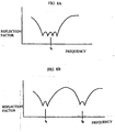
- the radiation electrodes 6 and 12 of the base dielectric substrate 1 and those of the multi-layer dielectric substrate 10 individually resonate, four resonant operations in total are performed. Therefore, for example, by setting the resonant frequencies of the individual radiation electrodes to be near both sides of a set frequency f 1 , as shown in Fig. 8A, with the result of resonant operations of the four radiation electrodes, the band of the set frequency f 1 can be widened.
- the resonant frequencies of the radiation electrodes 6 and 12 of the base dielectric substrate 1 are set to be near the set frequency f 1 and the resonant frequencies of the radiation electrodes 6 and 12 of the multi-layer dielectric substrate 10 are set to be near a set frequency f 2 , as the result of the double resonance of the radiation electrodes 6 and 12 of the base dielectric substrate 1 and the double resonance of the radiation electrodes 6 and 12 of the multi-layer dielectric substrate 10, as shown in Fig. 8B, the bands of the set frequencies f 1 and f 2 can be widened.
- the directions in which the first radiation electrode 6 and the second radiation electrode 12 of a first layer formed on the upper surface 5 of the base dielectric substrate 1 excite are substantially perpendicular to each other.
- the directions in which the first radiation electrode 6 and the second radiation electrode 12 of a second layer formed on the upper surface 11 of the multi-layer dielectric substrate 10 excite are also substantially perpendicular to each other.
- the antenna can be miniaturized. Additionally, by narrowing the gaps ⁇ 1 and ⁇ 2, since the areas for disposing the first and second radiation electrodes can be increased, it is possible to increase the gain of the antenna.
- the first radiation electrodes 6 and the second radiation electrodes 12 of the individual layers are disposed via each of the gaps ⁇ 1 and ⁇ 2, and edges 7 of the first radiation electrodes 6 and edges 13 of the second radiation electrodes 12 are opposed to each other via each of the gaps ⁇ 1 and ⁇ 2.
- the edges 7 and 13 of the first and second radiation electrodes 6 and 12 opposing via each of the gaps ⁇ 1 and ⁇ 2 are oblique lines.
- the direction of a current flowing through the radiation electrode 6 is parallel to the direction of a current flowing through the radiation electrode 12.
- the direction in which the radiation electrode 6 excites becomes parallel to the direction in which the radiation electrode 12 excites.
- the degree of the isolation of the signals between the radiation electrodes of the upper and lower layers can be adjusted by selectively changing the permittivity of the multi-layer dielectric substrate 10. Therefore, by making the combination adjustment of the gap between the radiation electrodes 6 and 12, the gap angle, and the permittivity, prevention of the interference of the signals between the radiation electrodes of the upper and lower layers can be greatly facilitated.
- the concentration of electric-fields on a fringing capacitance between the mounting substrate and the radiation electrodes can be suppressed to concentrate the electric fields on the upper multi-layer dielectric substrate 10 so as to achieve widening of the frequency band.
- Fig. 5 shows the structure of the main part of a surface-mounted antenna according to a fourth embodiment of the present invention.
- the upper end of a feeding connection electrode 2 is extended to the upper end of a front side surface 3 of the base dielectric substrate 1 to couple the feeding connection electrode 2 with the first radiation electrode 6 of the multi-layer dielectric substrate 10 by a capacitance C2.
- the other structural parts are formed in the same manner as those in the third embodiment.
- the antenna of the fourth embodiment operates in the same way as that of the third embodiment to obtain the same advantages as those of the third embodiment.
- the lengths of the gap ⁇ 1 and ⁇ 2 between the radiation electrodes 6 and 12 and the gap angles ⁇ shown in Fig. 5 are different from those shown in Fig. 4, this conceptually shows that interference of the signals between the radiation electrodes 6 and 12 of the upper and lower layers can be prevented by adjusting isolation according to the varied lengths of the gap ⁇ 1 and ⁇ 2 and the gap angles ⁇ .
- Fig. 6 shows the structure of the main parr of a surface-mounted antenna according to a fifth embodiment of the present invention.
- two multi-layer dielectric substrates 10, that is, 10a and 10b are laminated on an upper surface 5 of a base dielectric substrate 1 having the radiation electrodes 6 and 12 of a first layer formed thereon to be integrated with the base dielectric substrate 1.
- the other structural parts are formed in the same manner as those shown in the third embodiment.
- radiation electrodes 6 and 12 of a second layer are formed via a gap ⁇ 2.
- radiation electrodes 6 and 12 of a third layer are formed via a gap ⁇ 3.
- a feeding connection electrode 2 and the first radiation electrode 6 of the base dielectric substrate 1 are capacitively coupled with each other.
- the first radiation electrode 6 of the base dielectric substrate 1 and the first radiation electrode 6 of the multi-layer dielectric substrate 10a are capacitively coupled with each other.
- the first radiation electrode 6 of the multi-layer dielectric substrate 10a and the first radiation electrode 6 of the multi-layer dielectric substrate 10b are also capacitively coupled with each other.
- the first and second radiation electrodes 6 and 12 of the individual layers are coupled with each other via the capacitance of each of the corresponding gaps ⁇ 1, ⁇ 2, and ⁇ 3.
- a feeding signal from a signal source 4 is supplied to all of the radiation electrodes 6 and 12 via each coupling capacitance, and then, a double resonance is performed between the radiation electrodes 6 and 12 of each layer to obtain six multiple resonances in total.
- the fifth embodiment by adjusting the gaps ⁇ 1, ⁇ 2, and ⁇ 3 between the radiation electrodes of the individual layers and the gaps angles ⁇ as needed, directions in which the radiation electrodes of the individual layers vertically adjacent excite can be adjusted in different directions, that is, in non-parallel directions.
- directions in which the radiation electrodes of the individual layers vertically adjacent excite can be adjusted in different directions, that is, in non-parallel directions.
- isolation between the vertically adjacent upper and lower layers can be adjusted.
- the two multi-layer dielectric substrates 10 are laminated on the base dielectric substrate 1, it is also possible to produce many more resonance by laminating and integrating three or more multi-layer dielectric substrates 10 having radiation electrodes 6 and 12 on the upper surface thereof.
- Fig. 7 shows the structure of the main part of a surface-mounted antenna according to a sixth embodiment of the present invention.
- the provided antenna is a capacitance feeding type of antenna.
- a capacitance feeding type of antenna can be easily converted into a direct excitation type of antenna only by changing a feeding circuit, that is, by changing the capacitance feeding circuit into a direct excitation circuit.
- the sixth embodiment shows a typical structure in which the capacitance feeding type of antenna shown in Fig. 4 is converted into the direct excitation type of antenna.
- a feeding connection electrode 2 which is electrically connected to a first radiation electrode 6, is disposed on a side surface of a base dielectric substrate 1.
- a short electrode 17 is formed by branching from a certain point of the feeding connection electrode 2.
- a short electrode 18 conducted to a second radiation electrode 12 is formed near the short electrode 17 to form the direct excitation circuit.
- the first radiation electrode 6 of the base dielectric substrate 1 and the first radiation electrode 6 of the multi-layer dielectric substrate 10 are capacitively coupled with each other.
- the first radiation electrode 6 and the second radiation electrode 12 of the multi-layer dielectric substrate 10 are coupled with each other by the capacitance of a gap ⁇ 2.
- Fig. 9 shows the structure of the main part of a surface-mounted antenna according to a seventh embodiment of the present invention.
- a first radiation electrode 6 is formed on an upper surface 5 of a base dielectric substrate 1.
- a multi-layer dielectric substrate 10 is laminated to be integrated therewith.
- a second radiation electrode 12 is formed on an upper surface 11 of the multi-layer dielectric substrate 10.
- the first radiation electrode 6 is widened to side surfaces 23 and 24 of the base dielectric substrate 1.
- the width of the first radiation electrode 6 is substantially even in the region of a side surface 22, which is the region of a front-end side surface.
- the peripheral edge of the side surface 23 of the radiation electrode 6 forms a bending surface 30 by retreating to the side surface 24.
- the width of the radiation electrode pattern tapers down like a fan-like shape from the front-end side surface 22 to the rear-end side, which is the back surface side of the base dielectric substrate 1.
- a feeding connection electrode 2 and a short electrode 17 are vertically formed on the side surface 22 (front surface) of the base dielectric substrate 1.
- a short electrode 25 is formed by branching from an intermediate point of the feeding connection electrode 2.
- the short electrode 25 branched from the feeding connection electrode 2 in a horizontal direction is perpendicularly bent in a lower direction to form a parallel pattern close to the short electrode 17.
- the lower end of the short electrode 25 is conducted to a grounding electrode 20 on the bottom of the base dielectric substrate 1.
- the upper end of the feeding connection electrode 2 is connected to the first radiation electrode 6 of the upper surface 5 of the base dielectric substrate 1, and the lower end thereof is connected to a signal source 4.
- the first radiation electrode 6 is capacitively coupled with the grounding electrode formed on the bottom of the base dielectric substrate 1 at the side surface (left side surface) 24. As a result, the side surface 24 is an open end 15.
- an electrode 21 is formed from the upper end to the intermediate part of the side surface 23.
- the lower end face of the electrode 21 is capacitively coupled with the upper end face of the grounding electrode 20 extended from the bottom of the base dielectric substrate 1 via a gap by a capacitance C.
- the second radiation electrode 12 formed on an upper surface 11 of the multi-layer dielectric substrate 10 makes a pattern whose right and left positions are substantially reversed to those of the pattern of the first radiation electrode 6 excepting a connecting electrode pattern. That is, the pattern of the second radiation electrode 12 is substantially 180-degree reversed thereto.
- the second radiation electrode 12 is connected to the short electrode 17 of the base dielectric substrate 1 by a short electrode 17 disposed on the side surface (front surface) 22 of the same side as that of the base dielectric substrate 1.
- Another electrode 21 electrically connected to the second radiation electrode 12 is disposed close to the rear end of the side surface (right side surface) 23 of the multi-layer dielectric substrate 10.
- the electrode 21 on the multi-layer dielectric substrate 10 is electrically connected to the upper end of the electrode 21 disposed on the side surface 23 of the base dielectric substrate 1.
- the capacitive coupling part is an open end 16 of the second radiation electrode 12.
- a feeding signal supplied from the signal source 4 is supplied to the first radiation electrode 6 from a feeding connection electrode 2 serving as a short.
- a current flows to the open end 15 from the short in the first radiation electrode 6, which is excited.
- the vector direction of the current flow is equivalent to a direction A in which the first radiation electrode 6 excites.
- a feeding signal supplied from the signal source 4 is sent to the second radiation electrode 12 via the magnetic-field coupling between the short electrode 25 and the short electrode 17.
- a current flows from the short to the open end 16 in the second radiation electrode 12.
- the vector direction of the current flow is equivalent to a direction B in which the second radiation electrode 6 excites. In this direction, the second radiation electrode 12 is excited.
- the direction (direction A) in which the first radiation electrode 6 excites is set to be substantially perpendicular to the direction (direction B) in which the second radiation electrode 12 excites, interference of resonant signals between the radiation electrodes 6 and 12 can be suppressed, thereby leading to widening of the frequency band.
- the permittivity of the multi-layer dielectric substrate 10 by selectively adjusting the permittivity of the multi-layer dielectric substrate 10, isolation between the upper and lower radiation electrodes 6 and 12 can be adjusted.
- the permittivity of the multi-layer dielectric substrate 10 to be higher than the permittivity of the base dielectric substrate 1, a wider frequency band can be obtained.
- Fig. 10 shows a communication apparatus according to an embodiment of the present invention.
- a mounting substrate 50 is disposed inside a case 31 of a communication apparatus 30 such as a cellular phone.
- a feeding circuit 32 is formed on the mounting substrate 50.
- a surface-mounted antenna 100 is mounted on a grounded surface 33 (grounding electrode) of the mounting substrate 50.
- the surface-mounted antenna 100 is connected to the feeding circuit 32 having a signal source 4 directly or by a capacitive coupling.
- the feeding circuit 32 is connected to a transmission circuit 35 and a reception circuit 36 via a switching circuit 34.
- a feeding signal of the signal source 4 of the feeding circuit 32 is supplied to the surface-mounted antenna 100 to perform the above-mentioned antenna operation, which is equivalent to the excitations of radiation electrodes 6 and 12. Then, by the switching operations of the switching circuit 34, signal transmission/reception can be smoothly performed.
- both directions need not to be substantially perpendicular to each other.
- both directions only need to intersect with each other at an angle capable of suppressing interference between the resonant signals of the first radiation electrode 6 and second radiation electrode 12 to a degree in which no problem practically occurs.
- the shapes (electrode patterns) of the first radiation electrode 6 and second radiation electrode 12 are not limited to those of the above embodiments. Other electrode shapes can be used according to performance specifications.
- the communication apparatus is not limited to a cellular phone.
- the present invention can be applied to various communication apparatuses incorporating antennas.
- the multi-layer dielectric substrate is laminated on the upper surface of the base dielectric substrate to be integrated therewith, and the direction in which the first radiation electrode formed on the upper surface of the base dielectric substrate excites differs from the direction in which the second radiation electrode formed on the upper surface of the multi-layer dielectric substrate excites. That is, the above directions are not parallel to each other. With this arrangement, interference of the resonant signals between the lower first radiation electrode and the upper second radiation electrode can be effectively suppressed. Therefore, isolation is enhanced and the band of a used frequency can thereby be widened.
- the first radiation electrode formed on the upper surface of the base dielectric substrate is not opposed to the second radiation electrode formed on the upper surface of the multi-layer dielectric substrate, isolation can be more enhanced to widen the frequency band.
- the directions in which the lower first radiation electrode and the upper second radiation electrode excite-differ from each other even though the gap between the first radiation electrode on the base dielectric substrate and the second radiation electrode on the multi-layer dielectric substrate in the parallel direction is narrowed, sufficient isolation can be obtained. Therefore, since the gap can be narrowed, the sizes of the antenna and the communication apparatus incorporating the same can be reduced.
- the first and second radiation electrodes as the first-layer radiation electrodes are formed via the gap on the upper surface of the base dielectric substrate, and other first and second radiation electrodes as the second-layer radiation electrodes are formed via the gap on the upper surface of the multi-layer dielectric substrate integrated by being laminated on the upper surface of the base dielectric substrate.
- the antenna and the communication apparatus having this arrangement according to the present invention, since the directions in which the first and second radiation electrodes of each layer excite differ from each other, even though the gap between the first and second radiation electrodes formed on each layer is narrowed, the isolation of signals between the first and second radiation electrodes can be enhanced. Since the gap can be narrowed, the antenna and the communication apparatus can be miniaturized. Moreover, by narrowing the gap, there is another advantage in that the areas occupied by the radiation electrodes can be increased.
- the edges of the first and second radiation electrodes opposing via the gap are oblique lines, the directions in which the first and second radiation electrodes excite can be set to be different. Moreover, by varying the length and angle of the gap, there is another advantage in that the exciting directions can be easily and freely adjusted.
- the multi-layer dielectric substrate is laminated on the base dielectric substrate, by selectively changing the permittivity of the multi-layer dielectric substrate, the isolation between the radiation electrode formed on the base dielectric substrate and the radiation electrode formed on the multi-layer dielectric substrate can be easily adjusted.
- the permittivity of the multi-layer dielectric substrate of a specified layer by selectively changing the permittivity of the multi-layer dielectric substrate of a specified layer, the isolation between the upper and lower radiation electrodes of the specified multi-layer dielectric substrate can be easily adjusted.
- the frequency band for communications can be widened by enhancing the isolation between the radiation electrodes, communication reliability can also be improved.
Landscapes
- Engineering & Computer Science (AREA)
- Computer Networks & Wireless Communication (AREA)
- Physics & Mathematics (AREA)
- Electromagnetism (AREA)
- Waveguide Aerials (AREA)
- Details Of Aerials (AREA)
- Variable-Direction Aerials And Aerial Arrays (AREA)
Applications Claiming Priority (2)
| Application Number | Priority Date | Filing Date | Title |
|---|---|---|---|
| JP26380999A JP3639753B2 (ja) | 1999-09-17 | 1999-09-17 | 表面実装型アンテナおよびそれを用いた通信装置 |
| JP26380999 | 1999-09-17 |
Publications (3)
| Publication Number | Publication Date |
|---|---|
| EP1085595A2 true EP1085595A2 (fr) | 2001-03-21 |
| EP1085595A3 EP1085595A3 (fr) | 2004-01-14 |
| EP1085595B1 EP1085595B1 (fr) | 2009-04-15 |
Family
ID=17394552
Family Applications (1)
| Application Number | Title | Priority Date | Filing Date |
|---|---|---|---|
| EP00119656A Expired - Lifetime EP1085595B1 (fr) | 1999-09-17 | 2000-09-08 | Antenne montable en surface et appareil de communication utilisant celle-ci |
Country Status (5)
| Country | Link |
|---|---|
| US (1) | US6297777B1 (fr) |
| EP (1) | EP1085595B1 (fr) |
| JP (1) | JP3639753B2 (fr) |
| CN (1) | CN1151587C (fr) |
| DE (1) | DE60042000D1 (fr) |
Cited By (2)
| Publication number | Priority date | Publication date | Assignee | Title |
|---|---|---|---|---|
| FR2825837A1 (fr) * | 2001-06-12 | 2002-12-13 | Cit Alcatel | Antenne compacte multibande |
| GB2478991B (en) * | 2010-03-26 | 2014-12-24 | Microsoft Corp | Dielectric chip antennas |
Families Citing this family (16)
| Publication number | Priority date | Publication date | Assignee | Title |
|---|---|---|---|---|
| DE60115131T2 (de) * | 2000-04-14 | 2006-08-17 | Hitachi Metals, Ltd. | Chip-Antennenelement und dieses aufweisendes Nachrichtenübertragungsgerät |
| US6466174B2 (en) * | 2001-02-08 | 2002-10-15 | Centurion Wireless Technologies, Inc. | Surface mount CHIP antenna |
| JP2002271119A (ja) * | 2001-03-06 | 2002-09-20 | Ngk Insulators Ltd | アンテナ |
| EP1387433B1 (fr) | 2001-04-23 | 2006-05-31 | Yokowo Co., Ltd | Antenne a large bande pour communication de service mobile |
| US6675461B1 (en) * | 2001-06-26 | 2004-01-13 | Ethertronics, Inc. | Method for manufacturing a magnetic dipole antenna |
| JP3921425B2 (ja) * | 2002-07-19 | 2007-05-30 | 株式会社ヨコオ | 表面実装型アンテナおよび携帯無線機 |
| JP2004186730A (ja) * | 2002-11-29 | 2004-07-02 | Tdk Corp | チップアンテナ、チップアンテナユニットおよびそれを用いた無線通信装置 |
| JP4013814B2 (ja) * | 2003-04-07 | 2007-11-28 | 株式会社村田製作所 | アンテナ構造およびそれを備えた通信機 |
| FI118782B (fi) * | 2005-10-14 | 2008-03-14 | Pulse Finland Oy | Säädettävä antenni |
| EP2065975A1 (fr) * | 2006-09-20 | 2009-06-03 | Murata Manufacturing Co. Ltd. | Structure d'antenne et dispositif de communication sans fil l'employant |
| KR100867507B1 (ko) * | 2007-07-12 | 2008-11-07 | 삼성전기주식회사 | 칩 안테나 |
| US7990604B2 (en) | 2009-06-15 | 2011-08-02 | Qualcomm Mems Technologies, Inc. | Analog interferometric modulator |
| KR102120281B1 (ko) | 2016-07-27 | 2020-06-08 | 후아웨이 테크놀러지 컴퍼니 리미티드 | 무선 수신/송신 디바이스 및 기지국 |
| CN106961008B (zh) * | 2017-04-06 | 2019-03-29 | 京东方科技集团股份有限公司 | 天线结构及其驱动方法和天线系统 |
| CN112467375B (zh) * | 2018-06-11 | 2022-09-09 | 深圳迈睿智能科技有限公司 | 具有抗干扰设置的天线及其制造方法 |
| TWI749987B (zh) * | 2021-01-05 | 2021-12-11 | 友達光電股份有限公司 | 天線結構及陣列天線模組 |
Citations (2)
| Publication number | Priority date | Publication date | Assignee | Title |
|---|---|---|---|---|
| US5631660A (en) | 1993-08-06 | 1997-05-20 | Fujitsu Limited | Antenna module for a portable radio equipment with a grounding conductor |
| US5781158A (en) | 1995-04-25 | 1998-07-14 | Young Hoek Ko | Electric/magnetic microstrip antenna |
Family Cites Families (3)
| Publication number | Priority date | Publication date | Assignee | Title |
|---|---|---|---|---|
| EP0777295B1 (fr) * | 1995-11-29 | 2003-05-28 | Ntt Mobile Communications Network Inc. | Antenne à deux fréquences de résonance |
| US6002369A (en) * | 1997-11-24 | 1999-12-14 | Motorola, Inc. | Microstrip antenna and method of forming same |
| JP3351363B2 (ja) * | 1998-11-17 | 2002-11-25 | 株式会社村田製作所 | 表面実装型アンテナおよびそれを用いた通信装置 |
-
1999
- 1999-09-17 JP JP26380999A patent/JP3639753B2/ja not_active Expired - Fee Related
-
2000
- 2000-09-08 EP EP00119656A patent/EP1085595B1/fr not_active Expired - Lifetime
- 2000-09-08 DE DE60042000T patent/DE60042000D1/de not_active Expired - Lifetime
- 2000-09-15 CN CNB001331310A patent/CN1151587C/zh not_active Expired - Fee Related
- 2000-09-15 US US09/662,665 patent/US6297777B1/en not_active Expired - Lifetime
Patent Citations (2)
| Publication number | Priority date | Publication date | Assignee | Title |
|---|---|---|---|---|
| US5631660A (en) | 1993-08-06 | 1997-05-20 | Fujitsu Limited | Antenna module for a portable radio equipment with a grounding conductor |
| US5781158A (en) | 1995-04-25 | 1998-07-14 | Young Hoek Ko | Electric/magnetic microstrip antenna |
Non-Patent Citations (1)
| Title |
|---|
| SANAD M: "A Compact Dual-Broadband Microstrip Antenna having both stacked and planar parasitic Elements", IEEE ANTENNAS AND PROPAGATION SOCIETY INTERNATIONAL SYMPOSIUM 1996 DIGEST, vol. 1, 21 July 1996 (1996-07-21), pages 6 - 9 |
Cited By (5)
| Publication number | Priority date | Publication date | Assignee | Title |
|---|---|---|---|---|
| FR2825837A1 (fr) * | 2001-06-12 | 2002-12-13 | Cit Alcatel | Antenne compacte multibande |
| WO2002101874A1 (fr) * | 2001-06-12 | 2002-12-19 | Alcatel | Antenne compacte multibande |
| US6930642B2 (en) | 2001-06-12 | 2005-08-16 | Alcatel | Compact multiband antenna |
| GB2478991B (en) * | 2010-03-26 | 2014-12-24 | Microsoft Corp | Dielectric chip antennas |
| US9059510B2 (en) | 2010-03-26 | 2015-06-16 | Microsoft Technology Licensing, Llc | Dielectric chip antennas |
Also Published As
| Publication number | Publication date |
|---|---|
| CN1151587C (zh) | 2004-05-26 |
| JP3639753B2 (ja) | 2005-04-20 |
| CN1296309A (zh) | 2001-05-23 |
| JP2001085934A (ja) | 2001-03-30 |
| US6297777B1 (en) | 2001-10-02 |
| EP1085595A3 (fr) | 2004-01-14 |
| EP1085595B1 (fr) | 2009-04-15 |
| DE60042000D1 (de) | 2009-05-28 |
Similar Documents
| Publication | Publication Date | Title |
|---|---|---|
| US6297777B1 (en) | Surface-mounted antenna and communication apparatus using same | |
| JP3554960B2 (ja) | アンテナ装置およびそれを用いた通信装置 | |
| JP4423809B2 (ja) | 複共振アンテナ | |
| US6958730B2 (en) | Antenna device and radio communication equipment including the same | |
| CN1825697B (zh) | 天线模块及使用该天线模块的电子装置 | |
| KR100432100B1 (ko) | 표면 실장형 안테나 및 이 표면 실장형 안테나를 포함하는통신 장치 | |
| JP3180683B2 (ja) | 表面実装型アンテナ | |
| KR100533624B1 (ko) | 듀얼 피딩 포트를 갖는 멀티밴드 칩 안테나 및 이를사용하는 이동 통신 장치 | |
| EP1248316B1 (fr) | Antenne et appareil de communication muni de cette antenne | |
| JP4868128B2 (ja) | アンテナ装置及びそれを用いた無線通信機器 | |
| EP1164656A2 (fr) | Système d'antenne et unité radio l'utilisant | |
| KR20010080521A (ko) | 표면 실장형 안테나 및 표면 실장형 안테나를 구비한 통신장치 | |
| JP2006311499A (ja) | 車両用ガラスアンテナ | |
| JP2004088218A (ja) | 平面アンテナ | |
| JP6323455B2 (ja) | アンテナ装置 | |
| US8643549B2 (en) | Multi-resonant antenna | |
| KR20040018125A (ko) | 안테나 구조 및 그것을 구비한 통신기 | |
| WO2011086723A1 (fr) | Antenne et appareil de communication sans fil | |
| EP1564837A2 (fr) | Antenne et dispositif de communication sans fil avec antenne | |
| JP2009111999A (ja) | マルチバンドアンテナ | |
| EP4113746A1 (fr) | Antenne et terminal | |
| KR100874394B1 (ko) | 표면 실장형 안테나 및 그것을 탑재한 휴대형 무선 장치 | |
| JP2006287986A (ja) | アンテナ及びそれを用いた無線装置 | |
| US11024965B2 (en) | Dual band antenna device | |
| GB2359929A (en) | Antenna device and communication apparatus |
Legal Events
| Date | Code | Title | Description |
|---|---|---|---|
| PUAI | Public reference made under article 153(3) epc to a published international application that has entered the european phase |
Free format text: ORIGINAL CODE: 0009012 |
|
| 17P | Request for examination filed |
Effective date: 20000908 |
|
| AK | Designated contracting states |
Kind code of ref document: A2 Designated state(s): AT BE CH CY DE DK ES FI FR GB GR IE IT LI LU MC NL PT SE |
|
| AX | Request for extension of the european patent |
Free format text: AL;LT;LV;MK;RO;SI |
|
| PUAL | Search report despatched |
Free format text: ORIGINAL CODE: 0009013 |
|
| AK | Designated contracting states |
Kind code of ref document: A3 Designated state(s): AT BE CH CY DE DK ES FI FR GB GR IE IT LI LU MC NL PT SE |
|
| AX | Request for extension of the european patent |
Extension state: AL LT LV MK RO SI |
|
| AKX | Designation fees paid |
Designated state(s): DE FR GB |
|
| 17Q | First examination report despatched |
Effective date: 20040826 |
|
| RAP1 | Party data changed (applicant data changed or rights of an application transferred) |
Owner name: MURATA MANUFACTURING CO., LTD. |
|
| GRAP | Despatch of communication of intention to grant a patent |
Free format text: ORIGINAL CODE: EPIDOSNIGR1 |
|
| GRAS | Grant fee paid |
Free format text: ORIGINAL CODE: EPIDOSNIGR3 |
|
| GRAA | (expected) grant |
Free format text: ORIGINAL CODE: 0009210 |
|
| AK | Designated contracting states |
Kind code of ref document: B1 Designated state(s): DE FR GB |
|
| REG | Reference to a national code |
Ref country code: GB Ref legal event code: FG4D |
|
| REF | Corresponds to: |
Ref document number: 60042000 Country of ref document: DE Date of ref document: 20090528 Kind code of ref document: P |
|
| PLBE | No opposition filed within time limit |
Free format text: ORIGINAL CODE: 0009261 |
|
| STAA | Information on the status of an ep patent application or granted ep patent |
Free format text: STATUS: NO OPPOSITION FILED WITHIN TIME LIMIT |
|
| 26N | No opposition filed |
Effective date: 20100118 |
|
| GBPC | Gb: european patent ceased through non-payment of renewal fee |
Effective date: 20090908 |
|
| PG25 | Lapsed in a contracting state [announced via postgrant information from national office to epo] |
Ref country code: GB Free format text: LAPSE BECAUSE OF NON-PAYMENT OF DUE FEES Effective date: 20090908 |
|
| REG | Reference to a national code |
Ref country code: FR Ref legal event code: PLFP Year of fee payment: 17 |
|
| PGFP | Annual fee paid to national office [announced via postgrant information from national office to epo] |
Ref country code: DE Payment date: 20160921 Year of fee payment: 17 |
|
| PGFP | Annual fee paid to national office [announced via postgrant information from national office to epo] |
Ref country code: FR Payment date: 20160921 Year of fee payment: 17 |
|
| REG | Reference to a national code |
Ref country code: DE Ref legal event code: R119 Ref document number: 60042000 Country of ref document: DE |
|
| REG | Reference to a national code |
Ref country code: FR Ref legal event code: ST Effective date: 20180531 |
|
| PG25 | Lapsed in a contracting state [announced via postgrant information from national office to epo] |
Ref country code: DE Free format text: LAPSE BECAUSE OF NON-PAYMENT OF DUE FEES Effective date: 20180404 |
|
| PG25 | Lapsed in a contracting state [announced via postgrant information from national office to epo] |
Ref country code: FR Free format text: LAPSE BECAUSE OF NON-PAYMENT OF DUE FEES Effective date: 20171002 |