EP1085458B1 - Hybrid printmask for multidrop inkjet printer - Google Patents
Hybrid printmask for multidrop inkjet printer Download PDFInfo
- Publication number
- EP1085458B1 EP1085458B1 EP00307429A EP00307429A EP1085458B1 EP 1085458 B1 EP1085458 B1 EP 1085458B1 EP 00307429 A EP00307429 A EP 00307429A EP 00307429 A EP00307429 A EP 00307429A EP 1085458 B1 EP1085458 B1 EP 1085458B1
- Authority
- EP
- European Patent Office
- Prior art keywords
- nozzles
- printheads
- ink
- drops
- printhead
- Prior art date
- Legal status (The legal status is an assumption and is not a legal conclusion. Google has not performed a legal analysis and makes no representation as to the accuracy of the status listed.)
- Expired - Lifetime
Links
Images


Classifications
-
- B—PERFORMING OPERATIONS; TRANSPORTING
- B41—PRINTING; LINING MACHINES; TYPEWRITERS; STAMPS
- B41J—TYPEWRITERS; SELECTIVE PRINTING MECHANISMS, i.e. MECHANISMS PRINTING OTHERWISE THAN FROM A FORME; CORRECTION OF TYPOGRAPHICAL ERRORS
- B41J2/00—Typewriters or selective printing mechanisms characterised by the printing or marking process for which they are designed
- B41J2/005—Typewriters or selective printing mechanisms characterised by the printing or marking process for which they are designed characterised by bringing liquid or particles selectively into contact with a printing material
- B41J2/01—Ink jet
- B41J2/21—Ink jet for multi-colour printing
- B41J2/2132—Print quality control characterised by dot disposition, e.g. for reducing white stripes or banding
-
- G—PHYSICS
- G06—COMPUTING OR CALCULATING; COUNTING
- G06K—GRAPHICAL DATA READING; PRESENTATION OF DATA; RECORD CARRIERS; HANDLING RECORD CARRIERS
- G06K15/00—Arrangements for producing a permanent visual presentation of the output data, e.g. computer output printers
- G06K15/02—Arrangements for producing a permanent visual presentation of the output data, e.g. computer output printers using printers
- G06K15/10—Arrangements for producing a permanent visual presentation of the output data, e.g. computer output printers using printers by matrix printers
- G06K15/102—Arrangements for producing a permanent visual presentation of the output data, e.g. computer output printers using printers by matrix printers using ink jet print heads
- G06K15/105—Multipass or interlaced printing
- G06K15/107—Mask selection
Definitions
- the present invention relates generally to modes of printing with swath-type printing systems. It relates more particularly to printmodes for improving the print quality of output produced by the printhead portion of an inkjet printer.
- Inkjet printers and thermal inkjet printers in particular, have come into widespread use in businesses and homes because of their low cost, high print quality, and color printing capability.
- the operation of such printers is relatively straightforward.
- drops of a colored ink are emitted onto the print media such as paper or transparency film during a printing operation, in response to commands electronically transmitted to the printhead.
- These drops of ink combine on the print media to form the text and images perceived by the human eye.
- Inkjet printers may use a number of different ink colors.
- One or more printheads may be contained in a print cartridge, which may either contain the supply of ink for each printhead or be connected to an ink supply located off-cartridge.
- An inkjet printer frequently can accommodate two to four print cartridges.
- the cartridges typically are mounted side-by-side in a carriage which scans the cartridges back and forth within the printer in a forward and a rearward direction above the media during printing such that the cartridges move sequentially over given locations, called pixels, arranged in a row and column format on the media which is to be printed.
- Each print cartridge typically has an arrangement of printhead nozzles through which the ink is controllably ejected onto the print media, and thus a certain width of the media corresponding to the layout of the nozzles on the print cartridge, can be printed during each scan, forming a printed swath.
- the printer also has a print medium advance mechanism which moves the media relative to the printheads in a direction generally perpendicular to the movement of the carriage so that, by combining scans of the print cartridges back and forth across the media with the advance of the media relative to the printheads, ink can be deposited on the entire printable area of the media.
- the quality of the printed output is a very important feature to purchasers of inkjet printers, and therefore manufacturers of inkjet printers pay a great deal of attention to providing a high level of print quality in their printers.
- Aberrations in the printhead nozzles can undesirably reduce print quality; such aberrations include, for example, not ejecting ink at all, ejecting an incorrect volume of ink in a drop, producing irregularly shaped drops with artifacts such as tails, or producing a spray of extraneous droplets in addition to the desired drop.
- Another common type of nozzle aberration is directionality error, also known as dot placement error, in which the drops of ink are not precisely printed in the intended locations on the print media.
- Different types of printheads can exhibit different types of dot placement errors; these errors are typically due to the design of the printhead and can be characterized for printheads of that particular type.
- Banding is more objectionable in areas of the image that contain midtones, rather than highlights (light) or saturated (dark) areas. Dot placement errors are difficult to see in an area of highlights because there is typically so much white space (unprinted areas of the print medium) between the drops of ink that the placement errors are not readily perceived by the human eye. Saturated areas do not exhibit much banding because they contain very little white space, and the large volumes of ink placed in these areas hide most placement errors. But in midtone areas, which have moderate amounts of both white space and ink, small errors in dot placement can have a large effect on how much white space a person perceives.
- the defective nozzle will only print one out of every four drops in that row, making the impact of the defective nozzle less objectionable. While the above example, for illustration, used a broken nozzle, the same principle applies to nozzles with directionality errors which print ink at incorrect locations.
- a multipass printmode where all nozzles can deposit the same number of drops of ink is often insufficient to improve print quality to an acceptable level, particularly when specific groups of nozzles have worse errors than other groups, as in the case of swath height error as described above. Therefore, some other approaches to improving print-quality have modified the printmode such that all nozzles no longer print the same number of ink drops. For instance, a printmode which prints with only the middle nozzles of a printhead which exhibits swath height error results in improved print quality.
- such an approach has the drawback of significantly increasing the amount of time it takes to print a page, because a smaller swath is printed on each pass.
- printmodes improve print quality by printing using all nozzles, but depositing fewer drops from the end nozzles than the middle nozzles. Examples of such printmodes are described in the co-pending and commonly-assigned European patent application Ser. No. 99301151.9, by Vinals, filed February 17, 1999, titled “Printing Apparatus and Method” (Attorney Docket No. 60980088), which is hereby incorporated by reference in its entirety. Other such examples are described in the above-referenced copending and commonly-owned U.S. patent application Ser. No. by Askeland titled “Banding Reduction in Multipass Printing" (Attorney Docket No. 10980872-1).
- EP 517 543 discloses an ink-jet print head with a plurality of discharging portions which are arranged to main-scan in a direction perpendicular to the direction of the discharging portion arrangement to thereby record a first image area. Sub-scanning of the head is also performed. Before the head is main-scanned to record a second image area, the sub-scanning is performed so that a few discharging portions on an upper edge portion of the head in second main-scanning overlap part of the first image area. Ink droplets land on pixels in the overlapping portion twice for each main-scanning, and image density of the pixels in the overlapping portion is controlled by the sum number of the landing ink droplets. This enables image density unevenness of image density, a "black stripe banding" or a "white stripe banding" in a boundary of an image area being recorded in each main-scanning to be markedly reduced.
- the present invention provides a multipass swath printing system that improves the quality of the printed output by enabling lower-quality nozzles with a greater tendency toward dot placement errors to deposit into a specific pixel location a small number of drops in each of several printing passes, and enabling higher-quality nozzles with a lesser tendency toward dot placement errors to deposit into a specific pixel location many drops rapidly during at least one of the printing passes. Because the number of drops enabled for deposition from all nozzles is substantially identical, such a printing system provides improved print quality without a significant reduction in useful life of the printhead.
- a multipass swath printer comprising:
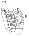
- An embodiment of the printing system includes a printhead mounted in a carriage which is attached to a frame for relative motion with respect to a print medium.
- the printhead has an arrangement of nozzles through which ink is ejected onto a pixel grid of multiple rows on the print medium when the carriage makes a printing pass.
- the system also contains a print controller which activates the nozzles to deposit the ink onto the medium, as governed by a printmask.
- the printmask defines predetermined groups of nozzles to be activated to deposit ink at specific locations in the pixel grid during multiple printing passes of the printhead over the print medium, and the amount of ink to be deposited into the specific locations, based on statistical or theoretical determination of expected dot placement error from the nozzles.
- the printmask has a "hi-fipe" mask subpattern associated with a first group of the nozzles enabling each nozzle to deposit a small number of drops (typically one) into specific locations during each of several of the passes, and a "multidrop" mask subpattern associated with a second group of the nozzles enabling each nozzle to many drops (typically two to four) rapidly into specific locations during at least one of the passes.
- the first group of nozzles is substantially near ends of the printhead, and the second group of nozzles is substantially away from the ends of the printhead.
- the printmask also has a composite mask subpattern associated with a third group of the nozzles enabling each nozzle to both deposit a small number of drops into specific locations during each of several of the passes, and many drops rapidly into specific locations during at least one of the passes.
- the third group of nozzles is disposed between the first and second groups, and the mask subpattern is preferentially graduated such that the small number of drops predominate for nozzles adjacent the first group, and the many drops predominate for nozzles adjacent the second group
- More than one printhead may be included in the swath printing system.
- all the printheads are aligned relative to each other such that each printhead deposits the ink in substantially an identical swath in a single pass.
- the printheads are offset relative to each other such that each printhead deposits the inks in substantially a different swath in a single pass.
- the printheads are partially aligned relative to each other such that two adjacent printheads deposit the inks in an overlapping swath in a single printing pass.
- Each printhead may be mounted in an individual cartridge, or multiple printheads may be mounted in a same cartridge, such as a tri-color cartridge containing three printheads.
- the three printheads may be aligned relative to each other such that the printheads deposit the inks in substantially an identical swath in a single printing pass, or may be offset relative to each other such that the printheads deposit the inks in different swaths in a single printing pass.
- the present invention may also be implemented as a method for incremental printing with an inkjet swath printer.
- the method preferably includes establishing a pixel grid on a print medium by depositing drops of ink in multiple printing passes of a printhead over the print medium in a scan direction and advancing the medium in a media advance direction between at least some of the multiple printing passes, and printing into a specific pixel of the grid by depositing both a small number of drops in each of several of the printing passes and many drops rapidly during at least one of the printing passes.
- all nozzles are enabled to print substantially the same amount of ink into the pixel grid.
- the first group of nozzles is substantially near ends of the printhead, and the second group of nozzles is substantially away from the ends of the printhead.
- Each printhead 21 has a plurality of nozzles 24 through which drops of ink 26a-b are ejected onto the print medium 18 to form an image, which may contain any combination of text, graphics, or photographs.
- the plurality of nozzles 24 is logically arranged as a linear array of nozzles substantially orthogonal to a scan axis 4.
- each printhead typically contains a different color ink.
- the carriage 20 is moveable along the scan axis 4 by a carriage advance mechanism, indicated generally at 12, mounted within the frame 11.
- a printmask 62 is used by the print controller 58 to govern the deposition of ink drops from the printhead 21.
- a separate printmask 62 exists for each discrete intensity level of color (eg. light to dark) supported by the printer 10.
- the printmask 62 has a mask pattern which both (a) acts like a "gate" to enable the nozzle positioned adjacent the row to print, or disable that nozzle from printing, on that pixel location 19, and (b) defines the number of drops to be deposited from enabled nozzles. Whether or not the pixel will actually be printed on by the corresponding enabled nozzle depends on whether the image data 54 to be printed requires a pixel of that ink color in that pixel location.
- printheads are typically formed on silicon substrates.
- One or more printheads, each for a different ink, may be formed on a single substrate.
- a preferred embodiment of a printhead 21 has two vertical columns 70a-b of nozzles 24 which, when the printhead 21 is installed in the printer 10, are perpendicular to the scan axis 4.
- the columnar vertical spacing 74 between adjacent nozzles in a column is typically 1/300th inch in present-day printheads.
- the print controller 58 would print a vertical column of 1/600th inch pixel locations on the print medium 18 by depositing ink from column 70a, then moving the printhead 21 in the scan axis direction 4 an amount equal to the inter-column distance 76 before depositing ink from column 70b.
- the misdirecting nozzles that contribute to swath height error are most frequently located in sections 78 adjacent to the top and bottom ends of the printhead 21.
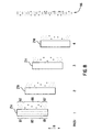
- the first is "hi-fipe" printing, a printmode technique best illustrated in FIG. 6A in which, instead of printing a pixel on the medium 18 using a normal-size ink drop 26c deposited on one particular printing pass, a number of smaller ink drops 26d are deposited in a number of different printing passes in order to completely deposit the equivalent amount of ink in the normal-size drop 26c on that pixel. Typically, only one smaller ink drop 26d is deposited in each different printing pass.
- hi-fipe printing reduces the undesireable effects of dot placement error because different nozzles print the pixel location in different passes, it is less effective at covering white space in mid-tone regions of an image because the slight variations in drop placement within a pixel that are required to fill the white space can be difficult to achieve on separate passes from different nozzles.
- the other printmode technique utilized in the present invention is "multidrop" printing, as best illustrated in FIG. 6B, in which many (typically two to four) smaller ink drops 26d are deposited into a target pixel in extremely rapid succession in at least one printing pass to fully ink the pixel.
- the printmask 62 uses both hi-fipe and multipass techniques in a novel manner to define the pattern of ink drops used by the print controller 58 to partially print a swath of the image during each pass.
- the printmask 62 In a given pass of the carriage 20 over the print medium 18 in a multipass printer 10, only certain pixel locations 19 enabled by the printmask 62 can be printed, and the printer 10 deposits the number of drops specified by the printmask 62 for the corresponding pixel locations 19 if the image data so requires.
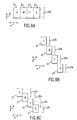
- one drop is enabled for deposition in a pixel location 19 corresponding to the left-most position of the printmask 62 by nozzle number 1 in each of passes two, four, six, and eight, as indicated at 63, for a total of four drops.
- Printmask cells 66 used for in-between nozzles 66 operate in a hybrid hi-fipe/multidrop printmode.
- two drops are enabled for deposition in a pixel location 19 corresponding to the left-most position of the printmask 62 by nozzle number 6 in pass two, with one drop enabled in passes four and six, as indicated at 68, for a total of four drops.
- the allocation between hi-fipe and multidrop allocation varies for in-between nozzles 66, with those nozzles closer to end nozzles 65 exhibiting predominantly hi-fipe behavior, and those nozzles closer to middle nozzles 67 exhibiting predominantly multidrop behavior. This allows a gradual rather than abrupt change between sections of the printhead having higher and lower likelihood of dot placement errors, resulting in higher print quality.
- each nozzle is enabled to print substantially the same amount of ink. Because of the equal print load on all nozzles, a printer according to the present invention does not suffer shortened printhead life due to wearout effects from more frequently used nozzles.
- the print medium 18 is advanced after every printing pass (ignoring the special case of the top and bottom of a page), resulting in printhead locations 21a-d for each printing pass which are offset from each other as indicated in the media advance direction 8.
- the effect of printing many smaller drops and fewer larger drops, when combined with advancing the medium 18 between printing passes, is to create the printed image pattern 86 on the print medium 18 in which the large and small ink drops are intermixed on many rows.
- the number of end nozzles exhibiting greater amounts of dot placement error and the number of middle nozzles exhibiting lesser amounts of dot placement error respectively are usually in a proportion between 1:1 and 1:8. More typically the proportion is between 1:3 and 1:6, with the most common ratio being 1 end nozzle for every 4 middle nozzles.
- all the printheads 21 are partially aligned and partially offset such that two adjacent printheads 21 deposit the inks in a partially overlapping swaths 27c in a single printing pass.
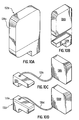
- alternative arrangements for mounting the printheads 21 in the carriage 20 and delivering ink to the printheads are usable with the present invention, as illustrated schematically in FIGS. 10A through 10D.
- Each printhead 21 is housed in a cartridge 132a-132d.
- a cartridge 132a-132d may contain only one printhead 21 for one ink color, or it may contain multiple printheads for multiple colors, such as a tricolor cartridge containing three printheads for cyan, magenta, and yellow respectively.
- the multiple printheads may be constructed on a single substrate or on different substrates.
- the ink may be supplied to the printhead 21 in different ways.
- an ink reservoir 138a is housed within the print cartridge 132a along with the printhead.
- an ink reservoir 138b is detachable from the print cartridge 132b, but the reservoir 138b is attached to the print cartridge 132b when they are installed in the carriage 20.
- the print cartridge 132c does not contain an ink reservoir; ink is supplied to the cartridge 132c instead from an off-chute ink reservoir 138c via a tube 139c.
- FIG. 10A an ink reservoir 138a is housed within the print cartridge 132a along with the printhead.
- an ink reservoir 138b is detachable from the print cartridge 132b, but the reservoir 138b is attached to the print cartridge 132b when they are installed in the carriage 20.
- the print cartridge 132c does not contain an ink reservoir; ink is supplied to the cartridge 132
- a printer can be constructed according to the present invention so as to reduce visually objectionable banding that occurs due to nozzle aberrations without significantly reducing the useful life of the printhead.
- the invention is usable with other types of printheads having lower and higher quality nozzles regardless of where on the printhead those nozzles are located, and of how many nozzles are of lower quality.
- the invention is also usable with different mixes of hi-fipe and multidrop behavior in individual nozzles.
Landscapes
- Engineering & Computer Science (AREA)
- Physics & Mathematics (AREA)
- Mathematical Physics (AREA)
- General Engineering & Computer Science (AREA)
- General Physics & Mathematics (AREA)
- Theoretical Computer Science (AREA)
- Quality & Reliability (AREA)
- Ink Jet (AREA)
- Particle Formation And Scattering Control In Inkjet Printers (AREA)
Priority Applications (1)
| Application Number | Priority Date | Filing Date | Title |
|---|---|---|---|
| EP03075429A EP1310905A1 (en) | 1999-09-20 | 2000-08-30 | Hybrid printmask for multidrop inkjet printer |
Applications Claiming Priority (2)
| Application Number | Priority Date | Filing Date | Title |
|---|---|---|---|
| US399534 | 1999-09-20 | ||
| US09/399,534 US6536869B1 (en) | 1999-09-20 | 1999-09-20 | Hybrid printmask for multidrop inkjet printer |
Related Child Applications (1)
| Application Number | Title | Priority Date | Filing Date |
|---|---|---|---|
| EP03075429A Division EP1310905A1 (en) | 1999-09-20 | 2000-08-30 | Hybrid printmask for multidrop inkjet printer |
Publications (2)
| Publication Number | Publication Date |
|---|---|
| EP1085458A1 EP1085458A1 (en) | 2001-03-21 |
| EP1085458B1 true EP1085458B1 (en) | 2003-10-29 |
Family
ID=23579896
Family Applications (2)
| Application Number | Title | Priority Date | Filing Date |
|---|---|---|---|
| EP00307429A Expired - Lifetime EP1085458B1 (en) | 1999-09-20 | 2000-08-30 | Hybrid printmask for multidrop inkjet printer |
| EP03075429A Withdrawn EP1310905A1 (en) | 1999-09-20 | 2000-08-30 | Hybrid printmask for multidrop inkjet printer |
Family Applications After (1)
| Application Number | Title | Priority Date | Filing Date |
|---|---|---|---|
| EP03075429A Withdrawn EP1310905A1 (en) | 1999-09-20 | 2000-08-30 | Hybrid printmask for multidrop inkjet printer |
Country Status (4)
| Country | Link |
|---|---|
| US (1) | US6536869B1 (enExample) |
| EP (2) | EP1085458B1 (enExample) |
| JP (1) | JP4394267B2 (enExample) |
| DE (1) | DE60006203T2 (enExample) |
Families Citing this family (14)
| Publication number | Priority date | Publication date | Assignee | Title |
|---|---|---|---|---|
| US6851792B2 (en) | 2003-01-08 | 2005-02-08 | Hewlett-Packard Development Company, L.P. | Multiple-pass approach to fluid ejection over media swath in one pass |
| EP1473662B1 (en) * | 2003-04-30 | 2009-08-26 | Hewlett-Packard Development Company, L.P. | Printing apparatus and method |
| US7207652B2 (en) * | 2003-10-17 | 2007-04-24 | Lexmark International, Inc. | Balanced satellite distributions |
| US7108344B2 (en) * | 2003-11-03 | 2006-09-19 | Hewlett-Packard Devleopment Company, L.P. | Printmode for narrow margin printing |
| CN100513174C (zh) * | 2004-07-06 | 2009-07-15 | 佳能株式会社 | 数据处理方法、数据处理装置、掩模制造方法和掩模图案 |
| JP2007055202A (ja) * | 2005-08-26 | 2007-03-08 | Seiko Epson Corp | 印刷方法、印刷システム及びプログラム |
| US9352573B1 (en) | 2006-01-30 | 2016-05-31 | Shahar Turgeman | Ink printing system comprising groups of inks, each group having a unique inkbase composition |
| US10144222B1 (en) | 2006-01-30 | 2018-12-04 | Shahar Turgeman | Ink printing system |
| US9718268B1 (en) | 2006-01-30 | 2017-08-01 | Shahar Turgeman | Ink printing system comprising groups of inks, each group having a unique ink base composition |
| GB0711341D0 (en) | 2007-06-12 | 2007-07-25 | Ffei Ltd | Multilevel screening |
| CN105103529A (zh) * | 2013-01-29 | 2015-11-25 | 惠普发展公司,有限责任合伙企业 | 打印机和处理要打印的图像的方法 |
| WO2014209313A1 (en) * | 2013-06-27 | 2014-12-31 | Hewlett-Packard Development Company, L.P. | Printer with ink control |
| US9656466B1 (en) * | 2016-07-29 | 2017-05-23 | Hewlett-Packard Development Company, L.P. | Introducing grain patterns into images |
| CN109476158B (zh) * | 2016-10-25 | 2020-12-01 | 惠普发展公司,有限责任合伙企业 | 用于维持打印质量参数的打印机和方法 |
Family Cites Families (13)
| Publication number | Priority date | Publication date | Assignee | Title |
|---|---|---|---|---|
| EP0307428B1 (de) | 1987-03-24 | 1991-07-24 | Mvz Maschinenbau Und Verzahnungstechnik, Johannes Falkenstein | Sägewerkzeug |
| US4989016A (en) * | 1989-05-08 | 1991-01-29 | Spectra-Physics, Inc. | Method and apparatus for time distributed use of ink-jets in a printer-plotter |
| JP2891799B2 (ja) * | 1991-06-07 | 1999-05-17 | キヤノン株式会社 | インクジェット記録方法 |
| JPH0564891A (ja) * | 1991-09-09 | 1993-03-19 | Canon Inc | インクジエツト記録装置及びインクジエツト記録方法 |
| US5555006A (en) | 1993-04-30 | 1996-09-10 | Hewlett-Packard Company | Inkjet printing: mask-rotation-only at page extremes; multipass modes for quality and throughput on plastic media |
| US5600353A (en) | 1995-03-01 | 1997-02-04 | Hewlett-Packard Company | Method of transitioning between ink jet printing modes |
| US5654744A (en) | 1995-03-06 | 1997-08-05 | Hewlett-Packard Company | Simultaneously printing with different sections of printheads for improved print quality |
| US5847721A (en) * | 1995-03-06 | 1998-12-08 | Canon Kabushiki Kaisha | Recording apparatus and method |
| ES2116023T3 (es) * | 1995-09-08 | 1998-07-01 | Hewlett Packard Co | Metodo para hacer funcionar una impresora de chorro de tinta e impresora de chorro de tinta que emplea el metodo. |
| US6193347B1 (en) * | 1997-02-06 | 2001-02-27 | Hewlett-Packard Company | Hybrid multi-drop/multi-pass printing system |
| US6019454A (en) * | 1997-03-04 | 2000-02-01 | Hewlett-Packard Company | Multipass inkjet printmodes with randomized dot placement, to minimize patterning and liquid loading |
| US6154227A (en) * | 1997-12-08 | 2000-11-28 | Hewlett-Packard Company | Apparatus and method for printing compensation |
| EP1029688A1 (en) | 1999-02-17 | 2000-08-23 | Hewlett-Packard Company | Printing apparatus and method |
-
1999
- 1999-09-20 US US09/399,534 patent/US6536869B1/en not_active Expired - Lifetime
-
2000
- 2000-08-30 EP EP00307429A patent/EP1085458B1/en not_active Expired - Lifetime
- 2000-08-30 EP EP03075429A patent/EP1310905A1/en not_active Withdrawn
- 2000-08-30 DE DE60006203T patent/DE60006203T2/de not_active Expired - Lifetime
- 2000-09-20 JP JP2000284781A patent/JP4394267B2/ja not_active Expired - Fee Related
Also Published As
| Publication number | Publication date |
|---|---|
| EP1085458A1 (en) | 2001-03-21 |
| DE60006203D1 (de) | 2003-12-04 |
| US6536869B1 (en) | 2003-03-25 |
| JP2001121723A (ja) | 2001-05-08 |
| DE60006203T2 (de) | 2004-07-29 |
| JP4394267B2 (ja) | 2010-01-06 |
| EP1310905A1 (en) | 2003-05-14 |
Similar Documents
| Publication | Publication Date | Title |
|---|---|---|
| US6310640B1 (en) | Banding reduction in multipass printmodes | |
| EP1314561B1 (en) | Method to correct for malfunctioning ink ejection elements in a single pass print mode | |
| US6464316B1 (en) | Bi-directional printmode for improved edge quality | |
| KR970007630B1 (ko) | 잉크제트기록방법 및 장치 | |
| US6278469B1 (en) | Customizing printmasks for printhead nozzle aberrations | |
| EP1176021B1 (en) | Printing system that utilizes print masks with resolutions that are non-integral multiples of each other | |
| EP1085458B1 (en) | Hybrid printmask for multidrop inkjet printer | |
| US20090128594A1 (en) | Defective nozzle replacement in a printer | |
| EP0979734B1 (en) | Multiple pass color shift correction technique for an inkjet printer | |
| JP2003145731A (ja) | 用紙歩進送り誤差および走査幅誤差によるバンディングをなくす印刷マスクを生成するシステムおよび方法 | |
| JPH11151823A (ja) | 印刷方法 | |
| JPH07232434A (ja) | 記録方法および記録装置 | |
| JP4095210B2 (ja) | 記録方法および記録装置 | |
| JP4266593B2 (ja) | 記録装置及びその制御方法 | |
| JP4965992B2 (ja) | インクジェット記録装置、インクジェット記録方法、プログラムおよび記憶媒体 | |
| JP2004174816A (ja) | インクジェット記録装置 | |
| US6302505B1 (en) | Printing system that utilizes continuous and non-continuous firing frequencies | |
| JP4669571B2 (ja) | プリント位置調整方法および該方法を用いるプリント装置 | |
| JP5041915B2 (ja) | 画像形成方法及び画像形成装置 | |
| JPH08258291A (ja) | 混合解像度プリンタにおけるドットの位置合わせ方法及び装置 | |
| US6604812B2 (en) | Print direction dependent firing frequency for improved edge quality | |
| US6739684B1 (en) | Burst mode printing to compensate for colorant migration | |
| JP2001047645A (ja) | インク色が異なる複数のインク滴で一画素を記録する印刷装置 | |
| JP2006218754A (ja) | インクジェット記録装置および方法および記録装置制御方法 |
Legal Events
| Date | Code | Title | Description |
|---|---|---|---|
| PUAI | Public reference made under article 153(3) epc to a published international application that has entered the european phase |
Free format text: ORIGINAL CODE: 0009012 |
|
| AK | Designated contracting states |
Kind code of ref document: A1 Designated state(s): DE FR GB |
|
| AX | Request for extension of the european patent |
Free format text: AL;LT;LV;MK;RO;SI |
|
| 17P | Request for examination filed |
Effective date: 20010309 |
|
| RAP1 | Party data changed (applicant data changed or rights of an application transferred) |
Owner name: HEWLETT-PACKARD COMPANY, A DELAWARE CORPORATION |
|
| 17Q | First examination report despatched |
Effective date: 20010531 |
|
| AKX | Designation fees paid |
Free format text: DE FR GB |
|
| GRAH | Despatch of communication of intention to grant a patent |
Free format text: ORIGINAL CODE: EPIDOS IGRA |
|
| GRAH | Despatch of communication of intention to grant a patent |
Free format text: ORIGINAL CODE: EPIDOS IGRA |
|
| GRAH | Despatch of communication of intention to grant a patent |
Free format text: ORIGINAL CODE: EPIDOS IGRA |
|
| GRAA | (expected) grant |
Free format text: ORIGINAL CODE: 0009210 |
|
| AK | Designated contracting states |
Kind code of ref document: B1 Designated state(s): DE FR GB |
|
| REG | Reference to a national code |
Ref country code: GB Ref legal event code: FG4D |
|
| REF | Corresponds to: |
Ref document number: 60006203 Country of ref document: DE Date of ref document: 20031204 Kind code of ref document: P |
|
| ET | Fr: translation filed | ||
| PLBE | No opposition filed within time limit |
Free format text: ORIGINAL CODE: 0009261 |
|
| STAA | Information on the status of an ep patent application or granted ep patent |
Free format text: STATUS: NO OPPOSITION FILED WITHIN TIME LIMIT |
|
| 26N | No opposition filed |
Effective date: 20040730 |
|
| PGFP | Annual fee paid to national office [announced via postgrant information from national office to epo] |
Ref country code: FR Payment date: 20070817 Year of fee payment: 8 |
|
| REG | Reference to a national code |
Ref country code: FR Ref legal event code: ST Effective date: 20090430 |
|
| PG25 | Lapsed in a contracting state [announced via postgrant information from national office to epo] |
Ref country code: FR Free format text: LAPSE BECAUSE OF NON-PAYMENT OF DUE FEES Effective date: 20080901 |
|
| REG | Reference to a national code |
Ref country code: GB Ref legal event code: 732E Free format text: REGISTERED BETWEEN 20120329 AND 20120404 |
|
| PGFP | Annual fee paid to national office [announced via postgrant information from national office to epo] |
Ref country code: GB Payment date: 20170719 Year of fee payment: 18 Ref country code: DE Payment date: 20170719 Year of fee payment: 18 |
|
| REG | Reference to a national code |
Ref country code: DE Ref legal event code: R119 Ref document number: 60006203 Country of ref document: DE |
|
| GBPC | Gb: european patent ceased through non-payment of renewal fee |
Effective date: 20180830 |
|
| PG25 | Lapsed in a contracting state [announced via postgrant information from national office to epo] |
Ref country code: DE Free format text: LAPSE BECAUSE OF NON-PAYMENT OF DUE FEES Effective date: 20190301 |
|
| PG25 | Lapsed in a contracting state [announced via postgrant information from national office to epo] |
Ref country code: GB Free format text: LAPSE BECAUSE OF NON-PAYMENT OF DUE FEES Effective date: 20180830 |