EP1085264A1 - Process and apparatus for water cooling of a combustion grate - Google Patents
Process and apparatus for water cooling of a combustion grate Download PDFInfo
- Publication number
- EP1085264A1 EP1085264A1 EP00810789A EP00810789A EP1085264A1 EP 1085264 A1 EP1085264 A1 EP 1085264A1 EP 00810789 A EP00810789 A EP 00810789A EP 00810789 A EP00810789 A EP 00810789A EP 1085264 A1 EP1085264 A1 EP 1085264A1
- Authority
- EP
- European Patent Office
- Prior art keywords
- grate
- cooling
- water
- feed water
- cooling water
- Prior art date
- Legal status (The legal status is an assumption and is not a legal conclusion. Google has not performed a legal analysis and makes no representation as to the accuracy of the status listed.)
- Granted
Links
Images


Classifications
-
- F—MECHANICAL ENGINEERING; LIGHTING; HEATING; WEAPONS; BLASTING
- F23—COMBUSTION APPARATUS; COMBUSTION PROCESSES
- F23H—GRATES; CLEANING OR RAKING GRATES
- F23H3/00—Grates with hollow bars
- F23H3/04—Grates with hollow bars externally cooled, e.g. with water, steam or air
-
- F—MECHANICAL ENGINEERING; LIGHTING; HEATING; WEAPONS; BLASTING
- F23—COMBUSTION APPARATUS; COMBUSTION PROCESSES
- F23G—CREMATION FURNACES; CONSUMING WASTE PRODUCTS BY COMBUSTION
- F23G5/00—Incineration of waste; Incinerator constructions; Details, accessories or control therefor
- F23G5/002—Incineration of waste; Incinerator constructions; Details, accessories or control therefor characterised by their grates
-
- F—MECHANICAL ENGINEERING; LIGHTING; HEATING; WEAPONS; BLASTING
- F23—COMBUSTION APPARATUS; COMBUSTION PROCESSES
- F23H—GRATES; CLEANING OR RAKING GRATES
- F23H3/00—Grates with hollow bars
- F23H3/02—Grates with hollow bars internally cooled
Definitions
- the invention relates to a method for cooling a grate for a combustion chamber by means of water and a grate for the combustion of solids, in particular Waste such as household and urban waste, which essentially consists of in rows and side by side water-cooled grate covering units.
- the invention tries to avoid these disadvantages. You have the task is based on a simple, efficient method for cooling a grate for one Fire chamber using water and a suitable grate for burning Develop solids, especially waste, that ensure that always cooling water in sufficient quantity, with sufficient pressure and in integrity is available, so on an emergency cooling system can be dispensed with.
- the grate should be made of inexpensive material. In addition to the movable and fixed rows of grate bars also the central beams, side end panels and the fall of the grate be coolable in the same way. The heat consumption should be ensured in all operating cases his.
- this is the case with a method according to the preamble of Claim 1 achieved in that part of the feed water after the Feed pump and before the feed water control valve from the feed line removed and passed over at least one pressure drop point and then the cooling channels in the grate lining units as cooling water Middle beams, side walls and falling of the grate is fed, the Cooling water when flowing through the cooling channels at least close to Saturated steam temperature is heated and then fed to a customer becomes.
- Another advantage is that when an existing grate furnace is converted on the grate cooling according to the invention, the cooling system without large additional effort connected to the existing feed water pump because the amount of water delivered by the feed pump does not increase becomes. Because a discharge of the amount of heat dissipated into the drum of the boiler is always possible, it can also advantageously dispense with an emergency cooling system become.
- the object of the invention is in accordance with a grate Preamble of claim 9 achieved in that the cooling channels one have a comparatively small inner diameter, its maximum size is designed in such a way that water and steam do not separate, and that the connecting lines (supply and discharge lines) to move Grate parts have an inner diameter that is smaller than that Inner diameter of the cooling channels.
- the supply lines are between Feed water pump and feed water control valve with the feed water line connected, and there is at least one pressure drop point in the supply lines arranged.
- the advantage of the invention is that the cooling system with little Water is operable because all the warmth and part of the sensible Evaporation heat can be used. Therefore, the cooling tubes can only have a small diameter. This in turn has the advantage of being dangerous there is no steam / water separation.
- cooling water / steam mixture is one Steam separator is fed, the separated steam into the drum is passed and the remaining saturated water into the feed water is returned. It can also be used to preheat the cooling water.
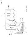
- Fig. 1 shows a longitudinal section of a schematically shown Waste incineration plant, which essentially consists of a water-cooled Combustion grate 1, a combustion chamber 2 arranged above it and one downstream boiler 3 with vertical empty trains 4 and a horizontal one Bundle train 5 exists.
- the firing material 6, in this case garbage, is placed on the grate 1 abandoned and burned with the supply of primary air 7 and 8 secondary air.
- the resulting smoke gases 9 enter the boiler 3 and flow under them Dissipation of heat through the vertical empty trains 4 and the horizontal Bundle train 5 of the boiler 3 and are then not shown Flue gas cleaning system supplied. To this extent, such systems are known.
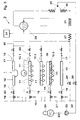
- Fig. 2 shows a schematic representation of the cooling system of the water-cooled grate 1 with downstream boiler 3 in a first Embodiment variant of the invention.
- the grate 1 consists essentially of several rows (10.1, 10.2, 10.3 ...) of side by side Grate covering units 11.
- Fig. 2 are examples of a thermally highly stressed Row 10.1 and two low thermal loads rows 10.2 and 10.3 are shown, the row 10.2 is a fixed grating unit row and the row 10.3 is to represent a moving row of grate pads and the two rows 10.2 and 10.3 are connected by a flexible connecting line 38.
- the Grate covering units 11 can be narrow grate bars or wider grate plates. Adjacent rows overlap like tiles. It can be lengthways of the grate alternately moving and fixed rows may be arranged or all rows can be moved.
- the grate 1 also has side walls 12 on.
- cooling channels 14 for Application of cooling water 15 is arranged, which in Fig. 2 only in the Grate covering unit row 10.3 is shown schematically.
- the cooling channels 14 are preferably coils cast into the grate covering units 11, which are connected to supply lines 16 and discharge lines 17, the Lines 16, 17 are thin tubes, each of which has an expansion circle 18 can have.
- the cooling channels 14 are comparatively small Inner diameter, for example 14 mm. This is designed in such a way that there is no separation of water and steam in the pipes.
- the Inner diameter of the feed lines 16 is much smaller than that Inner diameter of the cooling channels 14, for example 8 mm.
- the Inner diameter of the discharge lines 17 is due to the Vapor phase slightly larger than that of supply lines 16, but still much smaller than the diameter of the cooling channels 14 in the Grate covering units 11.
- each supply line 16 are a three-way valve 19 and at least one Pressure drop point 20 installed.
- these pressure drop points are 20 throttle valves.
- the supply lines 16 all branch off from a line 21, which in turn branches off from the feed water line 22, in which boiler feed water 23 from Feed water tank 24 via the feed water pump 25 and that Feed water control valve 26 via the economizer 27 in the drum 28 of the Boiler 3 is passed.
- the branching of line 21 from line 22 takes place after the feed water pump 25 and before the feed water control valve 26.
- the discharge lines 17 of the cooling systems each have check valves 29 and open into a collecting line 30 which connects to the drum 28 of the boiler 3 connected.
- the drum 28 is still with an evaporator 31 and a superheater 32 with a water injection 33, which via a Injector 36 is regulated in connection.
- the cooling system of the grate consists of several connected in parallel Subsystems.
- a subsystem for cooling is shown by way of example in FIG. 2 of the side walls 12, a subsystem for the cooling of a row of grating units 10.1 in the thermally highly stressed part of the grate 1, a subsystem for the Cooling of two grate lining unit rows 10.2 and 10.3 in the thermally lower loaded part of the grate 1 and a subsystem for cooling the central beams 13.
- cooling water 15 is used, which is a partial stream of demineralized degassed feed water 23 for the operation of the boiler 3.
- This cooling water 15 fits the economizer 27, it is after the feed water pump 25 and before the feed water control valve 26 removed from the feed line 22 and flows via line 15 into the supply lines 16 of the parallel subsystems of the Cooling system.
- the grate cooling thus takes place parallel to the economiser operation. Because part of the Boiler feed water is used as cooling water 15, stands for grate cooling there is always enough water available, which is also perfect Quality and sufficient pressure.
- the supply and discharge of the cooling water 15 to the grate components to be cooled 11, 12, 13 takes place via lines 16 and 17, which pipes with very small Are diameters. Thanks to this small diameter, they are so flexible that the movement of the grate covering units or a partial grate, the z. B. +/- 350 mm may be involved without further ado.
- expansion circles 18 are provided in the lines 16, 17 to compensate for the movement or the thermal expansions.
- the lines 16, 17 can also be made without expansion circles 18 be formed, as in FIG. 2 in the partial cooling system of the central beam 13 is shown.
- throttle valve 20 causes a pressure drop, which at least 1 ⁇ 4 of the pressure drop between the outlet from the Feed water pump 25 and entry into the drum 28 is.
- the cooling water 15 is used for cooling the grate covering units 11 Side walls 12 and the central beam 13 at least up to close to the Saturated steam temperature warmed up. In the normal case, the cooling water 15 except for the Saturated steam temperature warmed so that part of the water 15 evaporates.
- the Cooling water can also be completely or to a large extent (steam content> 0.3) evaporate, d. H. cooling is based on the single-tube boiler principle.
- the heat from the rust components to be cooled is combined with the water or removed the water / steam mixture. Flows per subsystem of the cooling system very little cooling water 15, so all the sensible heat and part of it Evaporation heat is used. Therefore, the cooling channels 14, that is Cooling pipes only of a relatively small diameter.
- the cooling channels 14, that is Cooling pipes only of a relatively small diameter have the advantage that steam and water do not separate. Thanks to the always safe Water supply for cooling does not require the guarantee of emergency running properties, so that no expensive high-alloyed as rust material Cast steel can be used, but cheaper low-alloy material can be used.
- the heated cooling water or water / steam mixture is discharged on the outlet side the lines 17 into a collecting line 30 and from there into the drum 28 guided.
- the cooling takes place at a pressure and temperature level that is only slightly above that of the drum 28. The advantage is that the delivery of the dissipated amount of heat in the drum 28 is always possible.
- a TCA temperature control system measures the outlet temperature of the heated cooling medium in line 17.
- the corresponding signals are passed to the valve 20, which depends on the respective Temperature level controls the amount of cooling water to be supplied 15, d. H. at a high temperature value, the valve 20 will open further, so that more Cooling water 15 is passed into the corresponding cooling channels 14 than at one lower temperature. In this way, the cooling can be optimized in which case slightly superheated steam is generated (single-tube boiler principle).
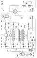
- Fig. 3 shows a schematic representation of the cooling system water-cooled grate with downstream boiler in a second Embodiment variant of the invention. This differs from that in FIG. 1 illustrated and described above only in that as Pressure drops 20 orifices can be used. This is compared to that first embodiment variant cheaper. Thin tubes or manually operated needle valves can be used.
- Fig. 4 shows a third embodiment of the invention analogous to Fig. 2, in which as a consumer of the heated cooling water 15 or the water / steam mixture not the boiler 28, but the feed water tank 24 functions.
- the customer is the Air preheater (economiser 27) or, as shown in dashed lines, one District heating supply device 34.
- the vapor pressure which is set can be lower than the drum pressure, which is advantageously a deeper one Rust surface temperature.
- the manifold 30 in a steam separator 35th lead so that the water / steam mixture gets into the steam separator, the separated steam then into the drum 28 of the boiler 3 lead and the remaining saturated water into the feed water tank 24 attributable, thereby additionally the cooling water 15 via a Heat exchanger 37 can be preheated.
- the water supply line 16 to a moving Grid lining unit row 10.3 leads, this via a flexible connecting line 38 is connected to a fixed grating unit row 10.2 and the Discharge line 17 from the fixed grate lining unit row 10.2 to Bus line 30 leads.
- the discharge line 17 can have a larger diameter, since it does not have to be flexible and that in it contained water / steam mixture creates only a small pressure drop.
Abstract
Description
Die Erfindung betrifft ein Verfahren zur Kühlung eines Rostes für einen Feuerraum mittels Wasser sowie einen Rost zur Verbrennung von Feststoffen, insbesondere Abfällen wie Haus- und Stadtmüll, welcher im wesentlichen aus in Reihen und nebeneinander angeordneten mit Wasser gekühlten Rostbelageinheiten besteht.The invention relates to a method for cooling a grate for a combustion chamber by means of water and a grate for the combustion of solids, in particular Waste such as household and urban waste, which essentially consists of in rows and side by side water-cooled grate covering units.
Es ist bekannter Stand der Technik, stückige Feststoffe, wie z. B. Abfall, in einer Brennkammer, in der Primärluft zugegeben wird, und einer nachgeschalteten Nachbrennkammer, in der Sekundärluft zugegeben wird, zu verbrennen. Üblicherweise wird der Feststoff dabei auf einem Verbrennungsrost umgesetzt. Derartige Roste bestehen meist aus mehreren Rostreihen, welche hintereinander angeordnet sich und sich dachziegelartig überlappen, wobei abwechselnd feststehende und bewegliche Reihen angeordnet sind. Die Reihen werden aus Rostbelageinheiten, z. B. aus dicht miteinander verbundenen schmalen Roststäben oder aus grösseren Rostplatten, gebildet. It is known prior art, lumpy solids, such as. B. waste, in one Combustion chamber in which primary air is added and a downstream one Afterburning chamber in which secondary air is added to burn. The solid is usually reacted on a combustion grate. Such grids usually consist of several rows of grids, one behind the other arranged and overlap like a roof tile, alternating fixed and movable rows are arranged. The rows are out Rust covering units, e.g. B. from tightly connected narrow Grate bars or larger grate plates.
Bei luftgekühlten Verbrennungsrosten wird die Primärluft unter dem Rost zugeführt und strömt von den Unterwindzonen durch Öffnungen im Rostbelag in das darüberliegende Feststoffbett. Der Rostbelag wird dadurch gekühlt (Thomé-Kozmiensky, K. J.: Thermische Abfallbehandlung, EF-Verlag für Energie- und Umwelttechnik GmbH, 2. Auflage 1994, S. 157). Die Verbrennungsluft wird somit zuerst zur Kühlung genutzt und anschliessend zur Verbrennung. Mit der Verknüpfung der Verbrennungsluft und der Kühlluft müssen Kompromisse zwischen Feuerführung und Kühlung eingegangen werden, die nachteilig den Einsatzbereich des Rostes begrenzen. Zusätzlich verstopfen die Verbrennungsluftkanäle/schlitze leicht, weil sie in direktem Kontakt mit dem brennenden Müll stehen. Eine solche Verstopfung blockiert dann auch die Kühlluft, so dass die Kühlung versagt.With air-cooled combustion grates, the primary air is under the grate fed and flows in from the underwind zones through openings in the grate the solid bed above. This cools the grate (Thomé-Kozmiensky, K. J .: Thermal waste treatment, EF publishing house for energy and Umwelttechnik GmbH, 2nd edition 1994, p. 157). The combustion air is thus first used for cooling and then for combustion. With the Linking the combustion air and the cooling air must compromise between fire control and cooling, which adversely affect the Limit the area of use of the grate. In addition, the Combustion air ducts / slits easily because they are in direct contact with the burning garbage. Such a blockage then also blocks the Cooling air so that cooling fails.
Rostkühlsysteme, bei denen die Wärme mit einem separaten Luftkreislauf abgeführt wird, haben folgende Nachteile:
- Die notwendigen Luftmengen bedingen sehr grosse Luftzufuhr- und Luftabfuhrleitungen, die schwierig in die Rostkonstruktion zu integrieren sind.
- Der Leistungsbedarf für die Kühlluftpumpen ist gross, da die Gasgeschwindigkeit der Kühlluft in den Platten hoch sein muss, um einen genügend guten Wärmeübergang zu erreichen, und damit ist der Druckabfall ebenfalls gross.
- The necessary air volumes require very large air supply and air discharge lines, which are difficult to integrate into the grate construction.
- The power requirement for the cooling air pumps is high, since the gas velocity of the cooling air in the plates must be high in order to achieve a sufficiently good heat transfer, and the pressure drop is therefore also great.
Neben den luftgekühlten Verbrennungsrosten sind auch wassergekühlte Verbrennungsroste mit einem von der Primärluft getrennten Kühlwassersystem bekannt, wie beispielsweise in EP 0 621 449 B1, EP 0 757 206 und DE 44 00 992 C1 beschrieben.In addition to the air-cooled combustion grates, there are also water-cooled ones Combustion grates with a cooling water system separated from the primary air known, for example in EP 0 621 449 B1, EP 0 757 206 and DE 44 00 992 C1 described.
Die Rostkühlsysteme, die bei Wassertemperaturen unter 100 °C die Wärme abführen, weisen folgende Nachteile auf:
- Eine Wärmenutzung der abgeführten Wärmemenge ist wegen dem tiefen Temperaturniveau nur schwer oder überhaupt nicht möglich.
- Um bei einer Komponentenhavarie oder bei einem Ausfall des Wärmeabnehmers die Kühlung sicherzustellen, muss ein Notkühlsystem eingesetzt werden, was zusätzliche Investitionskosten verursacht.
- Es muss durch geeignete Massnahmen verhindert werden, dass sich in den Rostplatten/Roststäben Dampfpolster bilden, welche die Kühlung lokal verunmöglichen und zu gefährlichen Dampfschlägen führen können.
- Wasserzufuhr und Wasserabfuhr erfolgen über flexible Wasserschläuche, welche schadensanfällig sind.
- Da die Rosttemperatur immer relativ tief liegt, geht die Wärmeenergie, die zur besseren Verbrennung durch die Luftvorwärmer zugeführt wird, anstelle in da Müllbett zu einem beträchtlichenTeil in das Kühlwasser.
- It is difficult or even impossible to use the amount of heat dissipated due to the low temperature level.
- In order to ensure cooling in the event of a component breakdown or in the event of a heat consumer failure, an emergency cooling system must be used, which causes additional investment costs.
- Appropriate measures must be taken to prevent steam cushions from forming in the grate plates / grate bars, which can make cooling locally impossible and lead to dangerous steam strikes.
- Water supply and drainage take place via flexible water hoses, which are prone to damage.
- Since the grate temperature is always relatively low, the thermal energy which is supplied by the air preheaters for better combustion goes to a considerable extent in the cooling water instead of in the garbage bed.
Die Rostkühlsysteme, die bei Wassertemperaturen über 100 °C (Wasserdruck > 1 bar) die Wärme abführen, haben folgende Nachteile:
- Eine Wärmenutzung der abgeführten Wärmemenge ist zwar möglich, erfordert aber in der Regel einen Wärmetauscher. Wird die Wärme nach aussen abgegeben, z. B. in eine Fernwärmesystem, so ist die Gleichzeitigkeit des Betriebes von Rostkühlung und Fernwärme nicht immer gegeben.
- Um bei Komponentenhavarie oder beim Ausfall des Wärmeabnehmers die Kühlung sicherzustellen, muss ein Notkühlsystem eingesetzt werden, welches zusätzliche Investitionskosten verursacht.
- Es muss durch geeignete Massnahmen verhindert werden, dass sich in den Rostplatten/Roststäben Dampfpolster bilden, welche die Kühlung lokal verunmöglichen und zu gefährlichen Dampfschlägen führen können.
- Wasserzufuhr und Wasserabfuhr erfolgen über flexible Wasserschläuche, welche schadensanfällig sind.
- Zum Teil geht auch hier die Wärmeenergie, die zur besseren Verbrennung durch den Luftvorwärmer zugeführt wird, anstelle in das Müllbett in das Kühlwasser.
- It is possible to use the amount of heat dissipated, but it usually requires a heat exchanger. If the heat is released to the outside, e.g. B. in a district heating system, the simultaneous operation of grate cooling and district heating is not always given.
- In order to ensure cooling in the event of a component breakdown or in the event of a heat consumer failure, an emergency cooling system must be used, which causes additional investment costs.
- Appropriate measures must be taken to prevent steam cushions from forming in the grate plates / grate bars, which can make cooling locally impossible and lead to dangerous steam strikes.
- Water supply and drainage take place via flexible water hoses, which are prone to damage.
- Here, too, part of the heat energy that is supplied by the air preheater for better combustion goes into the cooling water instead of the garbage bed.
Die Rostkühlsysteme, die mit Kesselwasser aus der Trommel (Wasserdruck ca. 40 bar, Kühlung erfolgt im Naturumlauf oder Zwangumlauf) die Wärme abführen, wie beispielsweise aus DE 195 08 899 A1 bekannt, haben folgende Nachteile:
- Da die Wassergeschwindigkeit gering ist, ist die Bildung von Dampfpolstern nicht auszuschliessen, so dass lokal die Kühlung verunmöglicht wird. Dieses Problem könnte zwar mit einer Umwälzpumpe gelöst werden, aber das verteuert einerseits das System, andererseits hängt dann die Betriebssicherheit des Systems an der Funktion der Pumpe.
- Die Wasserzufuhr und die Wasserabfuhr können nicht über flexible Schläuche erfolgen, da die Temperatur und der Druck des Wassers zu hoch sind. Der Naturumlauf erfordert relativ grosse Rohre für die Zu- und Abfuhr des umlaufenden Wassers. Mit diesen grossen Rohren ist es praktisch unmöglich, die bewegten Rohrreihen mit Wasser zu versorgen.
- Since the water speed is low, the formation of steam cushions cannot be ruled out, so that local cooling is impossible. This problem could be solved with a circulation pump, but on the one hand this makes the system more expensive, on the other hand the operational reliability of the system depends on the function of the pump.
- The water supply and the water drainage cannot take place via flexible hoses, because the temperature and the pressure of the water are too high. Natural circulation requires relatively large pipes for the supply and discharge of the circulating water. With these large pipes, it is practically impossible to supply the moving rows of pipes with water.
Die Erfindung versucht, diese Nachteile zu vermeiden. Ihr liegt die Aufgabe zugrunde, ein einfaches effizientes Verfahren zur Kühlung eines Rostes für einen Feuerraum mittels Wasser und einen dafür geeigneten Rost zur Verbrennung von Feststoffen, insbesondere Abfällen, zu entwickeln, welche gewährleisten, dass immer Kühlwasser in genügender Menge, mit genügendem Druck und in einwandfreier Qualität zur Verfügung steht, so dass auf ein Notkühlsystem verzichtet werden kann. Der Rost soll aus preiswertem Material herstellbar sein. Ausserdem sollen neben den beweglichen und feststehenden Roststabreihen auch die Mittelbalken, Seitenabschlussplatten und der Absturz des Rostes auf gleiche Art kühlbar sein. Die Wärmeabnahme soll in allen Betriebsfällen gesichert sein.The invention tries to avoid these disadvantages. You have the task is based on a simple, efficient method for cooling a grate for one Fire chamber using water and a suitable grate for burning Develop solids, especially waste, that ensure that always cooling water in sufficient quantity, with sufficient pressure and in impeccable quality is available, so on an emergency cooling system can be dispensed with. The grate should be made of inexpensive material. In addition to the movable and fixed rows of grate bars also the central beams, side end panels and the fall of the grate be coolable in the same way. The heat consumption should be ensured in all operating cases his.
Erfindungsgemäss wird dies bei einem Verfahren gemäss Oberbegriff des
Patentanspruches 1 dadurch erreicht, dass ein Teil des Speisewassers nach der
Speisepumpe und vor dem Speisewasserregelventil aus der Speiseleitung
entnommen und über mindestens eine Druckabfallstelle geleitet wird und
anschliessend als Kühlwasser den Kühlkanälen in den Rostbelageinheiten, den
Mittelbalken, Seitenwänden und Abstürzen des Rostes zugeführt wird, wobei das
Kühlwasser beim Durchströmen der Kühlkanäle mindestens bis nahe an die
Sattdampftemperatur erwärmt wird und anschliessend einem Abnehmer zugeführt
wird.According to the invention, this is the case with a method according to the preamble of
Da für jeden Kesselbetrieb die einwandfreie Funktion der Wasserversorgung (Wasseraufbereitung, Wasservorrat, Kesselspeisepumpe) unabdingbare Voraussetzungen ist, wird immer ein grosser Aufwand getrieben, um diese Wasserversorgung sicherzustellen. Indem nun das Kühlwasser für den Verbrennungsrost von dieser sicheren Quelle angezapft wird, d. h. als Kühlwasser für den Rost vollentsalztes, entgastes Kesselspeisewasser benutzt wird, wird vorteilhaft gewährleistet, dass immer Kühlwasser in genügender Menge, mit genügendem Druck und in einwandfreier Qualität zur Verfügung steht.As the perfect functioning of the water supply for every boiler operation (Water treatment, water supply, boiler feed pump) indispensable Prerequisites is always a great deal of effort is put into this Ensure water supply. By now the cooling water for the Incineration grate is tapped from this safe source, d. H. as cooling water demineralized, degassed boiler feed water is used for the grate advantageously ensures that there is always sufficient cooling water with enough pressure and in perfect quality is available.
Von Vorteil ist weiterhin, dass bei einem Umbau einer bestehenden Rostfeuerung auf die erfindungsgemässe Rostkühlung das Kühlsystem ohne grossen zusätzlichen Aufwand an die bestehende Speisewasserpumpe angeschlossen werden, weil die von der Speisepumpe geförderte Wassermenge nicht erhöht wird. Da eine Abgabe der abgeführten Wärmemenge in die Trommel des Kessels immer möglich ist, kann ausserdem vorteilhaft auf ein Notkühlsystem verzichtet werden. Another advantage is that when an existing grate furnace is converted on the grate cooling according to the invention, the cooling system without large additional effort connected to the existing feed water pump because the amount of water delivered by the feed pump does not increase becomes. Because a discharge of the amount of heat dissipated into the drum of the boiler is always possible, it can also advantageously dispense with an emergency cooling system become.
Erfindungsgemäss wird die Aufgabe der Erfindung bei einem Rost gemäss
Oberbegriff des Anspruches 9 dadurch erreicht, dass die Kühlkanäle einen
vergleichsweise geringen Innendurchmesser aufweisen, dessen maximale Grösse
so ausgelegt ist, dass keine Entmischung von Wasser und Dampf erfolgt, und
dass die Verbindungsleitungen (Zufuhr- und Abfuhrleitungen) zu bewegten
Rostteilen einen Innendurchmesser aufweisen, der geringer ist als der
Innendurchmesser der Kühlkanäle. Die Zufuhrleitungen sind zwischen
Speisewasserpumpe und Speisewasserregelventil mit der Speisewasserleitung
verbunden, und in den Zufuhrleitungen ist mindestens eine Druckabfallstelle
angeordnet.According to the invention, the object of the invention is in accordance with a grate
Preamble of
Der Vorteil der Erfindung besteht darin, dass das Kühlsystem mit nur wenig Wasser betreibbar ist, da die ganze fühlbare Wärme und ein Teil der Verdampfungswärme genutzt werden. Daher können die Kühlrohre auch nur einen kleinen Durchmesser haben. Das hat wiederum den Vorteil, dass die Gefahr einer Entmischung Dampf/Wasser nicht besteht.The advantage of the invention is that the cooling system with little Water is operable because all the warmth and part of the sensible Evaporation heat can be used. Therefore, the cooling tubes can only have a small diameter. This in turn has the advantage of being dangerous there is no steam / water separation.
Da Dank der 100%ig sicheren Wasserversorgung keine Notlaufeigenschaften für die Rostbelageinheiten gewährt werden müssen, braucht als Material für die gegossenen Rostbelageinheiten kein teurer hochlegierter Stahlguss eingesetzt zu werden, was zu einer Kostenreduktion führt.Thanks to the 100% safe water supply, no emergency running properties for The grate covering units must be granted as material for the cast rust covering units no expensive high-alloy steel castings are used become, which leads to a cost reduction.
Es ist zweckmässig, wenn als Abnehmer des erwärmten Kühlwassers bzw. Kühlwasser/Dampf-Gemisches entweder die Trommel des Kessels verwendet wird (dann erfolgt die Kühlung auf dem Druck- und Temperaturniveau der Trommel und die Kühlmitteltemperatur und die Materialtemperatur in der Rostbelageinheitenreihe ist etwa konstant), oder aber andere Abnehmer, wie z. B. Fernwärmeversorger, Speisewassertank, Luftvorwärmer eingesetzt werden, bei denen der sich einstellenden Dampfdruck tiefer als der Trommeldruck sein kann, was vorteilhafterweise eine tiefere Rostbelageinheitentemperatur bewirkt. It is expedient if, as a consumer of the heated cooling water or Cooling water / steam mixture used either the drum of the boiler (then cooling takes place at the pressure and temperature level of the Drum and the coolant temperature and the material temperature in the Row of grate pads is about constant), or other customers, such as. B. District heating supplier, feed water tank, air preheater are used at where the steam pressure can be lower than the drum pressure, which advantageously causes a lower grate unit temperature.
Weiterhin ist es von Vorteil, wenn das Kühlwasser/Dampf-Gemisch einem Dampfabscheider zugeführt wird, der abgeschiedene Dampf in die Trommel geleitet wird und das zurückgebliebenen Sattwasser in das Speisewasser zurückgeführt wird. Zusätzlich kann damit das Kühlwasser vorgewärmt werden.It is also advantageous if the cooling water / steam mixture is one Steam separator is fed, the separated steam into the drum is passed and the remaining saturated water into the feed water is returned. It can also be used to preheat the cooling water.
Es ist vorteilhaft, wenn in der mindestens einen Druckabfallstelle ein Druckabfall im Kühlwasser erzeugt wird, welcher mindestens ¼ des Druckabfalles zwischen dem Austritt aus der Speisewasserpumpe und dem Eintritt in die Trommel beträgt. Auf diese Weise wird in allen Kühlkreisläufen ein etwa konstanter Kühlwasserdurchfluss erreicht.It is advantageous if there is a pressure drop in the at least one pressure drop point is generated in the cooling water, which is at least ¼ of the pressure drop between the exit from the feed water pump and the entry into the drum. In this way, an approximately constant level is achieved in all cooling circuits Cooling water flow reached.
Weiterhin ist es zweckmässig, wenn als Druckabfallstellen Blenden, dünne Rohre oder Ventile benutzt werden, wobei letztere den Nachteil haben, dass sie teuer sind.Furthermore, it is expedient if orifices, thin pipes, as pressure drop points or valves are used, the latter having the disadvantage that they are expensive are.
Es ist von Vorteil, wenn die Zu- und Abfuhrleitungen für das Kühlwasser mit mindestens einem Dehnungskreis ausgeführt sind. Infolge des kleinen Durchmessers der Leitungen und durch die angeordneten Dehnungskreise ist es somit möglich, ohne Probleme die thermischen Dehnungen und die Bewegungen der bewegten Rostbelageinheiten oder eines Teilrostes auszugleichen.It is advantageous if the supply and discharge lines for the cooling water are included at least one expansion circle are executed. As a result of the small It is the diameter of the lines and the arranged expansion circles thus possible without problems the thermal expansions and the movements to compensate for the moving grate covering units or a partial grate.
Schliesslich ist es zweckmässig, wenn pro Rostbelageinheitenreihe mehrere parallele Kühlkreisläufe vorgesehen sind, deren Anzahl von der thermischen Belastung der zu kühlenden Teile abhängig ist.Finally, it is expedient if there are several per row of grate coverings parallel cooling circuits are provided, the number of which depends on the thermal Load on the parts to be cooled is dependent.
In der Zeichnung sind mehrere Ausführungsbeispiele der Erfindung dargestellt. Several exemplary embodiments of the invention are shown in the drawing.
Es zeigen:
- Fig. 1
- einen Längsschnitt einer schematisch dargestellten Müllverbrennungsanlage;
- Fig. 2
- eine schematische Darstellung des Kühlsystems eines wassergekühlten Rostes mit nachgeschaltetem Kessel in einer ersten Ausführungsvariante der Erfindung, bei welcher als Abnehmer des erwärmten Kühlwassers bzw. des Wasser/Dampf-Gemisches die Trommel des Kessels fungiert und Ventile als Druckabfallstellen eingesetzt sind;
- Fig. 3
- eine schematische Darstellung des Kühlsystems eines wassergekühlten Rostes mit nachgeschaltetem Kessel in einer zweiten Ausführungsvariante der Erfindung, bei welcher als Abnehmer des erwärmten Kühlwassers bzw. des Wasser/Dampf-Gemisches die Trommel des Kessels fungiert und Blenden als Druckabfallstellen eingesetzt sind;
- Fig. 4
- eine dritte Ausführungsvariante der Erfindung analog zu Fig.2, bei welcher als Abnehmer des erwärmten Kühlwassers bzw. des Wasser/Dampf-Gemisches der Speisewassertank fungiert;
- Fig. 5
- eine vierte Ausführungsvadante der Erfindung analog zu Fig.2, bei welcher als Abnehmer des erwärmten Kühlwassers bzw. des Wasser/Dampf-Gemisches der Luftvorwärmer fungiert;
- Fig. 6
- eine fünfte Ausführungsvariante der Erfindung analog zu Fig.2, bei welcher als Abnehmer des Wasser/Dampf-Gemisches ein Dampfabscheider fungiert, von welchem den Dampf in die Trommel und das Sattwasser in das Speisewasser geführt wird;
- Fig. 1
- a longitudinal section of a schematically illustrated waste incineration plant;
- Fig. 2
- a schematic representation of the cooling system of a water-cooled grate with a downstream boiler in a first embodiment of the invention, in which the drum of the boiler acts as a consumer of the heated cooling water or the water / steam mixture and valves are used as pressure drop points;
- Fig. 3
- a schematic representation of the cooling system of a water-cooled grate with a downstream boiler in a second embodiment of the invention, in which the drum of the boiler acts as a consumer of the heated cooling water or the water / steam mixture and orifices are used as pressure drop points;
- Fig. 4
- a third embodiment of the invention analogous to FIG. 2, in which the feed water tank acts as a consumer of the heated cooling water or of the water / steam mixture;
- Fig. 5
- a fourth embodiment of the invention analogous to Figure 2, in which acts as a consumer of the heated cooling water or the water / steam mixture of the air preheater;
- Fig. 6
- a fifth embodiment of the invention analogous to Figure 2, in which acts as a consumer of the water / steam mixture, a steam separator, from which the steam is fed into the drum and the saturated water into the feed water;
Es sind nur die für das Verständnis der Erfindung wesentlichen Elemente gezeigt. Die Strömungsrichtung der Medien ist mit Pfeilen bezeichnet. Only the elements essential for understanding the invention are shown. The direction of flow of the media is indicated by arrows.
Nachfolgend wird die Erfindung anhand von Ausführungsbeispielen und der Fig. 1 bis 6 näher erläutert.The invention is explained below using exemplary embodiments and FIG. 1 to 6 explained in more detail.
Fig. 1 zeigt einen Längsschnitt einer schematisch dargestellten
Müllverbrennungsanlage, welche im wesentlichen aus einem wassergekühlten
Verbrennungsrost 1, einem darüber angeordneten Feuerraum 2 und einem
nachgeschalteten Kessel 3 mit vertikalen Leerzügen 4 und einem horizontalem
Bündelzug 5 besteht. Das Brenngut 6, in diesem Falle Müll, wird auf den Rost 1
aufgegeben und unter Zufuhr von Primärluft 7 und Sekundärluft 8 verbrannt. Die
dabei entstehenden Rauchgase 9 gelangen in den Kessel 3, sie strömen unter
Abgabe von Wärme durch die vertikalen Leerzüge 4 und den horizontalen
Bündelzug 5 des Kessels 3 und werden dann einer nicht dargestellten
Rauchgasreinigungsanlage zugeführt. Insoweit sind derartige Anlagen bekannt.Fig. 1 shows a longitudinal section of a schematically shown
Waste incineration plant, which essentially consists of a water-cooled
Fig. 2 zeigt in einer schematischen Darstellung das Kühlsystems des
wassergekühlten Rostes 1 mit nachgeschaltetem Kessel 3 in einer ersten
Ausführungsvariante der Erfindung. Der Rost 1 besteht im wesentlichen aus
mehreren Reihen (10.1, 10.2, 10.3...) von nebeneinander angeordneten
Rostbelageinheiten 11. In Fig. 2 sind beispielhaft eine thermisch hochbelastete
Reihe 10.1 und zwei thermisch niedrig belastete Reihen 10.2 und10.3 dargestellt,
wobei die Reihe 10.2 eine feststehende Rostbelageinheitenreihe und die Reihe
10.3 eine bewegte Rostbelageinheitenreihe darstellen soll und die beiden Reihen
10.2 und 10.3 durch eine flexible Verbindungsleitung 38 verbunden sind. Die
Rostbelageinheiten 11 können schmale Roststäbe oder breitere Rostplatten sein.
Benachbarte Reihen überlappen sich dachziegelartig. Es können in Längsrichtung
des Rostes abwechselnd bewegte und feststehende Reihen angeordnet sein oder
es können alle Reihen bewegt sein. Der Rost 1 weist weiterhin Seitenwände 12
auf. Fig. 2 shows a schematic representation of the cooling system of the
water-cooled
Sind die Rostbelageinheiten 11 in mehreren Rostbahnen nebeneinander
angeordnet, dann sind diese Rostbahnen durch Mittelbalken 13 voneinander
getrennt. In den Rostbelageinheiten 11, den Seitenwänden 12, den Mittelbalken
13 und dem nicht dargestellten Absturz des Rostes sind Kühlkanäle 14 zur
Beaufschlagung mit Kühlwasser 15 angeordnet, was in Fig. 2 nur in der
Rostbelageinheitenreihe 10.3 schematisch dargestellt ist. Die Kühlkanäle 14 sind
vorzugsweise in die Rostbelageinheiten 11 eingegossene Rohrschlangen, welche
mit Zufuhrleitungen 16 und Abfuhrleitungen 17 in Verbindungen stehen, wobei die
Leitungen 16, 17 dünne Rohre sind, welche jeweils einen Dehnungskreis 18
aufweisen können. Die Kühlkanäle 14 haben einen vergleichsweise geringen
Innendurchmesser, beispielsweise 14 mm. Dieser ist jeweils so ausgelegt, dass
keine Entmischung von Wasser und Dampf in den Rohren erfolgt. Der
Innendurchmesser der Zufuhrleitungen 16 ist wesentlich geringer als der
Innendurchmesser der Kühlkanäle 14, beispielsweise 8 mm. Der
Innendurchmesser der Abfuhrleitungen 17 ist wegen der sich bildenden
Dampfphase etwas grösser als der der Zufuhrleitungen 16, aber immer noch
wesentlich geringer als der Durchmesser der Kühlkanäle 14 in den
Rostbelageinheiten 11.Are the
In jeder Zufuhrleitung 16 sind ein Dreiwegeventil 19 und mindestens eine
Druckabfallstelle 20 eingebaut. Im vorliegenden ersten Ausführungsbeispiel
gemäss Fig. 2 sind diese Druckabfallstellen 20 Drosselventile.In each
Die Zufuhrleitungen 16 zweigen alle von einer Leitung 21 ab, welche wiederum
von der Speisewasserleitung 22 abzweigt, in welcher Kesselspeisewasser 23 vom
Speisewassertank 24 über die Speisewasserpumpe 25 und das
Speisewasserregelventil 26 über den Economiser 27 in die Trommel 28 des
Kessels 3 geleitet wird. Der Abzweig der Leitung 21 von der Leitung 22 erfolgt
dabei nach der Speisewasserpumpe 25 und vor dem Speisewasserregelventil 26. The
Die Abfuhrleitungen 17 der Kühlsysteme weisen jeweils Rückschlagventile 29 auf
und münden in eine Sammelleitung 30, welche an die Trommel 28 des Kessels 3
angeschlossen ist. Die Trommel 28 steht weiterhin mit einem Verdampfer 31 und
einem Überhitzer 32 mit einer Wassereinspritzung 33, welche über ein
Einspritzventil 36 geregelt wird, in Verbindung.The discharge lines 17 of the cooling systems each have
Das Kühlsystem des Rostes besteht aus mehreren parallel geschalteten
Teilsystemen. In Fig. 2 sind beispielhaft dargestellt ein Teilsystem für die Kühlung
der Seitenwände 12, ein Teilsystem für die Kühlung einer Rostbelageinheitenreihe
10.1 im thermisch hochbelasteten Teil des Rostes 1, ein Teilsystem für die
Kühlung von zwei Rostbelageinheitenreihen 10.2 und 10.3 im thermisch niedriger
belasteten Teil des Rostes 1 und ein Teilsystem für die Kühlung der Mittelbalken
13.The cooling system of the grate consists of several connected in parallel
Subsystems. A subsystem for cooling is shown by way of example in FIG. 2
of the
Zur Kühlung der Rostbelageinheiten 11, der Seitenwände 12 und der Mittelbalken
13 wird Kühlwasser 15 benutzt, welches ein Teilstrom des vollentsalzten
entgasten Speisewassers 23 für den Betrieb des Kessels 3 ist. Dieses Kühlwasser
15 bypasst den Economiser 27, es wird nach der Speisewasserpumpe 25 und vor
dem Speisewasserregelventil 26 aus der Speiseleitung 22 entnommen und strömt
über die Leitung 15 in die Zufuhrleitungen 16 der parallelen Teilsysteme des
Kühlsystems. Durch die Wahl dieser Entnahmestelle nach der
Speisewasserpumpe 25 und vor dem Speisewasserregelventil 26 wird eine
sichere Kühlwasserversorgung mit weitgehend konstantem Druck gewährleistet.For cooling the
Die Rostkühlung erfolgt somit parallel zum Economiser-Betrieb. Da ein Teil des
Kesselspeisewassers als Kühlwasser 15 genutzt wird, steht für die Rostkühlung
immer genügend Wasser zur Verfügung, welches zudem eine einwandfreie
Qualität und einen genügenden Druck aufweist. The grate cooling thus takes place parallel to the economiser operation. Because part of the
Boiler feed water is used as cooling
Die Zu- und Abfuhr des Kühlwassers 15 zu den zu kühlenden Rostkomponenten
11, 12, 13 erfolgt über die Leitungen 16 und 17, welche Rohre mit sehr kleinem
Durchmesser sind. Dank diesem kleinen Durchmesser sind diese so flexibel, dass
sie die Bewegung der Rostbelageinheiten oder eines Teilrostes, die z. B. +/- 350
mm betragen können, ohne weiteres mitmachen. Bei der in Fig. 2 gezeigten
Ausführungsvariante sind Dehnungskreise 18 in den Leitungen 16, 17 vorgesehen
zum Ausgleich der Bewegung bzw. der thermischen Dehnungen.
Selbstverständlich können die Leitungen 16, 17 auch ohne Dehnungskreise 18
ausgebildet sein, wie in Fig. 2 beim Teilkühlsystem des Mittelbalkens 13
dargestellt ist.The supply and discharge of the cooling
In jedem Teilsystem wird im Kühlwasser 15 über das mindestens eine, in der
Leitung 16 angeordnete Drosselventil 20 ein Druckabfall bewirkt, welcher
mindestens ¼ des Druckabfalls zwischen dem Austritt aus der
Speisewasserpumpe 25 und dem Eintritt in die Trommel 28 beträgt.In each subsystem is in the cooling
Das Kühlwasser 15 wird bei der Kühlung der Rostbelageinheiten 11, der
Seitenwände 12 und der Mittelbalken 13 mindestens bis nahe an die
Sattdampftemperatur erwärmt. Im Normalfall wird das Kühlwasser 15 bis auf die
Sattdampftemperatur erwärmt, so dass ein Teil des Wassers 15 verdampft. Das
Kühlwasser kann auch vollständig bzw. zu einem grossen Teil (Dampfgehalt >
0.3) verdampfen, d. h. die Kühlung erfolgt nach dem Einrohrkesselprinzip.The cooling
Die Wärme aus den zu kühlenden Rostkomponenten wird mit dem Wasser bzw.
dem Wasser/Dampf-Gemisch abgeführt. Pro Teilsystem des Kühlsystems fliesst
nur sehr wenig Kühlwasser 15, so die ganze fühlbare Wärme und ein Teil der
Verdampfungswärme genutzt wird. Deshalb sind die Kühlkanäle 14, also die
Kühlrohre nur von relativ kleinem Durchmesser. Da hat wiederum den Vorteil,
dass sich Dampf und Wasser nicht entmischen. Dank der stets sicheren
Wasserversorgung für die Kühlung erübrigt sich die Forderung nach der Gewähr
von Notlaufeigenschaften, so dass als Rostbelagmaterial kein teurer hochlegierter
Stahlguss eingesetzt werden, sondern preiswerteres niedriglegiertes Material
verwendet werden kann.The heat from the rust components to be cooled is combined with the water or
removed the water / steam mixture. Flows per subsystem of the cooling system
very
Austrittsseitig wird das erwärmte Kühlwasser bzw. Wasser/Dampf-Gemisch über
die Leitungen 17 in eine Sammelleitung 30 und von dort aus in die Trommel 28
geführt. Die Kühlung erfolgt somit auf einem Druck- und Temperaturniveau, das
nur wenig über dem der Trommel 28 liegt. Von Vorteil ist, dass die Abgabe der
abgeführten Wärmemenge in die Trommel 28 immer möglich ist.The heated cooling water or water / steam mixture is discharged on the outlet side
the
Da die anfallende Wärmemenge in verschiedenen Rostbelageinheitenreihen 10.1,
10.2 sehr unterschiedlich sein kann, ist es vorteilhaft, eine automatische Regelung
vorzusehen. Dies ist anhand der gestrichelten Linie in der Mitte von Fig. 2
verdeutlicht. Ein Temperaturkontrollsystem TCA misst die Austrittstemperatur des
erwärmten Kühlmediums in der Leitung 17. Die entsprechenden Signale werden
zum Ventil 20 geleitet, welches in Abhängigkeit von der jeweiligen
Temperaturhöhe die Menge der zuzuführenden Kühlwassers 15 regelt, d. h. bei
einem hohen Temperaturwert wird sich das Ventil 20 weiter öffnen, so dass mehr
Kühlwasser 15 in die entsprechenden Kühlkanäle 14 geleitet wird als bei einer
niedrigeren Temperatur. Auf diese Weise kann die Kühlung optimiert werden,
wobei in diesem Falle leicht überhitzter Dampf erzeugt wird (Einrohrkesselprinzip).Since the amount of heat generated in different grate covering unit rows 10.1,
10.2 can be very different, it is advantageous to have an automatic scheme
to provide. This is based on the dashed line in the middle of FIG. 2
clarifies. A TCA temperature control system measures the outlet temperature of the
heated cooling medium in
Fig. 3 zeigt eine schematische Darstellung des Kühlsystems eines wassergekühlten Rostes mit nachgeschaltetem Kessel in einer zweiten Ausführungsvariante der Erfindung. Diese unterscheidet sich von der in Fig. 1 dargestellten und oben beschriebenen Variante nur dadurch, dass als Druckabfallstellen 20 Blenden verwendet werden. Dies ist im Vergleich zu der ersten Ausführungsvariante kostengünstiger. Ebenso sind dünne Röhrchen oder handbetätigte Nadelventile einsetzbar. Fig. 3 shows a schematic representation of the cooling system water-cooled grate with downstream boiler in a second Embodiment variant of the invention. This differs from that in FIG. 1 illustrated and described above only in that as Pressure drops 20 orifices can be used. This is compared to that first embodiment variant cheaper. Thin tubes or manually operated needle valves can be used.
Es ist möglich, das erwärmte Kühlwasser bzw. den bei der Kühlung entstandenen Dampf zu einem anderen Abnehmer zu führen. Dabei wird das erwärmte Kühlwasser einem Teil des Dampfnetzes zugeführt. In welchem der Druck tiefer ist als der Trommeldruck. Dies ist in den Figuren 4 bis 6 dargestellt.It is possible to use the heated cooling water or the cooling water Lead steam to another customer. The warmed up Cooling water supplied to part of the steam network. In which the pressure is deeper is than the drum pressure. This is shown in Figures 4 to 6.
Fig. 4 zeigt eine dritte Ausführungsvariante der Erfindung analog zu Fig. 2, bei
welcher als Abnehmer des erwärmten Kühlwassers 15 bzw. des Wasser/Dampf-Gemisches
nicht der Kessel 28, sondern der Speisewassertank 24 fungiert.Fig. 4 shows a third embodiment of the invention analogous to Fig. 2, in
which as a consumer of the
In der in Fig. 5 dargestellten Variante ist dagegen der Abnehmer der
Luftvorwärmer (Economiser 27) oder wie gestrichelt dargestellt, eine
Fernwärmeversorgungseinrichtung 34.In the variant shown in Fig. 5, however, the customer is the
Air preheater (economiser 27) or, as shown in dashed lines, one
District
Bei diesen beschriebenen Varianten kann der sich einstellende Dampfdruck tiefer als der Trommeldruck sein, was vorteilhafterweise eine tiefere Rostbelageinheitentemperatur bewirkt.In the case of these variants described, the vapor pressure which is set can be lower than the drum pressure, which is advantageously a deeper one Rust surface temperature.
Schliesslich ist es gemäss der in Fig. 6 gezeigten weiteren Ausführungsvariante
der Erfindung auch möglich, die Sammelleitung 30 in einen Dampfabscheider 35
zu führen, so dass das Wasser/Dampf-Gemisch in den Dampfabscheider gelangt,
den abgeschieden Dampf anschliessend in die Trommel 28 des Kessels 3 zu
leiten und das zurückgebliebene Sattwasser in den Speisewassertank 24
zurückzuführen, wobei damit zusätzlich das Kühlwasser 15 über einen
Wärmetauscher 37 vorgewärmt werden kann.Finally, it is according to the further embodiment variant shown in FIG. 6
the invention also possible, the manifold 30 in a steam separator 35th
lead so that the water / steam mixture gets into the steam separator,
the separated steam then into the
Es ist ebenfalls von Vorteil, wenn die Wasserzufuhrleitung 16 zu einer bewegten
Rostbelageinheitenreihe 10.3 führt, diese über eine flexible Verbindungsleitung 38
mit einer feststehenden Rostbelageinheitenreihe 10.2 verbunden ist und die
Abfuhrleitung 17 von der feststehenden Rostbelageinheitenreihe 10.2 zur
Sammelleitung 30 führt. In diesem Falle kann die Abfuhrleitung 17 einen
grösseren Durchmesser haben, da sie nicht flexibel sein muss und das darin
enthaltene Wasser/Dampf-Gemisch erzeugt nur einen kleinen Druckabfall.It is also advantageous if the
Selbstverständlich ist die Erfindung nicht auf die beschriebenen Ausführungsbeispiele beschränkt. Of course, the invention is not limited to that described Embodiments limited.
- 11
- Rostrust
- 22nd
- FeuerraumFirebox
- 33rd
- AbhitzekesselWaste heat boiler
- 44th
- LeerzugEmpty train
- 55
- BündelzugBundle train
- 66
- Brenngut, Feststoffe (Müll)Firing material, solids (waste)
- 77
- PrimärluftPrimary air
- 88th
- SekundärluftSecondary air
- 99
- RauchgaseFlue gases
- 1010th
- RostbelageinheitenreiheGrid lining unit series
- 1111
- Rostbelageinheit, z. B. Roststab, RostplatteRust covering unit, e.g. B. grate bar, grate plate
- 1212th
- SeitenwandSide wall
- 1313
- MittelbalkenMiddle bar
- 1414
- Kühlkanal in Pos. 11, 12, 13Cooling channel in pos. 11, 12, 13
- 1515
- Kühlwassercooling water
- 1616
-
Zufuhrleitung zu Pos. 14Supply line to
item 14 - 1717th
-
Abfuhrleitung von Pos.14Discharge line from
item 14 - 1818th
- DehnungskreisExpansion circle
- 1919th
- DreiwegeventilThree-way valve
- 2020th
- Druckabfallstelle, z. B. Drosselventil, Blende, dünnes RohrPressure drop point, e.g. B. throttle valve, orifice, thin tube
- 2121
-
Leitung für Pos. 15, aus Pos. 22 abgezweigtLine for
item 15, branched off fromitem 22 - 2222
- SpeisewasserleitungFeed water pipe
- 2323
- SpeisewasserFeed water
- 2424th
- SpeisewassertankFeed water tank
- 2525th
- SpeisewasserpumpeFeed water pump
- 2626
- SpeisewasserregelventilFeed water control valve
- 2727
- EconomiserEconomiser
- 2828
- Trommel (Abnehmer)Drum (customer)
- 2929
- Rückschlagventilcheck valve
- 3030th
- SammelleitungManifold
- 3131
- VerdampferEvaporator
- 3232
- ÜberhitzerSuperheater
- 3333
- WassereinspritzungWater injection
- 3434
- FernwärmeversorgungseinrichtungDistrict heating supply facility
- 3535
- DampfabscheiderSteam trap
- 3636
- EinspritzventilInjector
- 3737
- WärmetauscherHeat exchanger
- 3838
- flexible Verbindungsleitungflexible connecting line
- TCATCA
- TemperaturkontrollsystemTemperature control system
Claims (14)
Applications Claiming Priority (2)
| Application Number | Priority Date | Filing Date | Title |
|---|---|---|---|
| DE19943665 | 1999-09-13 | ||
| DE19943665A DE19943665B4 (en) | 1999-09-13 | 1999-09-13 | Method for cooling a grate for a firebox by means of water and rust for burning solids |
Publications (2)
| Publication Number | Publication Date |
|---|---|
| EP1085264A1 true EP1085264A1 (en) | 2001-03-21 |
| EP1085264B1 EP1085264B1 (en) | 2005-11-16 |
Family
ID=7921746
Family Applications (1)
| Application Number | Title | Priority Date | Filing Date |
|---|---|---|---|
| EP00810789A Expired - Lifetime EP1085264B1 (en) | 1999-09-13 | 2000-09-01 | Process and apparatus for water cooling of a combustion grate |
Country Status (7)
| Country | Link |
|---|---|
| EP (1) | EP1085264B1 (en) |
| JP (1) | JP2001124324A (en) |
| KR (1) | KR100659956B1 (en) |
| AT (1) | ATE310209T1 (en) |
| DE (2) | DE19943665B4 (en) |
| NO (1) | NO323854B1 (en) |
| TW (1) | TW550362B (en) |
Cited By (3)
| Publication number | Priority date | Publication date | Assignee | Title |
|---|---|---|---|---|
| CN101956984A (en) * | 2010-11-04 | 2011-01-26 | 无锡太湖锅炉有限公司 | Single-drum three-channel chain boiler |
| DE102014008858A1 (en) | 2014-06-16 | 2015-12-17 | Joachim Kümmel | Method for incinerating waste and biomass on a fin-wall step grate and apparatus for carrying out the method |
| CN106195987A (en) * | 2016-08-30 | 2016-12-07 | 江苏太湖锅炉股份有限公司 | High ash low temperature exhaust heat boiler |
Families Citing this family (4)
| Publication number | Priority date | Publication date | Assignee | Title |
|---|---|---|---|---|
| US9109794B2 (en) | 2005-07-19 | 2015-08-18 | Ceramic Fuel Cells Limited | Steam generator |
| JP5530007B2 (en) * | 2013-07-24 | 2014-06-25 | 有限会社春日サービス | Solid fuel-fired boiler combustion equipment and incinerator equipment for industrial waste |
| CN105180143A (en) * | 2015-08-12 | 2015-12-23 | 神华集团有限责任公司 | Waste steam recovery device and system for circulating fluidized bed boiler |
| CN115751347B (en) * | 2023-02-13 | 2023-04-07 | 光大环保技术装备(常州)有限公司 | Water-cooled grate temperature and flow detection system and detection method thereof |
Citations (11)
| Publication number | Priority date | Publication date | Assignee | Title |
|---|---|---|---|---|
| FR739654A (en) * | 1900-01-01 | |||
| DE493854C (en) * | 1930-03-14 | Babcock & Wilcox Dampfkessel W | Grate made of water-cooled, intersecting pipes for pulverized coal firing | |
| DE561099C (en) * | 1929-08-11 | 1932-10-10 | Willi Thieme | Firing grate made of longitudinal grate bars, which are pulled out in groups to convey the fuel and pushed back towards the fire bridge |
| DE808263C (en) * | 1948-10-02 | 1951-07-12 | Steinmueller Gmbh L & C | Self-supporting, water-cooled plan grate |
| US3599609A (en) * | 1969-09-05 | 1971-08-17 | Charles L Wellons | Oven for burning waste wood products |
| WO1994018502A1 (en) * | 1993-02-12 | 1994-08-18 | Ostlie L David | Stacked cooling grate and system for providing thermal power for a power plant |
| DE4400992C1 (en) | 1994-01-14 | 1995-05-11 | Noell Abfall & Energietech | Grate bar and grate with cooling device |
| EP0621449B1 (en) | 1993-04-20 | 1995-08-09 | Doikos Investments Ltd | Method for the combustion of refuse on a combustion grate as well as combustion grate for carrying out the method and grate plate for manufacturing such a combustion grate |
| DE19508899A1 (en) | 1995-03-11 | 1996-09-12 | Erk Eckrohrkessel | Water-cooled inclined grate for burning solid fuel |
| WO1996029544A1 (en) * | 1995-03-23 | 1996-09-26 | Theodor Koch | Combustion grate and process for optimising its operation |
| EP0757206A2 (en) | 1995-08-02 | 1997-02-05 | Asea Brown Boveri Ag | Grate for a furnace |
Family Cites Families (4)
| Publication number | Priority date | Publication date | Assignee | Title |
|---|---|---|---|---|
| DE3207433A1 (en) * | 1982-03-02 | 1983-09-08 | Rudolf Dr. 6800 Mannheim Wieser | Water-tube boiler with grate firing |
| JPH0231523Y2 (en) * | 1985-04-23 | 1990-08-27 | ||
| JPH07180824A (en) * | 1993-12-22 | 1995-07-18 | Mitsubishi Heavy Ind Ltd | Stocker |
| JPH116613A (en) * | 1997-06-17 | 1999-01-12 | Kubota Corp | Fire grate cooling mechanism |
-
1999
- 1999-09-13 DE DE19943665A patent/DE19943665B4/en not_active Expired - Lifetime
-
2000
- 2000-09-01 AT AT00810789T patent/ATE310209T1/en active
- 2000-09-01 DE DE50011615T patent/DE50011615D1/en not_active Expired - Lifetime
- 2000-09-01 EP EP00810789A patent/EP1085264B1/en not_active Expired - Lifetime
- 2000-09-12 NO NO20004547A patent/NO323854B1/en not_active IP Right Cessation
- 2000-09-13 JP JP2000278824A patent/JP2001124324A/en active Pending
- 2000-09-14 KR KR1020000054077A patent/KR100659956B1/en active IP Right Grant
- 2000-09-25 TW TW089118714A patent/TW550362B/en not_active IP Right Cessation
Patent Citations (11)
| Publication number | Priority date | Publication date | Assignee | Title |
|---|---|---|---|---|
| FR739654A (en) * | 1900-01-01 | |||
| DE493854C (en) * | 1930-03-14 | Babcock & Wilcox Dampfkessel W | Grate made of water-cooled, intersecting pipes for pulverized coal firing | |
| DE561099C (en) * | 1929-08-11 | 1932-10-10 | Willi Thieme | Firing grate made of longitudinal grate bars, which are pulled out in groups to convey the fuel and pushed back towards the fire bridge |
| DE808263C (en) * | 1948-10-02 | 1951-07-12 | Steinmueller Gmbh L & C | Self-supporting, water-cooled plan grate |
| US3599609A (en) * | 1969-09-05 | 1971-08-17 | Charles L Wellons | Oven for burning waste wood products |
| WO1994018502A1 (en) * | 1993-02-12 | 1994-08-18 | Ostlie L David | Stacked cooling grate and system for providing thermal power for a power plant |
| EP0621449B1 (en) | 1993-04-20 | 1995-08-09 | Doikos Investments Ltd | Method for the combustion of refuse on a combustion grate as well as combustion grate for carrying out the method and grate plate for manufacturing such a combustion grate |
| DE4400992C1 (en) | 1994-01-14 | 1995-05-11 | Noell Abfall & Energietech | Grate bar and grate with cooling device |
| DE19508899A1 (en) | 1995-03-11 | 1996-09-12 | Erk Eckrohrkessel | Water-cooled inclined grate for burning solid fuel |
| WO1996029544A1 (en) * | 1995-03-23 | 1996-09-26 | Theodor Koch | Combustion grate and process for optimising its operation |
| EP0757206A2 (en) | 1995-08-02 | 1997-02-05 | Asea Brown Boveri Ag | Grate for a furnace |
Non-Patent Citations (1)
| Title |
|---|
| "MODERN GERMAN BOILER PRACTICE", INFO AUSGABE DER WASSERROHRKESSEL VERBAND, XX, XX, 1 December 1954 (1954-12-01), XX, pages 20 - 22, XP002907570 |
Cited By (3)
| Publication number | Priority date | Publication date | Assignee | Title |
|---|---|---|---|---|
| CN101956984A (en) * | 2010-11-04 | 2011-01-26 | 无锡太湖锅炉有限公司 | Single-drum three-channel chain boiler |
| DE102014008858A1 (en) | 2014-06-16 | 2015-12-17 | Joachim Kümmel | Method for incinerating waste and biomass on a fin-wall step grate and apparatus for carrying out the method |
| CN106195987A (en) * | 2016-08-30 | 2016-12-07 | 江苏太湖锅炉股份有限公司 | High ash low temperature exhaust heat boiler |
Also Published As
| Publication number | Publication date |
|---|---|
| EP1085264B1 (en) | 2005-11-16 |
| TW550362B (en) | 2003-09-01 |
| NO20004547L (en) | 2001-03-14 |
| KR100659956B1 (en) | 2006-12-22 |
| NO323854B1 (en) | 2007-07-16 |
| JP2001124324A (en) | 2001-05-11 |
| KR20010030387A (en) | 2001-04-16 |
| NO20004547D0 (en) | 2000-09-12 |
| DE19943665A1 (en) | 2001-03-15 |
| DE19943665B4 (en) | 2006-04-13 |
| ATE310209T1 (en) | 2005-12-15 |
| DE50011615D1 (en) | 2005-12-22 |
Similar Documents
| Publication | Publication Date | Title |
|---|---|---|
| DE102005009202A1 (en) | Block heat exchanger assembly operating method for combustion device, involves spraying condensate from neutralization and collection vessel and/or fresh water into hot flue gas at or immediately before entry into block | |
| EP0815396B1 (en) | Combustion grate and process for optimising its operation | |
| EP1701090A1 (en) | Horizontally assembled steam generator | |
| DE19943665B4 (en) | Method for cooling a grate for a firebox by means of water and rust for burning solids | |
| DD291803A5 (en) | APPARATUS AND METHOD FOR CONTROLLING THE TEMPERATURE OF INTERMEDIATE HEATING STEAM IN STEAM BOILERS WITH A CIRCULATING SWITCH LAYER | |
| DE3208467A1 (en) | CONVECTION HEATER FOR HEATING FLUIDA, E.g. A SLAVE OR THE LIKE | |
| DD218661A5 (en) | METHOD AND DEVICE FOR RE-HEATING DEFROSTED SMOKE GASES | |
| EP1512905A1 (en) | Once-through steam generator and method of operating said once-through steam generator | |
| EP0663561A1 (en) | Steam generator | |
| DE3027517A1 (en) | Heat exchanger fluidised-bed firing system - has inflow-permitting grate comprising two sets of vertically relatively movable overlapping strips | |
| DE202013104381U1 (en) | fluidised bed combustion | |
| DE4300192A1 (en) | Operating at least two waste heat processes working in conjunction with each other | |
| EP1398564A1 (en) | Method for operating a horizontally positioned steam generator and steam generator for carrying out this method | |
| EP1512906A1 (en) | Once-through steam generator of horizontal construction and method of operating said once-through steam generator | |
| DE2039180A1 (en) | Steam boiler operated with a fluidized fuel bed | |
| EP1959195B1 (en) | Method for regulating the temperature of flue gas | |
| DE2905628A1 (en) | Water cooling plant for blast furnace casing - where part of system using natural circulation can be used for forced circulation if emergency occurs | |
| DE465425C (en) | Steam boilers, especially for pulverized coal combustion, with indirect generation of operating steam | |
| DE4427860A1 (en) | Fluidised bed generator for burning or gasification of coal | |
| DE1401390A1 (en) | Waste heat boiler with constant load behind intermittently working furnace ovens, preferably behind steel converters | |
| DE1501380A1 (en) | Method and device for heat exchange between gases, vapors, liquids and / or solid substances on the one hand and solid or liquid heat carriers on the other | |
| EP2564117B1 (en) | Steam generator | |
| EP0819903A1 (en) | Brown coal drying plant | |
| EP3193082B1 (en) | Method and device for producing superheated steam using the heat generated in the boiler of a combustion plant | |
| AT221115B (en) | System for steam or hot water generation by means of exhaust gases from diesel engines or gas turbines using an additional firing system |
Legal Events
| Date | Code | Title | Description |
|---|---|---|---|
| PUAI | Public reference made under article 153(3) epc to a published international application that has entered the european phase |
Free format text: ORIGINAL CODE: 0009012 |
|
| AK | Designated contracting states |
Kind code of ref document: A1 Designated state(s): AT BE CH CY DE DK ES FI FR GB GR IE IT LI LU MC NL PT SE |
|
| AX | Request for extension of the european patent |
Free format text: AL;LT;LV;MK;RO;SI |
|
| 17P | Request for examination filed |
Effective date: 20010912 |
|
| AKX | Designation fees paid |
Free format text: AT BE CH CY DE DK ES FI FR GB GR IE IT LI LU MC NL PT SE |
|
| RAP1 | Party data changed (applicant data changed or rights of an application transferred) |
Owner name: ALSTOM |
|
| TPAD | Observations filed by third parties |
Free format text: ORIGINAL CODE: EPIDOS TIPA |
|
| RAP1 | Party data changed (applicant data changed or rights of an application transferred) |
Owner name: ALSTOM (SWITZERLAND) LTD |
|
| RAP1 | Party data changed (applicant data changed or rights of an application transferred) |
Owner name: ALSTOM |
|
| 17Q | First examination report despatched |
Effective date: 20031006 |
|
| RAP1 | Party data changed (applicant data changed or rights of an application transferred) |
Owner name: MARTIN GMBH FUER UMWELT-UND ENERGIETECHNIK |
|
| GRAP | Despatch of communication of intention to grant a patent |
Free format text: ORIGINAL CODE: EPIDOSNIGR1 |
|
| GRAS | Grant fee paid |
Free format text: ORIGINAL CODE: EPIDOSNIGR3 |
|
| GRAA | (expected) grant |
Free format text: ORIGINAL CODE: 0009210 |
|
| AK | Designated contracting states |
Kind code of ref document: B1 Designated state(s): AT BE CH CY DE DK ES FI FR GB GR IE IT LI LU MC NL PT SE |
|
| PG25 | Lapsed in a contracting state [announced via postgrant information from national office to epo] |
Ref country code: GB Free format text: LAPSE BECAUSE OF FAILURE TO SUBMIT A TRANSLATION OF THE DESCRIPTION OR TO PAY THE FEE WITHIN THE PRESCRIBED TIME-LIMIT Effective date: 20051116 Ref country code: FI Free format text: LAPSE BECAUSE OF FAILURE TO SUBMIT A TRANSLATION OF THE DESCRIPTION OR TO PAY THE FEE WITHIN THE PRESCRIBED TIME-LIMIT Effective date: 20051116 Ref country code: IE Free format text: LAPSE BECAUSE OF FAILURE TO SUBMIT A TRANSLATION OF THE DESCRIPTION OR TO PAY THE FEE WITHIN THE PRESCRIBED TIME-LIMIT Effective date: 20051116 |
|
| REG | Reference to a national code |
Ref country code: GB Ref legal event code: FG4D Free format text: NOT ENGLISH |
|
| REG | Reference to a national code |
Ref country code: CH Ref legal event code: EP |
|
| REG | Reference to a national code |
Ref country code: IE Ref legal event code: FG4D Free format text: LANGUAGE OF EP DOCUMENT: GERMAN |
|
| REF | Corresponds to: |
Ref document number: 50011615 Country of ref document: DE Date of ref document: 20051222 Kind code of ref document: P |
|
| REG | Reference to a national code |
Ref country code: CH Ref legal event code: NV Representative=s name: MICHELI & CIE INGENIEURS-CONSEILS |
|
| PG25 | Lapsed in a contracting state [announced via postgrant information from national office to epo] |
Ref country code: DK Free format text: LAPSE BECAUSE OF FAILURE TO SUBMIT A TRANSLATION OF THE DESCRIPTION OR TO PAY THE FEE WITHIN THE PRESCRIBED TIME-LIMIT Effective date: 20060216 Ref country code: GR Free format text: LAPSE BECAUSE OF FAILURE TO SUBMIT A TRANSLATION OF THE DESCRIPTION OR TO PAY THE FEE WITHIN THE PRESCRIBED TIME-LIMIT Effective date: 20060216 |
|
| PG25 | Lapsed in a contracting state [announced via postgrant information from national office to epo] |
Ref country code: ES Free format text: LAPSE BECAUSE OF FAILURE TO SUBMIT A TRANSLATION OF THE DESCRIPTION OR TO PAY THE FEE WITHIN THE PRESCRIBED TIME-LIMIT Effective date: 20060227 |
|
| REG | Reference to a national code |
Ref country code: SE Ref legal event code: TRGR |
|
| PG25 | Lapsed in a contracting state [announced via postgrant information from national office to epo] |
Ref country code: PT Free format text: LAPSE BECAUSE OF FAILURE TO SUBMIT A TRANSLATION OF THE DESCRIPTION OR TO PAY THE FEE WITHIN THE PRESCRIBED TIME-LIMIT Effective date: 20060417 |
|
| GBV | Gb: ep patent (uk) treated as always having been void in accordance with gb section 77(7)/1977 [no translation filed] |
Effective date: 20051116 |
|
| REG | Reference to a national code |
Ref country code: IE Ref legal event code: FD4D |
|
| ET | Fr: translation filed | ||
| PLBE | No opposition filed within time limit |
Free format text: ORIGINAL CODE: 0009261 |
|
| STAA | Information on the status of an ep patent application or granted ep patent |
Free format text: STATUS: NO OPPOSITION FILED WITHIN TIME LIMIT |
|
| PG25 | Lapsed in a contracting state [announced via postgrant information from national office to epo] |
Ref country code: MC Free format text: LAPSE BECAUSE OF NON-PAYMENT OF DUE FEES Effective date: 20060930 |
|
| 26N | No opposition filed |
Effective date: 20060817 |
|
| PG25 | Lapsed in a contracting state [announced via postgrant information from national office to epo] |
Ref country code: LU Free format text: LAPSE BECAUSE OF NON-PAYMENT OF DUE FEES Effective date: 20060901 |
|
| PG25 | Lapsed in a contracting state [announced via postgrant information from national office to epo] |
Ref country code: CY Free format text: LAPSE BECAUSE OF FAILURE TO SUBMIT A TRANSLATION OF THE DESCRIPTION OR TO PAY THE FEE WITHIN THE PRESCRIBED TIME-LIMIT Effective date: 20051116 |
|
| REG | Reference to a national code |
Ref country code: FR Ref legal event code: PLFP Year of fee payment: 17 |
|
| REG | Reference to a national code |
Ref country code: FR Ref legal event code: PLFP Year of fee payment: 18 |
|
| REG | Reference to a national code |
Ref country code: FR Ref legal event code: PLFP Year of fee payment: 19 |
|
| PGFP | Annual fee paid to national office [announced via postgrant information from national office to epo] |
Ref country code: NL Payment date: 20190918 Year of fee payment: 20 Ref country code: FR Payment date: 20190925 Year of fee payment: 20 Ref country code: IT Payment date: 20190925 Year of fee payment: 20 Ref country code: SE Payment date: 20190918 Year of fee payment: 20 Ref country code: DE Payment date: 20190918 Year of fee payment: 20 |
|
| PGFP | Annual fee paid to national office [announced via postgrant information from national office to epo] |
Ref country code: BE Payment date: 20190918 Year of fee payment: 20 |
|
| PGFP | Annual fee paid to national office [announced via postgrant information from national office to epo] |
Ref country code: AT Payment date: 20190919 Year of fee payment: 20 |
|
| PGFP | Annual fee paid to national office [announced via postgrant information from national office to epo] |
Ref country code: CH Payment date: 20190919 Year of fee payment: 20 |
|
| REG | Reference to a national code |
Ref country code: DE Ref legal event code: R071 Ref document number: 50011615 Country of ref document: DE |
|
| REG | Reference to a national code |
Ref country code: NL Ref legal event code: MK Effective date: 20200831 |
|
| REG | Reference to a national code |
Ref country code: CH Ref legal event code: PL |
|
| REG | Reference to a national code |
Ref country code: BE Ref legal event code: MK Effective date: 20200901 Ref country code: AT Ref legal event code: MK07 Ref document number: 310209 Country of ref document: AT Kind code of ref document: T Effective date: 20200901 |