EP1084762A2 - Handspritzpistole für ein Hochdruckreinigungsgerät - Google Patents
Handspritzpistole für ein Hochdruckreinigungsgerät Download PDFInfo
- Publication number
- EP1084762A2 EP1084762A2 EP00119952A EP00119952A EP1084762A2 EP 1084762 A2 EP1084762 A2 EP 1084762A2 EP 00119952 A EP00119952 A EP 00119952A EP 00119952 A EP00119952 A EP 00119952A EP 1084762 A2 EP1084762 A2 EP 1084762A2
- Authority
- EP
- European Patent Office
- Prior art keywords
- housing
- securing element
- spray gun
- stops
- gun according
- Prior art date
- Legal status (The legal status is an assumption and is not a legal conclusion. Google has not performed a legal analysis and makes no representation as to the accuracy of the status listed.)
- Granted
Links
- 239000007921 spray Substances 0.000 title claims abstract description 23
- 238000004140 cleaning Methods 0.000 title claims description 4
- 230000037431 insertion Effects 0.000 claims description 25
- 238000003780 insertion Methods 0.000 claims description 25
- 238000006073 displacement reaction Methods 0.000 claims description 2
- 230000004888 barrier function Effects 0.000 claims 1
- 238000002347 injection Methods 0.000 claims 1
- 239000007924 injection Substances 0.000 claims 1
- 238000005452 bending Methods 0.000 description 1
- 230000014759 maintenance of location Effects 0.000 description 1
- 230000000149 penetrating effect Effects 0.000 description 1
- 230000000630 rising effect Effects 0.000 description 1
- 239000000565 sealant Substances 0.000 description 1
- 210000002435 tendon Anatomy 0.000 description 1
- 238000003466 welding Methods 0.000 description 1
Images

Classifications
-
- B—PERFORMING OPERATIONS; TRANSPORTING
- B05—SPRAYING OR ATOMISING IN GENERAL; APPLYING FLUENT MATERIALS TO SURFACES, IN GENERAL
- B05B—SPRAYING APPARATUS; ATOMISING APPARATUS; NOZZLES
- B05B9/00—Spraying apparatus for discharge of liquids or other fluent material, without essentially mixing with gas or vapour
- B05B9/01—Spray pistols, discharge devices
Definitions
- the invention relates to a hand spray gun for a High-pressure cleaning device with a housing in which a connector of a high pressure line for connection insertable with a connection inside the housing is, and with a laterally insertable into the housing U-shaped securing element, which in one in the housing inserted with its fixing position two legs side recesses of the connector engages behind and thereby the connector in the housing secures against pulling out, and which one the housing is pulled out to the connector to Pull out to release it from the case.
- Such hand spray guns are made, for example EP 0 885 661 A2 or DE 27 20 241 A1.
- the connector can be freely rotated in the connector but axially fixed, this determination can easily be removed by that the securing element laterally, that is transverse to Longitudinal direction of the connector, pulled out of the housing becomes.
- the legs of the U-shaped Securing element normally in side recesses engage through a circumferential groove on the connector be formed.
- the locking members can be designed very differently be, for example, chain-like or ribbon-like Tendons should be on the one hand with the legs and on the other hand are connected to the housing and limit the extension movement, in a preferred one
- the Locking members are stops that stop on the housing stop as soon as the safety element is out a release position releasing the connector is pulled further out of the housing.
- the stops transversely to the direction of displacement of the securing element in the housing resilient can be inserted. This makes it possible To insert the securing element into the housing, for example for assembly purposes, the stops inserted resiliently and allow gliding past on the stops in the housing, after that it is however, the securing element is no longer possible pull out of the housing.
- the stops on Securing element are formed by lateral projections on the outside of the legs, in particular can the side projections at the free end of the Leg be arranged.
- legs are resilient against each other are pushable, so that the stops can be pressed resiliently against one another and thus at a distance can be reduced.
- the stops on the housing can be formed by the one insertion opening for the securing element surrounding wall of the housing.
- stops on the housing are formed by Lateral protrusions in a sliding opening for the securing element connecting receiving shaft for the securing element.
- the distances of the protrusions correspond to the width of the securing element that the Has securing element at a distance from its stops. This will secure the element between them Projections led as soon as the stops on the free End of the legs after inserting the securing element have slipped past these projections.
- locking projections on the housing are arranged, the stops of the securing element reach behind in the fixing position. This results in the securing element being fixed in the fixing position, however, this definition is not permanently, but against a certain resistance can the fuse element out again the fixing position can be pulled out.
- the legs of the securing element in the fixing position dive into wells that are an approximation limit the free ends of the legs. Thereby will also insert the stops when locking the fixing position difficult, so that the Set the retention force with which the securing element is held in the fixing position.
- the handheld spray gun 1 shown in FIG. 1 comprises a housing 2, which is formed from two half-shells 3, 4 which is built up essentially in mirror image and are connected to each other in a suitable manner can, for example by riveting, welding, Screw connection, etc.
- housing 2 penetrating line 5 Inside the housing 2 is the housing 2 penetrating line 5, in which a closing valve can be turned on, which protrudes from the housing 2 and can be operated from the outside.
- the line 5 is on the one hand with a to a delivery point leading jet pipe 7 in connection and another with a handgun 1 with Pressure outlet of a not shown in the drawing Connecting the pump of a high-pressure cleaning device High-pressure line 8, which ends in a connector 9.
- This connector 9 is in a sleeve-shaped connection 10 of the line 5 inserted in the longitudinal direction, whereby by suitable, not shown in the drawing Sealant a seal of the connector 9 takes place with respect to the connection 10.
- Connector 9 is on the housing 2 at one
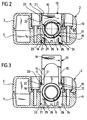
- An insertion opening 11 is provided on the side which is followed by an insertion shaft 12, this insertion opening 11 and the subsequent insertion shaft 12 take a U-shaped securing element 13 with two parallel legs 14, 15 and one connecting them Web 16, which is in the insertion shaft 12 can be inserted that the two legs 14th and 15 the connector 9 between them in immerse a circumferential groove 17 of the connector 9 and thereby facing the connector 9 in the axial direction fix the housing 2.
- the U-shaped securing element 13 is made of an elastic Plastic trained and carries on the free Ends of the legs 14, 15 protruding outwards 18, 19 by elastic bending the legs 14, 15 can be approximated.
- the locking projections 23 and 24 are opposite in that Interior of the insertion shaft 12 projecting wall elements 26, between itself and the wall of the insertion shaft 12 Insertion channels 27, 28 for the free ends of the legs 14 and 15 and the projections 18 and 19 train.
- the circumferential groove 17 is exactly in the area of the insertion shaft 12 of the housing 2, and by inserting the securing element 13 into the Insertion shaft 12 can be the connector 9 in the axial Direction in this position.
- the securing element 13 in the insertion shaft 12 slide the projections 18 and 19 on the Sliding surfaces 21 of the projections, and thereby the legs 14 and 15 with the arranged thereon Projections 18 and 19 elastically moved towards each other, so that the protrusions 18 and 19 on the protrusions 20th can slide past.
- the securing element can this fixing position can be pulled out into a Release position in which the legs 14, 15 from the Circumferential groove 17 are pulled out, but in which the Projections 18 and 19 of the legs 14 and 15 on the steps 22 of the projections 20 strike and thus a complete Pulling out the securing element 13 prevent the insertion shaft 12.
- the securing element 13 is thereby held captive on the housing and can be anywhere between the fixing position and the release position be pushed back and forth.
Landscapes
- Fuses (AREA)
- Toys (AREA)
- Cleaning By Liquid Or Steam (AREA)
- Details Or Accessories Of Spraying Plant Or Apparatus (AREA)
Abstract
Description
- Figur 1:
- eine Längsschnittansicht einer Handspritzpistole mit einem eingesteckten Anschlußstück und mit einem Sicherungselement zur axialen Festlegung des Anschlußstückes in der Handspritzpistole;
- Figur 2:
- eine Schnittansicht längs Linie 2-2 in Figur 1 mit dem Sicherungselement in der Fixierstellung und
- Figur 3:
- eine Ansicht ähnlich Figur 2 mit dem Sicherungselement in der Freigabestellung.
Claims (14)
- Handspritzpistole (1) für ein Hochdruckreinigungsgerät mit einem Gehäuse (2), in welches ein Anschlußstück (9) einer Hochdruckleitung (8) zur Verbindung mit einem Anschluß (10) im Innern des Gehäuses (2) einsteckbar ist, und mit einem seitlich in das Gehäuse (2) einschiebbaren U-förmigen Sicherungselement (13), welches in einer in das Gehäuse (2) eingeschobenen Fixierstellung mit seinen zwei Schenkeln (14, 15) seitliche Rücksprünge des Anschlußstückes (9) hintergreift und dadurch das Anschlußstück (9) im Gehäuse (2) gegen ein Herausziehen sichert, und welches aus dem Gehäuse (2) herausziehbar ist, um das Anschlußstück (9) zum Herausziehen aus dem Gehäuse (2) freizugeben, dadurch gekennzeichnet, daß die Schenkel (14, 15) Sperrglieder (18, 19) tragen, die ein vollständiges Herausziehen des Sicherungselementes (13) aus dem Gehäuse (2) verhindern.
- Einspritzpistole nach Anspruch 1, d durch gekennzeichnet, daß die Sperrglieder Anschläge (18, 19) sind, die an Anschlägen (22) des Gehäuses (2) anschlagen, sobald das Sicherungselement (13) aus einer das Anschlußstück (9) freigebenden Freigabestellung weiter aus dem Gehäuse (2) herausgezogen wird.
- Handspritzpistole nach Anspruch 2, dadurch gekennzeichnet, daß die Anschläge (18, 19) quer zur Verschieberichtung des Sicherungselementes (13) im Gehäuse (2) federnd einschiebbar sind.
- Handspritzpistole nach einem der voranstehenden Ansprüche, dadurch gekennzeichnet, daß die Anschläge am Sicherungselement (13) gebildet werden durch seitliche Vorsprünge (18, 19) an den Außenseiten der Schenkel (14, 15).
- Handspritzpistole nach Anspruch 4, dadurch gekennzeichnet, daß die seitlichen Vorsprünge (18, 19) am freien Ende der Schenkel (14, 15) angeordnet sind.
- Handspritzpistole nach einem der Ansprüche 4 oder 5, dadurch gekennzeichnet, daß die Schenkel (14, 15) federnd gegeneinander drückbar sind.
- Handspritzpistole nach einem der voranstehenden Ansprüche, dadurch gekennzeichnet, daß die Anschläge am Gehäuse (2) gebildet werden durch die eine Einschiebeöffnung (11) für das Sicherungselement (13) umgebende Wand des Gehäuses (2).
- Handspritzpistole nach einem der Ansprüche 1 bis 6, dadurch gekennzeichnet, daß die Anschläge am Gehäuse gebildet werden durch seitliche Vorsprünge (20) in einem sich an eine Einschiebeöffnung (11) für das Sicherungselement (13) anschließenden Aufnahmeschacht (12) für das Sicherungselement (13).
- Handspritzpistole nach Anspruch 8, dadurch gekennzeichnet, daß die Vorsprünge (20) in Einschieberichtung Aufgleitflächen (21) für die Anschläge (18, 19) des Sicherungselements (13) aufweisen.
- Handspritzpistole nach Anspruch 9, dadurch gekennzeichnet, daß die Vorsprünge (20) in Ausschieberichtung stufig ausgebildet sind.
- Handspritzpistole nach einem der Ansprüche 8 bis 10, dadurch gekennzeichnet, daß die Abstände der Vorsprünge (20) der Breite des Sicherungselements (13) entsprechen, die das Sicherungselement (13) im Abstand zu seinen Anschlägen (18, 19) aufweist.
- Handspritzpistole nach einem der Ansprüche 3 bis 11, dadurch gekennzeichnet, daß im Gehäuse (2) Rastvorsprünge (23, 24) angeordnet sind, die die Anschläge (18, 19) des Sicherungselements (13)in der Fixierstellung hintergreifen.
- Randspritzpistole nach Anspruch 12, dadurch gekennzeichnet, daß die Rastvorsprünge (23, 24) beiderseitig Aufgleitflächen (25) für die Anschläge (18, 19) des Sicherungselements (13) aufweisen.
- Handspritzpistole nach einem der Ansprüche 12 oder 13, dadurch gekennzeichnet, daß die Schenkel (14, 15) des Sicherungselementes (13) in der Fixierstellung in Vertiefungen (27, 28) eintauchen, die eine Annäherung der freien Enden der Schenkel (14, 15) begrenzen.
Applications Claiming Priority (2)
| Application Number | Priority Date | Filing Date | Title |
|---|---|---|---|
| DE29916385U DE29916385U1 (de) | 1999-09-17 | 1999-09-17 | Handspritzpistole für ein Hochdruckreinigungsgerät |
| DE29916385U | 1999-09-17 |
Publications (3)
| Publication Number | Publication Date |
|---|---|
| EP1084762A2 true EP1084762A2 (de) | 2001-03-21 |
| EP1084762A3 EP1084762A3 (de) | 2002-05-02 |
| EP1084762B1 EP1084762B1 (de) | 2005-02-02 |
Family
ID=8079058
Family Applications (1)
| Application Number | Title | Priority Date | Filing Date |
|---|---|---|---|
| EP00119952A Expired - Lifetime EP1084762B1 (de) | 1999-09-17 | 2000-09-14 | Handspritzpistole für ein Hochdruckreinigungsgerät |
Country Status (2)
| Country | Link |
|---|---|
| EP (1) | EP1084762B1 (de) |
| DE (2) | DE29916385U1 (de) |
Cited By (1)
| Publication number | Priority date | Publication date | Assignee | Title |
|---|---|---|---|---|
| US20250050369A1 (en) * | 2023-08-10 | 2025-02-13 | Mat Industries, Llc | Flexible stay-in-place blow gun extension |
Families Citing this family (2)
| Publication number | Priority date | Publication date | Assignee | Title |
|---|---|---|---|---|
| DE102006013005A1 (de) * | 2006-03-22 | 2007-09-27 | Alfred Kärcher Gmbh & Co. Kg | Hochdruckspritzpistole |
| CN119158833B (zh) * | 2024-11-20 | 2025-03-04 | 浙江博高机电科技有限公司 | 清洗机 |
Citations (2)
| Publication number | Priority date | Publication date | Assignee | Title |
|---|---|---|---|---|
| DE2720241A1 (de) | 1976-05-10 | 1977-11-24 | Sperry Rand Corp | Einrichtung zur elektrisch isolierten ankopplung eines digitalen datengenerators an eine digitale datenanzeigeeinrichtung |
| EP0885661A2 (de) | 1997-05-22 | 1998-12-23 | Interpump Group S.P.A. | Sprühpistole mit Schnellkupplung |
Family Cites Families (9)
| Publication number | Priority date | Publication date | Assignee | Title |
|---|---|---|---|---|
| DE2542284C3 (de) * | 1975-09-23 | 1981-06-11 | Hermann Hemscheidt Maschinenfabrik Gmbh & Co, 5600 Wuppertal | Mehrfachsteckkupplung |
| GB2074278B (en) * | 1980-04-16 | 1984-02-29 | Chubb Panorama | Fluid conducting spigot and socket connector assembly |
| DE8504133U1 (de) | 1985-02-14 | 1985-05-09 | Gewerkschaft Eisenhütte Westfalia, 4670 Lünen | Kerbkupplungsklammer fuer hydraulische steckkupplungen |
| US4600221A (en) * | 1985-09-30 | 1986-07-15 | Bimba Charles W | Connection system for flexible tubing |
| DE3720241C2 (de) | 1986-09-26 | 1994-09-22 | Wolfgang Suttner | Ventilpistole für ein Hochdruckreinigungsgerät |
| DE3817472A1 (de) | 1988-05-21 | 1989-11-30 | Daimler Benz Ag | Verriegelung fuer eine fluidische steckverbindung |
| FR2649182B1 (fr) * | 1989-07-03 | 1991-10-11 | Chaffoteaux Et Maury | Perfectionnements aux raccords de tuyauteries |
| US5951063A (en) * | 1995-06-07 | 1999-09-14 | Itt Manufacturing Enterprises, Inc. | Quick connector with snap-on retainer having enhanced engagement |
| DE19603506A1 (de) | 1996-02-01 | 1997-06-12 | Fichtel & Sachs Ag | Lösbare Steckverbindung |
-
1999
- 1999-09-17 DE DE29916385U patent/DE29916385U1/de not_active Expired - Lifetime
-
2000
- 2000-09-14 EP EP00119952A patent/EP1084762B1/de not_active Expired - Lifetime
- 2000-09-14 DE DE50009402T patent/DE50009402D1/de not_active Expired - Lifetime
Patent Citations (2)
| Publication number | Priority date | Publication date | Assignee | Title |
|---|---|---|---|---|
| DE2720241A1 (de) | 1976-05-10 | 1977-11-24 | Sperry Rand Corp | Einrichtung zur elektrisch isolierten ankopplung eines digitalen datengenerators an eine digitale datenanzeigeeinrichtung |
| EP0885661A2 (de) | 1997-05-22 | 1998-12-23 | Interpump Group S.P.A. | Sprühpistole mit Schnellkupplung |
Cited By (1)
| Publication number | Priority date | Publication date | Assignee | Title |
|---|---|---|---|---|
| US20250050369A1 (en) * | 2023-08-10 | 2025-02-13 | Mat Industries, Llc | Flexible stay-in-place blow gun extension |
Also Published As
| Publication number | Publication date |
|---|---|
| EP1084762B1 (de) | 2005-02-02 |
| DE29916385U1 (de) | 1999-12-23 |
| DE50009402D1 (de) | 2005-03-10 |
| EP1084762A3 (de) | 2002-05-02 |
Similar Documents
| Publication | Publication Date | Title |
|---|---|---|
| DE69919724T2 (de) | Kupplungsvorrichtung | |
| DE3226571C2 (de) | Verbindungsstück für Schlauchleitungen von Hochdruckreinigungs- und -sprühgeräten | |
| EP1318343B1 (de) | Steckverbindung | |
| EP0057916A2 (de) | Stielbefestigungsvorrichtung, insbesondere für Haus- und Gartengeräte | |
| EP0781386A1 (de) | Anschlussstück für die rohrleitungskupplung eines hochdruckreinigungsgeräts | |
| EP1015804A1 (de) | Anschlussvorrichtung für ein rohr- oder schlauchteil | |
| DE10007204A1 (de) | Drehbarer Absperrhahn für eine Steckkupplung mit abgewinkeltem Anschlußstutzen | |
| EP1969280A1 (de) | Steckteil für steckverbinderanordnung | |
| DE4205142C1 (de) | ||
| DE2822259A1 (de) | Schnellkupplung fuer rohrfoermige leitungen, insbesondere fuer fluessigkeiten | |
| DE4310192A1 (de) | Schnellanschlußkupplung | |
| EP1290370A1 (de) | Lösbare schnellkupplung mit sicherheitsklammer | |
| CH689062A5 (de) | Befestigungskupplung fuer Wellrohre. | |
| DE3246887C2 (de) | Stielbefestigungskupplung, insbesondere für Haus- und Gartengeräte | |
| DE3837492A1 (de) | Loesbare schnell-steckverbindung | |
| EP1084762B1 (de) | Handspritzpistole für ein Hochdruckreinigungsgerät | |
| EP0804970B1 (de) | Handspritzpistole für ein Hochdruckreinigungsgerät | |
| EP3153757B1 (de) | Lösbare steckverbindung für rohrleitungen | |
| DE29505752U1 (de) | Vorrichtung zum Verbinden von Platten mittels Verschraubung | |
| AT502399B1 (de) | Einrichtung zum festlegen eines tür- oder fenstergriffes | |
| DE69600824T2 (de) | Rohrverbindung | |
| DE29514822U1 (de) | Kupplungsteil | |
| DE3442327C1 (de) | Verbindungsstück für Hochdruck-Schläuche | |
| EP1591708B1 (de) | Verbindungselement zum Anschluss eines Schlauchs an eine Molchstation | |
| DE8700415U1 (de) | Rohrverschraubung |
Legal Events
| Date | Code | Title | Description |
|---|---|---|---|
| PUAI | Public reference made under article 153(3) epc to a published international application that has entered the european phase |
Free format text: ORIGINAL CODE: 0009012 |
|
| AK | Designated contracting states |
Kind code of ref document: A2 Designated state(s): DE DK FR GB IT Kind code of ref document: A2 Designated state(s): AT BE CH CY DE DK ES FI FR GB GR IE IT LI LU MC NL PT SE |
|
| AX | Request for extension of the european patent |
Free format text: AL;LT;LV;MK;RO;SI |
|
| PUAL | Search report despatched |
Free format text: ORIGINAL CODE: 0009013 |
|
| AK | Designated contracting states |
Kind code of ref document: A3 Designated state(s): AT BE CH CY DE DK ES FI FR GB GR IE IT LI LU MC NL PT SE |
|
| AX | Request for extension of the european patent |
Free format text: AL;LT;LV;MK;RO;SI |
|
| RIC1 | Information provided on ipc code assigned before grant |
Free format text: 7B 05B 9/01 A, 7B 05B 15/00 B, 7B 08B 3/02 B, 7F 16L 37/14 B |
|
| 17P | Request for examination filed |
Effective date: 20021015 |
|
| AKX | Designation fees paid |
Free format text: DE DK FR GB IT |
|
| RAP1 | Party data changed (applicant data changed or rights of an application transferred) |
Owner name: ALFRED KAERCHER GMBH & CO. KG |
|
| GRAP | Despatch of communication of intention to grant a patent |
Free format text: ORIGINAL CODE: EPIDOSNIGR1 |
|
| GRAS | Grant fee paid |
Free format text: ORIGINAL CODE: EPIDOSNIGR3 |
|
| GRAA | (expected) grant |
Free format text: ORIGINAL CODE: 0009210 |
|
| AK | Designated contracting states |
Kind code of ref document: B1 Designated state(s): DE DK FR GB IT |
|
| PG25 | Lapsed in a contracting state [announced via postgrant information from national office to epo] |
Ref country code: GB Free format text: LAPSE BECAUSE OF FAILURE TO SUBMIT A TRANSLATION OF THE DESCRIPTION OR TO PAY THE FEE WITHIN THE PRESCRIBED TIME-LIMIT Effective date: 20050202 Ref country code: FR Free format text: LAPSE BECAUSE OF NON-PAYMENT OF DUE FEES Effective date: 20050202 |
|
| REG | Reference to a national code |
Ref country code: GB Ref legal event code: FG4D Free format text: NOT ENGLISH |
|
| REG | Reference to a national code |
Ref country code: IE Ref legal event code: FG4D Free format text: GERMAN |
|
| REF | Corresponds to: |
Ref document number: 50009402 Country of ref document: DE Date of ref document: 20050310 Kind code of ref document: P |
|
| PG25 | Lapsed in a contracting state [announced via postgrant information from national office to epo] |
Ref country code: DK Free format text: LAPSE BECAUSE OF FAILURE TO SUBMIT A TRANSLATION OF THE DESCRIPTION OR TO PAY THE FEE WITHIN THE PRESCRIBED TIME-LIMIT Effective date: 20050502 |
|
| GBV | Gb: ep patent (uk) treated as always having been void in accordance with gb section 77(7)/1977 [no translation filed] |
Effective date: 20050202 |
|
| PLBE | No opposition filed within time limit |
Free format text: ORIGINAL CODE: 0009261 |
|
| STAA | Information on the status of an ep patent application or granted ep patent |
Free format text: STATUS: NO OPPOSITION FILED WITHIN TIME LIMIT |
|
| 26N | No opposition filed |
Effective date: 20051103 |
|
| EN | Fr: translation not filed | ||
| PGFP | Annual fee paid to national office [announced via postgrant information from national office to epo] |
Ref country code: IT Payment date: 20130910 Year of fee payment: 14 |
|
| PGFP | Annual fee paid to national office [announced via postgrant information from national office to epo] |
Ref country code: DE Payment date: 20131026 Year of fee payment: 14 |
|
| REG | Reference to a national code |
Ref country code: DE Ref legal event code: R119 Ref document number: 50009402 Country of ref document: DE |
|
| PG25 | Lapsed in a contracting state [announced via postgrant information from national office to epo] |
Ref country code: DE Free format text: LAPSE BECAUSE OF NON-PAYMENT OF DUE FEES Effective date: 20150401 |
|
| PG25 | Lapsed in a contracting state [announced via postgrant information from national office to epo] |
Ref country code: IT Free format text: LAPSE BECAUSE OF NON-PAYMENT OF DUE FEES Effective date: 20140914 |