EP1084643A2 - Flächenhaftverschluss aus Kunststoff - Google Patents
Flächenhaftverschluss aus Kunststoff Download PDFInfo
- Publication number
- EP1084643A2 EP1084643A2 EP00119322A EP00119322A EP1084643A2 EP 1084643 A2 EP1084643 A2 EP 1084643A2 EP 00119322 A EP00119322 A EP 00119322A EP 00119322 A EP00119322 A EP 00119322A EP 1084643 A2 EP1084643 A2 EP 1084643A2
- Authority
- EP
- European Patent Office
- Prior art keywords
- flat plate
- fastener
- engaging
- plate portion
- rear side
- Prior art date
- Legal status (The legal status is an assumption and is not a legal conclusion. Google has not performed a legal analysis and makes no representation as to the accuracy of the status listed.)
- Withdrawn
Links
Images


Classifications
-
- A—HUMAN NECESSITIES
- A44—HABERDASHERY; JEWELLERY
- A44B—BUTTONS, PINS, BUCKLES, SLIDE FASTENERS, OR THE LIKE
- A44B18/00—Fasteners of the touch-and-close type; Making such fasteners
-
- A—HUMAN NECESSITIES
- A44—HABERDASHERY; JEWELLERY
- A44B—BUTTONS, PINS, BUCKLES, SLIDE FASTENERS, OR THE LIKE
- A44B17/00—Press-button or snap fasteners
- A44B17/0029—Press-button fasteners made of plastics
-
- Y—GENERAL TAGGING OF NEW TECHNOLOGICAL DEVELOPMENTS; GENERAL TAGGING OF CROSS-SECTIONAL TECHNOLOGIES SPANNING OVER SEVERAL SECTIONS OF THE IPC; TECHNICAL SUBJECTS COVERED BY FORMER USPC CROSS-REFERENCE ART COLLECTIONS [XRACs] AND DIGESTS
- Y10—TECHNICAL SUBJECTS COVERED BY FORMER USPC
- Y10T—TECHNICAL SUBJECTS COVERED BY FORMER US CLASSIFICATION
- Y10T24/00—Buckles, buttons, clasps, etc.
- Y10T24/27—Buckles, buttons, clasps, etc. including readily dissociable fastener having numerous, protruding, unitary filaments randomly interlocking with, and simultaneously moving towards, mating structure [e.g., hook-loop type fastener]
- Y10T24/2708—Combined with diverse fastener
-
- Y—GENERAL TAGGING OF NEW TECHNOLOGICAL DEVELOPMENTS; GENERAL TAGGING OF CROSS-SECTIONAL TECHNOLOGIES SPANNING OVER SEVERAL SECTIONS OF THE IPC; TECHNICAL SUBJECTS COVERED BY FORMER USPC CROSS-REFERENCE ART COLLECTIONS [XRACs] AND DIGESTS
- Y10—TECHNICAL SUBJECTS COVERED BY FORMER USPC
- Y10T—TECHNICAL SUBJECTS COVERED BY FORMER US CLASSIFICATION
- Y10T24/00—Buckles, buttons, clasps, etc.
- Y10T24/27—Buckles, buttons, clasps, etc. including readily dissociable fastener having numerous, protruding, unitary filaments randomly interlocking with, and simultaneously moving towards, mating structure [e.g., hook-loop type fastener]
- Y10T24/2725—Buckles, buttons, clasps, etc. including readily dissociable fastener having numerous, protruding, unitary filaments randomly interlocking with, and simultaneously moving towards, mating structure [e.g., hook-loop type fastener] with feature facilitating, enhancing, or causing attachment of filament mounting surface to support therefor
-
- Y—GENERAL TAGGING OF NEW TECHNOLOGICAL DEVELOPMENTS; GENERAL TAGGING OF CROSS-SECTIONAL TECHNOLOGIES SPANNING OVER SEVERAL SECTIONS OF THE IPC; TECHNICAL SUBJECTS COVERED BY FORMER USPC CROSS-REFERENCE ART COLLECTIONS [XRACs] AND DIGESTS
- Y10—TECHNICAL SUBJECTS COVERED BY FORMER USPC
- Y10T—TECHNICAL SUBJECTS COVERED BY FORMER US CLASSIFICATION
- Y10T24/00—Buckles, buttons, clasps, etc.
- Y10T24/36—Button with fastener
- Y10T24/3651—Separable
-
- Y—GENERAL TAGGING OF NEW TECHNOLOGICAL DEVELOPMENTS; GENERAL TAGGING OF CROSS-SECTIONAL TECHNOLOGIES SPANNING OVER SEVERAL SECTIONS OF THE IPC; TECHNICAL SUBJECTS COVERED BY FORMER USPC CROSS-REFERENCE ART COLLECTIONS [XRACs] AND DIGESTS
- Y10—TECHNICAL SUBJECTS COVERED BY FORMER USPC
- Y10T—TECHNICAL SUBJECTS COVERED BY FORMER US CLASSIFICATION
- Y10T24/00—Buckles, buttons, clasps, etc.
- Y10T24/36—Button with fastener
- Y10T24/3694—Ornamental type
Definitions
- the present invention relates to a synthetic resin opening and closing press fastener employed in place of a conventional snap button or a general button.
- the fastener is composed of an integrally molded product having substantially U Shape cross section, in which one end of each of thermoplastic resin based flat plate portions of the same shape substantially parallel to each other are connected by means of a connecting portion.
- a number of male engaging elements are molded to stand on one flat plate portion surface sandwiching said connecting portion, and a pinch piece protruded from the connecting portion outwardly is molded in parallel to the flat plate portions.
- a groove shaped sewing line is formed along the entire peripheral edge of each of the two flat plate portion surfaces.
- each flat plate portion in the opening and closing press fastener, it is required to mold the thickness of each flat plate portion as thinly as possible in order to ensure the flexibility of clothes or the like.
- a further thin sewing line is formed along the entire peripheral edge, and thus, the fastener is easily broken at that portion.
- thinning the thickness of the flat plate portion there is a limitation to thinning the thickness of the flat plate portion.
- the sewing line formed at both flat plate portions is often shifted, making it difficult to ensure exact sewing along the sewing line.
- this modified opening and closing press fastener has two portions, i.e., first and second thermoplastic synthetic resin flat plate portions substantially parallel to each other, one end edge being connected to another via the connecting portion, and is integrally molded so that the cross section is formed in a substantially J shape.
- a number of engaging elements are formed to stand on a surface of the first flat plate portion having a large surface area, and a groove shaped sewing line is formed along its full peripheral edge.
- a groove shaped sewing line is formed corresponding to part of the sewing line formed at the first flat plate portion, ends of which are opened, on the surface of the second flat plate portion having a small surface area.
- one of the two flat plate portions connected each other via the connecting portion is formed to be short in length, and thus, the end edge of clothes can be easily inserted between the two flat plate portions without opening two flat plate portions during sewing.
- the groove shaped sewing line is formed along the entire peripheral edge of the first flat plate portion having the large surface area, at the other second flat plate portion with its small surface area, the transverse U shaped groove shaped sewing line of which the ends at an end edge opposite to the connecting portion are opened is merely formed at a corresponding position so as to be partially superimposed with the sewing line formed in the first flat plate portion.
- the first flat plate portion having large surface area is arranged on the rear side at the fastener attaching site of clothes, and the second flat plate portion having small surface area is arranged on the front side of clothes.
- the rigidity at the attaching site is substantially eliminated, and the visibility is increased.
- the thickness of the flat plate portion is somewhat increased, required flexibility can be ensured, and opening operation of the fastener is performed smoothly.
- the fixing fastener is attached to the attached body by means of sewing.
- the sewing work is cumbersome and once the fixing fastener is attached to the attached body, the fixing fastener cannot be removed from the attached body unless the sewing yarn is cut, and the-fastener cannot be replaced easily.
- the required minimum thickness is provided at the first and second flat plate portions in order to prevent the strength from being lowered due to sewing. In view of flexibility, the rigid feeling cannot be eliminated.
- a synthetic resin opening and closing press fastener comprising: a front side flat plate portion and a rear side flat plate portion which are to be attached to an end edge of a flat plate shaped attached body, a positioning portion of the end edge of the attached body being provided on a part of the press fastener; and a number of engaging elements of a surface fastener on a rear side, wherein the opening and closing press fastener is attached to the attached body by means of a synthetic resin pin member having an engaging head at least at one end.
- a conventional press fastener of this type has been attached to its attached body by means of sewing using the sewing yarn.
- the present invention is primarily featured in that the press fastener Is attached to the attached body by means of a synthetic resin pin member by a simple operation. That is, when the fastener attaching end edge of the attached body is inserted from an opening end of the front and rear side flat plate portions of the press fastener, and the end edge abuts against a connecting portion that is a positioning portion, an engaging pin connects both of the flat plate portions via the attached body.
- the engaging head formed at a free end of the pin is removably attached to at least one engaging portion of both of the flat plate portions, and thus the attaching is completed.
- the front and rear side flat plate portions are integrally molded via the positioning portion.
- the front and rear side flat plate portions are separate from each other.
- the flat plate portion of each of the front and rear sides have to have the same color.
- each flat plate portion can be arbitrarily selected, and a variety of uses can be achieved in view of appearance and design in accordance with preference.
- the pin member is molded to protrude integrally with an inner face of the front side flat plate portion or the rear side flat plate portion toward an inner surface of the flat plate portion of the counterpart.
- a surface area of the front side flat plate portion is set to be smaller than that of the rear side flat plate portion, and the pin member is molded integrally with a rear face of the rear side flat plate portion at a position out of the front side flat plate portion toward the front side.
- the press fastener When a fastener attaching end edge such as clothes is inserted between the flat plate portions on the front and rear surface sides of the press fastener by employing the aforementioned construction, the press fastener is formed to have substantial J shape in section, and the fastener attaching end edge such as clothes can be easily inserted without widening its opening end. Moreover, its attaching end edge is abutted against the positioning portion, whereby the attaching condition and position of the press fastener is automatically determined, and thus, the press fastener can be attached neatly. Further, a pinch piece extending outwardly from the positioning portion is provided, thus improving the durability and opening and closing operability of the press fastener.
- the pin member is separate from the front and rear side flat plate portions, and an engaging head is provided at both ends thereof.
- the engaging head of both ends may be formed from the start. It may be formed at one end. While the fastener attaching end edge of the attached body is sandwiched between the front and rear side flat plate portions of the press fastener, an end on one side of the pin member on which its engaging head is not formed is inserted through the front and rear side flat plate portions via the attached body, and thereafter, the engaging head may be formed by deforming the end to be softened by heating or ultrasound.
- the number of the engaging elements are formed on the surface of the rear side flat plate portion.
- a flat plate shaped press fastening portion substantially parallel to the front and rear side flat plate portions extending from the positioning portion to the outside is provided to the fastener, and a number of the engaging elements are formed on the rear side of the press fastening portion.
- the opening operation force acting to an engagement face directly acts to the attached body sandwiched between both of the flat plate portions on the front and rear sides.
- the attached body may be damaged.
- a majority of the force caused during opening operation acts only to the press fastening portion, and the damage of the attached body due to the opening operation is reduced, and the durability is improved.
- the engaging element is made of synthetic resin, and is molded integrally with the opening and closing press fastener, and high productivity and low manufacturing cost can be achieved.
- the rigidity of the male engaging elements is felt, and slight noise occurs during release from the engaging member of the counterpart.
- the engaging elements are obtained by cutting part of a loop made of a monofilament woven and knitted at the foundation structure during weaving and knitting, and the foundation structure is securely fixed to the opening and closing press fastener.
- the above described male engaging elements of the opening and closing press fastener are composed of a monofilament woven or knitted in the woven fabrics or knitted fabrics, at the time of weaving or knitting.
- the cost per product unit of the surface fastener member is increased, and further, the number of processes for bonding the surface fastener to a predetermined position of the press fastener is increased.
- the manufacturing cost is inevitably increased.
- FIG. 1 is a perspective view showing a state before attaching an opening and closing press fastener according to a first embodiment of the present invention and an end edge attaching portion such as clothes being an attached body.
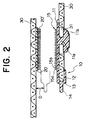
- FIG. 2 is a sectional view showing a relationship between an attaching state of the press fastener and a female surface fastener member of the counterpart, and
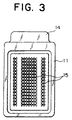
- FIG. 3 is a plan view showing the press fastener seen from a rear side.
- FIG. 4 is a front view showing an example of clothes to which the press fastener is attached.
- An opening and closing press fastener 10 has a substantially rectangle shaped rear side flat plate portion 11; a rectangle shaped front side flat plate portion 12 having a long side which is as long as a short side of the rear side flat plate portion 11 and consisting of a short side having a length which is substantially 1/5 of a long side of the rear side flat plate portion 11; and a connecting portion 13 for connecting the short side end edge of the rear side plate portion 11 to the long side end edge of the front side flat plate portion 12 in parallel to each other with a predetermined interval, and the entire side face shape is formed in a substantially J shape.
- the connecting portion 13 constitutes a positioning portion of the present invention for positioning the attaching end edge of an attached body 30 such as clothes.
- a pinch piece 14 parallel to both of the flat plate portions 11 and 12 is protruded outwardly at this connecting portion 13.
- the interval between the rear side and front side flat plate portions 11 and 12 is arbitrarily determined depending on the thickness of the attaching portion of the attached body 30 to which the press fastener 10 of the present invention is attached.
- the engaging element 15 in this embodiment is formed in a hook shape having a rising portion 15a standing from the rear side flat plate portion 11 and an engaging portion 15b extending outwardly and curved from a tip end of the rising portion 15a, as shown in FIG. 2.
- all engaging portions 15b extend in the same directions.
- each of the hook shaped engaging elements 15 is formed such that tip end of the engaging portion 15b faces in a direction opposite to the protrusion direction of the pinch piece 14.
- a strength of engagement with a surface fastener member 20 of the counterpart having a number of loops 20' is the strongest in a direction opposite to the extension direction of the curved engaging portion 15b.
- the extension direction of the engaging portion 15b can be oriented in an opposite direction in the adjacent arrays of each of the hook shaped engaging elements 15. In such a case, directivity in the strength of engagement with the surface fastener member 20 of the counterpart is eliminated.
- pin members each having a disk shaped engaging head 11b are protruded and molded integrally at its tip end via a stem 11a of a rectangular cross section. It is preferable that a logo mark or a variety of decorative patterns is formed at an end face of this engaging head 11b. Although it is desirable that these patterns are formed at the same as when they are molded, it is possible to form them after they have been molded by a variety of welders or prints. In addition, a decorative pattern can be formed similarly on the surface of the front side flat plate portion 12 (front face of the press fastener).
- a slit shaped engaging hole 31 for engaging the engaging head 11b is formed at the press fastener attaching portion of the attached body 30 such as clothes.
- the opening and closing press fastener 10 can be molded simply in a single process by means of injection molding, for example. That is, injection molding can be easily done by means of an injection mold in which cavities for molding the rear side flat plate portion 11, the number of engaging elements 15, the connecting portion 13; the stem 11a, and a part of the engagement head are formed at a movable die (not shown) by employing a split mold, and an insert mold is combined in a mating fixed mold, so that cavities for molding the external shape and decorative pattern of the front side flat plate portion 12, part of the connecting portion 13 and the disk shaped engaging head 11b are formed.
- the cavities of the hook shaped engaging elements 15 cannot be engraved on a single mold surface because of its shape.
- the entire or partial shape of the cavity is formed at the end face of a plurality of thin plate materials, and is formed by laminating them in combination.
- the elements can be directly pulled out from the hook shaped cavities by a releasing member such as an ejector pin (not shown).
- a plurality of the thin plate materials are spaced by proper means in the plate thickness direction, whereby they can be easily separated.
- the pinch piece 14 is arranged at the outside of clothes, and the rear side at which the engaging elements 15 are protruded is provided at the inside of the clothes.
- an upper front end edge 30a at a fly of a ski wear 30 as shown in FIG. 4 is pinched with both flat plate portions 11 and 12, and the engaging head 11b is engaged with the slit shaped engaging hole 31 to be temporarily fixed.
- the female surface fastener member 20 of the counterpart having the number of loops 20' engaged with or disengaged from the fastener 10 corresponding to the attaching position of the press fastener 10 is attached by means of sewing, bonding or the like.
- the cross section is formed in the substantial J shape.
- the upper front end edge 30a of clothes or the like can be easily inserted without widening its opening end.
- its insert end edge is abutted against the internal wall face of the connecting portion 13 that is a positioning portion, whereby the condition and position of attachment of the press fastener 10 is automatically determined, and thus, the press fastener 10 can be attached neatly.
- the pinch piece 14 extended outwardly from the connecting portion is provided, thus ensuring durability and opening/closing operability.
- the sectional rectangle shaped stem 11a having a long side portion along the longitudinal direction of the engaging hole 31 of the attached body 30 exists between the disk shaped engaging head 11b and the inner face of the rear side flat plate portion 11.
- the press fastener 10 does not turn in the engaging hole 31 together with the connecting portion 13. Accordingly, the press fastener 10 does not slip off from the attached body 30.
- the press fastener 10 can be easily removed in the same manner as when a general button is removed from a button hole.
- the press fastener 10 having preferable color and pattern of the wearer's preference can be freely selected at the time of wearing, and moreover, the fastener can be arbitrarily replaced with another one. In addition, the press fastener can be removed for washing or ironing.
- FIG. 4 shows an appearance of the ski wear in which the opening and closing press fastener 10 of the present invention and the surface fastener member of the counterpart (not shown) are attached.
- the above press fastener 10 of the embodiment is pressed toward the surface fastener member 20 of the counterpart, both of them are easily engaged with each other, and the fly shown in the figure is closed.
- the engaging portions 15b of all the hook shaped engaging elements 15 are oriented in opening direction.
- the loops 20' act to the shear direction of the rising portion 15a of the hook shaped engaging elements 15, i.e., to the direction in which the engaging strength is the greatest.
- the fly is not opened easily.
- a gap D is formed between the pinch piece 14 of the press fastener 10 and the lower front portion of the fly.
- the hook shaped engaging element 15 may be formed not integrally with the surface of the rear side flat plate portion 11.
- a common fiber based surface fastener having its external shape similar to the front side flat plate portion 11 and having hooks of a general monofilament on the surface of the base cloth of a knitted material may be bonded onto a flat face of the rear side flat plate portion 11 with an adhesive, for example.
- FIG. 5 and FIG. 6 are views each showing an attaching state of a press fastener 110 that is a second embodiment of the present invention.
- a rear side flat plate portion 111 and a front side flat plate portion 112 have the same rectangular shape.
- a connecting portion 113 serving as a positioning portion for connecting one side ends of the portions 111 and 112 has an arc shaped cross section.
- a flat plate shaped pinch piece 114 is extended outwardly linearly at the center of the connecting portion 113.
- a number of hook shaped engaging elements 115 are molded integrally with the surface (rear face of the fastener 110) of the rear side flat plate portion 111.
- Two pin engaging holes 111a and 111b are formed to penetrate with predetermined intervals in the longitudinal direction at the center in the widthwise direction of the rear side flat plate portion 111.
- two engaging pins 112a and 112b having flange shaped engaging heads 112a' and 112b' at their tip ends are protruded to the rear side.
- pin insertion through holes 131a and 131b through which the engaging pins 112a and 112b are penetrated when the fastener attaching edge portion is sandwiched with the flat plate portions 111 and 112 on the front and rear sides, are formed at positions corresponding to the pin engaging holes 111a and 111b and the engaging pins 112a and 112b.
- the press fastener 100 of this embodiment is bent in the substantial U shape, and the attached body 130 is inserted from the opening end of the fastener 100 until the end edge of the attached body 130 abuts against the bottom face of the connecting portion 113. Then, the flat plate portions 111 and 112 at the front and rear sides are pressed toward the mutually opposite face with fingertips or jigs.
- each of the engaging pins 112a and 112b are inserted into respective pin engaging holes 111a and 111b of the rear side flat plate portion 111 via the corresponding pin insertion through holes 131a and 131b, and each of the engaging heads 112a' and 112b' are resiliently deformed to be engaged with each of the pin engaging holes 111a and 111b.
- the press fastener 110 is removed from the attached body 130, the above steps may be reversed. In this way, in this embodiment, the press fastener 110 can be easily attached to and removed from the attached body 130 with one touch operation.
- the hook directions of the hook shaped engaging elements are not necessarily coincident with each other as in the above embodiment.
- the hook directions of the hook shaped engaging elements 115 arranged in the adjacent rows may be oriented in an opposite direction to each other. With such arrangement of the elements, necessary engagement force can be ensured in any direction at the fly.
- a general fiber surface fastener having its external shape similar to the rear side flat plate portion 111 and having the aforementioned monofilament without molding the hook shaped engaging elements 115 integrally with the surface of the rear side flat plate portion 111 may be bonded integrally with the flat face of the rear side flat plate portion 111 with an adhesive.
- the rear side flat plate portion 111 and the front side flat plate portion 112 are molded in its exploded state via the connecting portion 113. Therefore, in this case, in order to facilitate bending along the boundary between both of the flat plate portions 111 and 112 of the front and rear sides and the connecting portion 113, a groove for bending, i.e., a thin portion (not shown) may be formed.
- FIG. 7 shows a modification of the second embodiment.
- this modification is greatly different from the foregoing embodiment in that the rear side flat plate portion 211 and the front side flat plate portion 212 are molded separately.
- the connecting portion 213, pinch piece 214, and hook shaped engaging elements 215 are molded integrally with the rear side flat plate portion 211.
- two engaging pins 212a and 212b are protruded at the rear side surface of the front side flat plate portion 212.
- two pin engaging holes 211a and 211b are formed at the rear side flat plate portion 211.
- each of the engaging pins 212a and 212b is formed to have the flange shaped engaging heads 212a' and 212b' at their tip ends from the first.
- the engaging heads 212a' and 212b' are not molded during molding, and the through holes of the engaging pins 212a and 212b are not formed at an attached body 230.
- the fastener attaching end edge of the attached body 230 is inserted from the opening end of each of the flat plate portions 211 and 212 on the front and rear sides to be abutted against the inner face of the connecting portion 213. Then, the tip ends of the engaging pins 212a and 212b are inserted sequentially into the attached body 230 and the pin engaging hole 212b of the rear side flat plate portion 211.
- the lengths of the engaging pins 212a and 212b are set to be equal to the length enough for extending to the outside from the pin engaging holes 211a and 211b of the rear side flat plate portion 211, and their tip ends are sharply formed.
- the tip ends of the engaging pins 212a and 212b are formed to be sharp, and thus, the attached body 230 such as clothes can be pierced by their tip end. In this modification, no pin insertion through hole is formed at the attached body 230.
- the tip ends of the engaging pins 212a and 212b can be pierced into the attached body 230. Then, the engaging pins 212a and 212b are inserted sequentially into the attached body 230 and the pin engaging holes 211a and 211b of the rear side flat plate portion 211. Thereafter, the sharp tip ends of the engaging pins 212a and 212b are pressed while they are softened by heating or ultrasound. As indicated by the phantom line shown in the figure, the flange shaped engaging heads 212a' and 212b' are formed, and the press fastener 210 is attached to the temporarily fastened attached body 230.
- each of the flat plate portions 211 and 212 with their different colors or shapes on the front and rear sides can be variously combined according to the colors of the front and rear sides of clothes, and a variety of appearances and designs can be achieved.
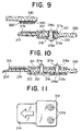
- FIG. 8 and FIG. 9 each show a third embodiment of the present invention, wherein one end of the rectangle shaped rear side flat plate portion 311 is connected to one end of the front side flat plate portion 312 to be parallel to each other via a connecting portion 313. From the center of the connecting portion 313, a rectangular plate shaped press fastening portion 314 with its same width and length as each of the flat plate portions 311 and 312 is extended to the outside parallel to each of the flat plate portions 311 and 312.
- an engaging pin 316 is molded independently of the front and rear side flat plate portions 311 and 312 and the connecting portion 313.
- the pin engaging holes 311a and 312a are formed respectively at the center of the flat plate portions 311 and 312 on the front and rear sides.
- a number of hook shaped engaging elements 315 is formed to be protruded on the rear face of the rectangular plate shaped press fastening portion 314, and a logo mark or various patterns and the like are formed on its front face.
- a pin insertion through hole 331 is formed at the fastener attaching end edge of the attached body 330 such as clothes.
- Engaging heads 316a and 316b formed at both ends of the engaging pin 316 with the pin 316 being sandwiched between both of the flat plate portions 311 and 312 on the front and rear sides are engaged with the respective engaging holes 311a and 312a via the pin insertion through holes 331.
- the engaging head 316b arranged on the front side is shaped in the same way as the general button. Various patterns are formed on its surface. The size of the head 316b is greater than that of the head 316a arranged on the rear side.
- the engaging head 316a arranged on the rear side is formed in a flange shape at the tip end of the engaging pin 316, and is engaged to be resiliently deformable relatively with respect to the pin engaging hole 311a on the rear side.
- the pin engaging hole 311a is divided into a short diameter portion and a long diameter portion via a stepped portion, and the engaging head 316a is engaged with the short diameter portion.
- the attaching end edge of the attached body 330 is inserted from the opening end of each of the flat plate portions 311 and 312 on the front and rear sides of the press fastener 310 until the end edge of the attached body 330 is abutted against the bottom face of the connecting portion 313. Then, the small diameter engaging head 316a is inserted sequentially into the pin engaging hole 312a of the front side flat plate portion 312, the pin insertion through hole 331 of the attached body 330, and the pin engaging hole 311a of the rear side flat plate portion 311 so as to finally engage with the pin engaging hole 311a.
- the press fastener 310 When the press fastener 310 is removed from the attached body 330, the above steps may be reversed. In this way, in this embodiment, the press fastener 310 can be easily attached to or removed from the attached body 330 by inserting and removing operations of the engaging pin 316.
- the engagement and disengagement with the engaging portion of the surface fastener of the counterpart is accomplished by means of a number of hook shaped engaging elements 315 formed on the rear face of the rectangle shaped plate shaped press fastener 314. That is, each of the flat plate portions 311 and 312 on the front and rear sides attached so as to sandwich the attached body 330 is not engaged with the engaging portion of the surface fastener of the counterpart by being pressed via the attached body 330. Instead, the rectangle shaped press fastening portion 314 is engaged by being directly pressed, and thus, reliable engagement can be obtained without pressing so strongly.
- FIG. 10 shows a first modification of the third embodiment.
- the small diameter engaging head 316a is formed from the engaging pin 316 in the third embodiment.
- the pin engaging holes 311a and 312b through which two engaging pins 316 and 316 are inserted are formed with predetermined intervals in a direction of insertion of the flat plate portions 311 and 312 with respect to the attached body 330.
- the through hole of the engaging pin 316 is not formed at the attached body 330.
- the fastener attaching end edge of the attached body 330 is inserted from the opening ends of both of the flat plate portions 311 and 312 on the front and rear sides to abut against the inner face of the connecting portion 313. Then, the tip ends of the engaging pins 316, 316 are inserted sequentially into the pin engaging holes 312a of the front side flat plate portion 312, the attached body 330, and the pin engaging holes 311a of the rear side flat plate portion 311. The tip end of the engaging pin 316 is formed sharply.
- the tip end can be pierced into the attached body 330 such as clothes so that the pin insertion through hole is not formed at the attached body 330.
- the tongue piece shaped pinch piece 314' extends at the outside end edge of the press fastening portion 314, and the woven or knitted fiber female surface fastener having the hook shaped engaging elements 315 of monofilament is bonded to the rear face of the press fastening portion 314 by means of an adhesive.
- FIG. 11 shows a further modification of the press fastener 310 shown in FIG. 10.
- two pin engaging holes 311a and 312a formed at the flat plate portions 311 and 312 on the front and rear sides are formed with predetermined intervals in a direction of insertion of the attached body 330 into the press fastener 310 as described above.
- these two holes are formed in parallel to the connecting portion 313.
Landscapes
- Slide Fasteners, Snap Fasteners, And Hook Fasteners (AREA)
- Connection Of Plates (AREA)
Applications Claiming Priority (2)
| Application Number | Priority Date | Filing Date | Title |
|---|---|---|---|
| JP26161599A JP2001078810A (ja) | 1999-09-16 | 1999-09-16 | 合成樹脂製の開閉用押圧止具 |
| JP26161599 | 1999-09-16 |
Publications (2)
| Publication Number | Publication Date |
|---|---|
| EP1084643A2 true EP1084643A2 (de) | 2001-03-21 |
| EP1084643A3 EP1084643A3 (de) | 2001-11-07 |
Family
ID=17364372
Family Applications (1)
| Application Number | Title | Priority Date | Filing Date |
|---|---|---|---|
| EP00119322A Withdrawn EP1084643A3 (de) | 1999-09-16 | 2000-09-06 | Flächenhaftverschluss aus Kunststoff |
Country Status (5)
| Country | Link |
|---|---|
| US (1) | US6430786B1 (de) |
| EP (1) | EP1084643A3 (de) |
| JP (1) | JP2001078810A (de) |
| CN (1) | CN1288701A (de) |
| TW (1) | TW489607U (de) |
Cited By (1)
| Publication number | Priority date | Publication date | Assignee | Title |
|---|---|---|---|---|
| WO2003073883A1 (en) * | 2002-03-06 | 2003-09-12 | Ykk Corporation | Male fixing member of hook-and loop fastener, and sheet product with the fixing member |
Families Citing this family (11)
| Publication number | Priority date | Publication date | Assignee | Title |
|---|---|---|---|---|
| US20040139585A1 (en) * | 2002-12-26 | 2004-07-22 | Mcvicker Henry J. | Fastening kit and injection molded fastening article for use in such a kit |
| US7254874B2 (en) * | 2004-03-10 | 2007-08-14 | Leonard Arnold Duffy | Molded surface fasteners and attachment methods |
| US7950114B2 (en) * | 2004-03-10 | 2011-05-31 | Leonard Arnold Duffy | Self-adhering device and method |
| CN101513295B (zh) * | 2009-03-10 | 2012-01-04 | 立兆股份有限公司 | 一种黏带扣及其制造方法 |
| FR2965670B1 (fr) * | 2010-09-30 | 2012-10-12 | Airbus Operations Sas | Dispositif de fixation de cables |
| US8726470B2 (en) * | 2011-10-30 | 2014-05-20 | Ervin Hoffman | Clothing fastening system |
| JP6002562B2 (ja) * | 2012-12-05 | 2016-10-05 | 横浜ゴム株式会社 | 面ファスナー付き空気入りタイヤ及びその製造方法 |
| US9474338B2 (en) * | 2013-10-11 | 2016-10-25 | Aplix | Fastener |
| US10188179B2 (en) * | 2013-10-11 | 2019-01-29 | Aplix | Fastener |
| US20150216266A1 (en) * | 2014-02-04 | 2015-08-06 | Brent Franklin | Button replacement |
| CN108056537A (zh) * | 2018-01-17 | 2018-05-22 | 嘉善长强服装辅料厂(普通合伙) | 一种纽扣及其使用方法 |
Family Cites Families (13)
| Publication number | Priority date | Publication date | Assignee | Title |
|---|---|---|---|---|
| US2748517A (en) * | 1953-09-03 | 1956-06-05 | Harriett L Berkis | Removable decorations for clothing |
| US3031730A (en) * | 1958-09-26 | 1962-05-01 | Louis H Morin | Burr-type closure or coupling element |
| US3094757A (en) * | 1961-05-24 | 1963-06-25 | Scovill Manufacturing Co | Fastener means |
| US3405408A (en) * | 1965-12-20 | 1968-10-15 | James H. Baker | Tie holder |
| US3403429A (en) * | 1966-11-09 | 1968-10-01 | Smith George Walter Henry | Strip fastening means |
| US3851357A (en) * | 1971-02-03 | 1974-12-03 | American Velcro Inc | Fastener |
| US4541154A (en) * | 1981-11-12 | 1985-09-17 | Yoshida Kogyo K.K. | Hooked fabric fastener tape |
| US5048160A (en) * | 1990-04-09 | 1991-09-17 | Goodrich Lewis S | Button replacement device |
| US5231738A (en) * | 1991-12-12 | 1993-08-03 | Kuraray Co., Ltd. | Mixed hook/loop separable fastener and process for its production |
| US5282616A (en) * | 1993-01-13 | 1994-02-01 | Stacavich Notaro Marylou I | Golf ball marker |
| JPH0975113A (ja) * | 1995-09-14 | 1997-03-25 | Ykk Corp | 開閉用押圧止具 |
| JPH1193007A (ja) * | 1997-09-12 | 1999-04-06 | Ykk Corp | シート状物に対する係着片の取付構造 |
| JP3474791B2 (ja) | 1998-12-24 | 2003-12-08 | Ykk株式会社 | 開閉用押圧止具 |
-
1999
- 1999-09-16 JP JP26161599A patent/JP2001078810A/ja active Pending
-
2000
- 2000-09-06 EP EP00119322A patent/EP1084643A3/de not_active Withdrawn
- 2000-09-07 TW TW090223858U patent/TW489607U/zh unknown
- 2000-09-15 CN CN00127058A patent/CN1288701A/zh active Pending
- 2000-09-15 US US09/662,841 patent/US6430786B1/en not_active Expired - Fee Related
Cited By (1)
| Publication number | Priority date | Publication date | Assignee | Title |
|---|---|---|---|---|
| WO2003073883A1 (en) * | 2002-03-06 | 2003-09-12 | Ykk Corporation | Male fixing member of hook-and loop fastener, and sheet product with the fixing member |
Also Published As
| Publication number | Publication date |
|---|---|
| CN1288701A (zh) | 2001-03-28 |
| EP1084643A3 (de) | 2001-11-07 |
| TW489607U (en) | 2002-06-01 |
| JP2001078810A (ja) | 2001-03-27 |
| US6430786B1 (en) | 2002-08-13 |
Similar Documents
| Publication | Publication Date | Title |
|---|---|---|
| US6430786B1 (en) | Synthetic resin opening and closing press fastener | |
| JP2886455B2 (ja) | 一体成形面ファスナーの係着片構造 | |
| US5655268A (en) | Button-substitute fastening device | |
| US20030115727A1 (en) | Fastener for brassier or brassier-like garment, a manufacturing method thereof and a brassier or brassier-like garment using such a fastener | |
| US6442808B2 (en) | Button fastener | |
| US20080034560A1 (en) | Self-adhering device and method | |
| JP4072953B2 (ja) | 開離嵌挿具付きスライドファスナー | |
| JP2001149117A (ja) | テープ付きファスナ及びその製法 | |
| US6314622B1 (en) | Engaging member of fastening device | |
| EP1523900B1 (de) | Oberer Endanschlag für Reissverschluss | |
| US6309489B1 (en) | Adjustable strap fastener for brassieres and the like and method of making same | |
| KR20040093091A (ko) | 면파스너의 수형 정지부재 및 이러한 정지부재가 부착된시트제품 | |
| JPH1033211A (ja) | テープ付きスナップ | |
| JP3442712B2 (ja) | 開閉用押圧止具 | |
| JP2000270906A (ja) | 引き剥がしの方向性を有するスナップボタン | |
| EP1101418A2 (de) | Verstellbare Befestigungseinrichtung für Büstenhalter und Herstellungsverfahren | |
| JPH0556806A (ja) | テープ付合成樹脂着脱具およびその製造方法 | |
| JP6134791B2 (ja) | 被着体と連結具の連結構造、及び連結具 | |
| HK1036742A (en) | Synthetic resin opening and closing press fastener | |
| JP2007167579A (ja) | 合成樹脂製の開閉用押圧止部材と同押圧止部材が取着されてなる衣類 | |
| JP2008161487A (ja) | 面接合成形部材及び同面接合成形部材が取着された衣類、並びに、その面接合成形部材の製造方法 | |
| KR100863422B1 (ko) | 벨크로 테이프 및 그의 제조방법 | |
| JPH0652520U (ja) | テープ付き合成樹脂着脱具 | |
| HK1056101A (en) | A fastener for a brassier or brassier-like garment, a manufacturing method thereof and a brassier or brassier-like garment using such a fastener | |
| JP2003289909A (ja) | テープ付き成形面ファスナー |
Legal Events
| Date | Code | Title | Description |
|---|---|---|---|
| PUAI | Public reference made under article 153(3) epc to a published international application that has entered the european phase |
Free format text: ORIGINAL CODE: 0009012 |
|
| AK | Designated contracting states |
Kind code of ref document: A2 Designated state(s): AT BE CH CY DE DK ES FI FR GB GR IE IT LI LU MC NL PT SE Kind code of ref document: A2 Designated state(s): DE FR IT |
|
| AX | Request for extension of the european patent |
Free format text: AL;LT;LV;MK;RO;SI |
|
| PUAL | Search report despatched |
Free format text: ORIGINAL CODE: 0009013 |
|
| AK | Designated contracting states |
Kind code of ref document: A3 Designated state(s): AT BE CH CY DE DK ES FI FR GB GR IE IT LI LU MC NL PT SE |
|
| AX | Request for extension of the european patent |
Free format text: AL;LT;LV;MK;RO;SI |
|
| RIC1 | Information provided on ipc code assigned before grant |
Free format text: 7A 44B 18/00 A, 7A 41F 1/00 B |
|
| 17P | Request for examination filed |
Effective date: 20020124 |
|
| AKX | Designation fees paid |
Free format text: DE FR IT |
|
| STAA | Information on the status of an ep patent application or granted ep patent |
Free format text: STATUS: THE APPLICATION HAS BEEN WITHDRAWN |
|
| 18W | Application withdrawn |
Withdrawal date: 20020912 |