EP1084641B1 - Druckknopf mit Öffnung und Schliessung in einer gewissen Richtung - Google Patents
Druckknopf mit Öffnung und Schliessung in einer gewissen Richtung Download PDFInfo
- Publication number
- EP1084641B1 EP1084641B1 EP00115600A EP00115600A EP1084641B1 EP 1084641 B1 EP1084641 B1 EP 1084641B1 EP 00115600 A EP00115600 A EP 00115600A EP 00115600 A EP00115600 A EP 00115600A EP 1084641 B1 EP1084641 B1 EP 1084641B1
- Authority
- EP
- European Patent Office
- Prior art keywords
- engagement
- protrusion
- male
- tape
- female
- Prior art date
- Legal status (The legal status is an assumption and is not a legal conclusion. Google has not performed a legal analysis and makes no representation as to the accuracy of the status listed.)
- Expired - Lifetime
Links
- 239000004744 fabric Substances 0.000 claims description 15
- 229920003002 synthetic resin Polymers 0.000 claims description 6
- 239000000057 synthetic resin Substances 0.000 claims description 6
- 238000007373 indentation Methods 0.000 description 4
- 238000001746 injection moulding Methods 0.000 description 4
- 238000000034 method Methods 0.000 description 4
- 238000000465 moulding Methods 0.000 description 3
- 238000002347 injection Methods 0.000 description 2
- 239000007924 injection Substances 0.000 description 2
- 230000002093 peripheral effect Effects 0.000 description 2
- 229920005989 resin Polymers 0.000 description 2
- 239000011347 resin Substances 0.000 description 2
- 238000003780 insertion Methods 0.000 description 1
- 230000037431 insertion Effects 0.000 description 1
Images


Classifications
-
- A—HUMAN NECESSITIES
- A44—HABERDASHERY; JEWELLERY
- A44B—BUTTONS, PINS, BUCKLES, SLIDE FASTENERS, OR THE LIKE
- A44B17/00—Press-button or snap fasteners
-
- A—HUMAN NECESSITIES
- A44—HABERDASHERY; JEWELLERY
- A44B—BUTTONS, PINS, BUCKLES, SLIDE FASTENERS, OR THE LIKE
- A44B17/00—Press-button or snap fasteners
- A44B17/0058—Strips of press-button fasteners
-
- Y—GENERAL TAGGING OF NEW TECHNOLOGICAL DEVELOPMENTS; GENERAL TAGGING OF CROSS-SECTIONAL TECHNOLOGIES SPANNING OVER SEVERAL SECTIONS OF THE IPC; TECHNICAL SUBJECTS COVERED BY FORMER USPC CROSS-REFERENCE ART COLLECTIONS [XRACs] AND DIGESTS
- Y10—TECHNICAL SUBJECTS COVERED BY FORMER USPC
- Y10S—TECHNICAL SUBJECTS COVERED BY FORMER USPC CROSS-REFERENCE ART COLLECTIONS [XRACs] AND DIGESTS
- Y10S24/00—Buckles, buttons, clasps
- Y10S24/901—Penetrating-type paper fastener
-
- Y—GENERAL TAGGING OF NEW TECHNOLOGICAL DEVELOPMENTS; GENERAL TAGGING OF CROSS-SECTIONAL TECHNOLOGIES SPANNING OVER SEVERAL SECTIONS OF THE IPC; TECHNICAL SUBJECTS COVERED BY FORMER USPC CROSS-REFERENCE ART COLLECTIONS [XRACs] AND DIGESTS
- Y10—TECHNICAL SUBJECTS COVERED BY FORMER USPC
- Y10T—TECHNICAL SUBJECTS COVERED BY FORMER US CLASSIFICATION
- Y10T24/00—Buckles, buttons, clasps, etc.
- Y10T24/36—Button with fastener
- Y10T24/3683—Button with cavity for friction grip fastener
-
- Y—GENERAL TAGGING OF NEW TECHNOLOGICAL DEVELOPMENTS; GENERAL TAGGING OF CROSS-SECTIONAL TECHNOLOGIES SPANNING OVER SEVERAL SECTIONS OF THE IPC; TECHNICAL SUBJECTS COVERED BY FORMER USPC CROSS-REFERENCE ART COLLECTIONS [XRACs] AND DIGESTS
- Y10—TECHNICAL SUBJECTS COVERED BY FORMER USPC
- Y10T—TECHNICAL SUBJECTS COVERED BY FORMER US CLASSIFICATION
- Y10T24/00—Buckles, buttons, clasps, etc.
- Y10T24/45—Separable-fastener or required component thereof [e.g., projection and cavity to complete interlock]
- Y10T24/45152—Each mating member having similarly shaped, sized, and operated interlocking or intermeshable face
Definitions
- the present invention relates to a tape-mounted snap fastener having an engagement and disengagement directionality.
- male and female parts of this type of fastener are provided on two separate fabrics, the fabrics can be disengaged only from a certain direction and not from other directions.
- This kind of snap fastener having such a directionality can be used in a variety of applications including clothing, bags and shoes.
- the invention disclosed in JP-A-10-33210 is a tape-mounted snap fastener with tapes comprising a male-side tape consisting of resin male snap parts mould-fastened on a cloth tape at free intervals and a female-side tape consisting of resin female snap parts mould-fastened on a cloth tape at free intervals, using a resin-moulding means.
- the male snap part has an attachment protrusion sticking out from the centre of a male base part, said attachment protrusion comprising a neck part and an attachment head, wherein said neck part is concentric with the male base part while said attachment head is eccentric from the axial centre of the neck part to form an engagement edge.
- the female snap part has a female base part having a head-inserting guide hole for inserting the attachment protrusion, an attachment hole through which the attachment head passes as it elastically changes its form, and a head chamber hole encasing the attachment head, wherein said head-inserting guide hole is concentric with the attachment hole while said head chamber hole is eccentric from the insertion centre so as to correspond to the eccentricity of the attachment head of the male snap part, and a stopper step is formed at least on the eccentric side of the periphery of the head chamber hole.
- the attachment strength of this snap fastener differs depending on the direction in which it is pulled apart.
- directionality appears when the male snap part and the female snap part are disengaged, but there is no directionality when they are engaged.
- the male and female parts can be engaged to each other without any sense of obstruction, but it also makes the user apt to forget the directionality in which the snap fastener can be pulled apart. If the user attempts to pull apart the male and female sides in directions in which they are difficult to separate, the fabrics on which the snap parts are attached can be damaged.
- a tape-mounted snap fastener disclosing the features of the preamble of claim 1 is known from WO-A-83/01182.
- the object of the present invention is to provide a snap fastener that has a directionality not only for disengagement but also for engagement.
- the tape-mounted snap fastener having an engagement and disengagement directionality comprises a male tape and a female tape in which the male tape consists of a cloth tape on which several synthetic resin male parts are moulded and fastened at certain intervals and the female tape consists of a cloth tape on which several synthetic resin female parts are moulded and fastened at certain intervals, characterized in that from the "face" side of the base of the male part the engagement protrusion extends diagonally upwards in the direction of the engagement socket, while a slanting surface parallel with the protrusion-forming slanting surface is formed within the engagement socket, on the "face" side of the base, and from the "face” side of the base of the female part the engagement protrusion extends diagonally downwards in the direction of the engagement socket, while a slanting surface parallel with the protrusion-forming slanting surface is formed within the engagement socket, on the "face” side of the base, forming the space for housing the male part engagement protrusion when the male and female parts
- the protrusion-forming slanting surface on the engagement socket side of the male part is provided with a small protrusion
- the protrusion-forming slanting surface on the engagement socket side of the female part is provided with a step.
- the small protrusion of the male part engages with the step of the female part when the male and female parts are completely engaged.
- the slant angle of the protrusion-forming slanting surfaces of the male and female parts is from 30 to 60 degrees, and preferably 45 degrees.
- the heads of the engagement protrusions of the male and female parts are preferably arranged parallel with their respective cloth tapes in order to make the snap as thin as possible.
- At least one of the male and female parts is preferably provided with a mark that indicates the directionality of the engagement.
- the male part and the female part engage or disengage in such a way that they slide on their respective protrusion-forming slanting surfaces. Therefore, the snap fastener of the present invention has a directionality not only for disengaging the male and female parts but also for engaging them. Moreover, when they are completely engaged, the small protrusion of the male part sits on the step of the female part to stabilize the engagement.
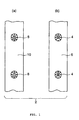
- FIG. 1 is a top view of a tape-mounted fastener 2 of one example of the present invention. It consists of a tape 6 (FIG. 1(b)) on which synthetic resin male parts 4 are attached and a tape 10 (FIG. 1(a)) on which synthetic resin female parts 8 are attached.
- FIG. 1(a) is drawn with the engagement surface up. This side is called the “face” side, and the surface opposite the "face” side is called the “back” side.
- FIG. 1b is drawn with the side opposite the engagement surface up. This side is called the “back” side, and the engagement surface side is called the "face” side.
- FIGS. 2 - 4 show the male part 4.
- FIG. 2 is a cross sectional view
- FIG. 3 is a back view
- FIG. 4 is a perspective view.
- the base 12 of the male part 4 is generally elliptical, and is firmly adhered to the cloth tape 6 provided with engagement sockets 14 by injection moulding. So that the tape 6 does not become twisted by the injection pressure during the injection moulding process, the upper and lower dies for moulding the peripheral part of the base 12 are provided with several pins (not shown) that press the tape 6. Because of this process, there are holes 16 on the base 12 that have a shape complementing the pin shape.
- the engagement protrusion 18 extends diagonally upwards in the direction of the engagement hole 14.
- the head 18a of this protrusion is parallel with the cloth tape 6, and on the protrusion-forming slanting surface 18b a small protrusion 18c having a triangular cross section is formed on the engagement hole side.
- the slant angle of the protrusion-forming slanting surface 18b is from 30 to 60 degrees, and preferably 45 degrees. There is no protrusion-forming slanting surface on the "back" side of the base 12, but there is a perpendicular surface 18d.
- a slanting surface 12a that is parallel with the protrusion-forming slanting surface 18b is formed.
- a perpendicular surface 12b and a curved surface 12c that spreads out from the perpendicular surface 12b are formed.
- Numeral 12d is an indentation that serves as a mark indicating the engagement direction. This indentation 12d is not an essential part of the present invention.
- FIGS. 5 - 7 show the female part.
- FIG. 5 is a cross sectional view
- FIG. 6 is a plan view
- FIG. 7 is a perspective view.
- the base 20 of the female part 8 is also generally elliptical, and is firmly adhered to the cloth tape 10 provided with engagement sockets 21 by injection moulding. So that the tape 10 does not become twisted by the injection pressure during the injection moulding process, the upper and lower dies for moulding the peripheral part of the base 20 are provided with several pins (not shown) that press the tape 10. Because of this process, there are holes 22 on the base 20 that have a shape complementing the pin shape.
- the engagement protrusion 23 extends diagonally upwards in the direction of the engagement hole 21.
- the head 23a of this protrusion is parallel with the cloth tape 10, and on the protrusion-forming slanting surface 23b a step 23c is formed on the engagement hole side.
- the slant angle of the protrusion-forming slanting surface 23b is from 30 to 60 degrees, and preferably 45 degrees. There is no protrusion-forming slanting surface on the "back" side of the base 20, but there is a perpendicular surface 23d.
- the engagement protrusion 23 of the female part 8 is different from the engagement protrusion 18 of the male part 4 in that it has a wall 23e on both of its sides, forming the engagement socket 21 as well as the space for housing the male part engagement protrusion when the male and female parts are engaged.
- a slanting surface 20a that is parallel with the protrusion-forming slanting surface 23b is formed.
- a perpendicular surface 20b and a curved surface 20c that spreads out from the perpendicular surface 20b are formed.
- Numeral 20d is an indentation that serves as a mark indicating the engagement direction. This indentation 20d is not an essential part of the present invention.
- FIG. 8 is a cross sectional view showing a process in which the male part 4 and the female part 8 are being engaged or disengaged.
- FIG. 9 is a cross sectional view of the male and female parts engaged.
- the male part 4 and the female part 8 engage or disengage in such a way that they slide on their respective protrusion-forming slanting surfaces. Therefore, the snap fastener of the present invention has a directionality not only for disengaging the male and female parts but also for engaging them.
- the small protrusion 18c of the male part 4 sits on the step 23c of the female part 8 to stabilize the engagement.
Landscapes
- Slide Fasteners, Snap Fasteners, And Hook Fasteners (AREA)
- Package Frames And Binding Bands (AREA)
- Purses, Travelling Bags, Baskets, Or Suitcases (AREA)
- Buckles (AREA)
- Toys (AREA)
- Push-Button Switches (AREA)
- Closing And Opening Devices For Wings, And Checks For Wings (AREA)
Claims (6)
- Auf einem Band befestigter Druckknopf mit einer Öffnungsund Schließrichtung, der ein männliches Band und ein weibliches Band umfasst, wobei das männliche Band aus einem Stoffband (6) hergestellt ist, auf dem mehrere männliche Teile (4) aus Kunststoff geformt und in gewissen Abständen befestigt sind, und das weibliche Band aus einem Stoffband (10) hergestellt ist, auf dem mehrere weibliche Teile (8) aus Kunststoff geformt und in gewissen Abständen befestigt sind,
dadurch gekennzeichnet, dass von der Vorderseite der Basis (12) des männlichen Teils (4) sich ein Eingriffsvorsprung (18) diagonal nach oben in Richtung einer Eingriffsfassung (14) erstreckt, wobei eine schräge Oberfläche (12a) parallel zu der den Vorsprung bildenden Fläche (18b) in der Eingriffsfassung (14) an der Vorderseite der Basis (12) geformt ist, und sich von der Vorderseite der Basis (20) des weiblichen Teils (8) ein Eingriffsvorsprung (23) diagonal nach unten in Richtung einer Eingriffsfassung (21) erstreckt, wobei eine schräge Fläche (20a) parallel zu der den Vorsprung bildenden schrägen Fläche (23b) in der Eingriffsfassung (21) an der Vorderseite der Basis (20) geformt ist, welche den Raum zur Aufnahme des Eingriffsvorsprungs (18) des männlichen Teils bildet, wenn die männlichen und weiblichen Teile ineinander eingreifen. - Druckknopf nach Anspruch 1, wobei die den Vorsprung bildende schräge Fläche (18b) auf der Eingriffsfassungsseite des männlichen Teils (4) mit einem kleinen Vorsprung (18c) versehen ist und die den Vorsprung bildende schräge Fläche (23b) auf der Eingriffsfassungsseite des weiblichen Teiles (8) mit einer Stufe (23c) versehen ist.
- Druckknopf nach Anspruch 2, wobei der kleine Vorsprung (18c) des männlichen Teiles (4) mit der Stufe (23c) des weiblichen Teils (8) zusammenwirkt, wenn die männlichen und weiblichen Teile vollständig ineinander eingreifen.
- Druckknopf nach einem der Ansprüche 1 bis 3, wobei der schräge Winkel der den Vorsprung bildenden schrägen Flächen (18b, 23b) 30° bis 60° beträgt.
- Druckknopf nach einem der Ansprüche 1 bis 4, wobei die Köpfe (18a, 23a) der Eingriffsvorsprünge (18, 23) der männlichen und weiblichen Teile (4, 8) vorzugsweise parallel zu ihren jeweiligen Stoffbändern verlaufen.
- Druckknopf nach Anspruch 1 bis 5, wobei wenigstens eines der männlichen und weiblichen Teile (4, 8) mit einer Markierung (12d, 20d) versehen ist, welche die Schließrichtung anzeigt.
Applications Claiming Priority (2)
| Application Number | Priority Date | Filing Date | Title |
|---|---|---|---|
| JP26136599 | 1999-09-16 | ||
| JP26136599A JP3566597B2 (ja) | 1999-09-16 | 1999-09-16 | 着脱の方向性を有するテープ付きスナップファスナ |
Publications (3)
| Publication Number | Publication Date |
|---|---|
| EP1084641A2 EP1084641A2 (de) | 2001-03-21 |
| EP1084641A3 EP1084641A3 (de) | 2001-12-12 |
| EP1084641B1 true EP1084641B1 (de) | 2004-03-17 |
Family
ID=17360837
Family Applications (1)
| Application Number | Title | Priority Date | Filing Date |
|---|---|---|---|
| EP00115600A Expired - Lifetime EP1084641B1 (de) | 1999-09-16 | 2000-07-19 | Druckknopf mit Öffnung und Schliessung in einer gewissen Richtung |
Country Status (10)
| Country | Link |
|---|---|
| US (1) | US6401308B1 (de) |
| EP (1) | EP1084641B1 (de) |
| JP (1) | JP3566597B2 (de) |
| KR (1) | KR100674787B1 (de) |
| CN (1) | CN1125609C (de) |
| AT (1) | ATE261674T1 (de) |
| AU (1) | AU764762B2 (de) |
| DE (1) | DE60008987T2 (de) |
| ES (1) | ES2216777T3 (de) |
| TW (1) | TW457856U (de) |
Families Citing this family (26)
| Publication number | Priority date | Publication date | Assignee | Title |
|---|---|---|---|---|
| JP3939965B2 (ja) * | 2001-11-19 | 2007-07-04 | グンゼ株式会社 | ブラジャー類の留め具、その製造方法及びそれを用いたブラジャー類 |
| JP4052949B2 (ja) * | 2003-01-09 | 2008-02-27 | モリト株式会社 | 引き剥がしの方向性を有するスナップファスナ |
| US8484813B2 (en) | 2009-02-23 | 2013-07-16 | Ykk Corporation | Snap button |
| JP6017882B2 (ja) * | 2011-08-29 | 2016-11-02 | モリト株式会社 | 合成樹脂製のかぎホック |
| US10932531B2 (en) | 2016-07-21 | 2021-03-02 | Florin Morar | Fastening device |
| US10292462B2 (en) * | 2016-07-21 | 2019-05-21 | Florin Morar | Fastening device |
| US11685573B2 (en) | 2017-06-12 | 2023-06-27 | Yeti Coolers, Llc | Carry strap for container |
| JP7101199B2 (ja) | 2017-06-12 | 2022-07-14 | イエティ クーラーズ エルエルシー | コンテナおよびラッチング・システム |
| US12108853B2 (en) | 2019-01-06 | 2024-10-08 | Yeti Coolers, Llc | Luggage system |
| US11976498B2 (en) | 2017-06-12 | 2024-05-07 | Yeti Coolers, Llc | Container and latching system |
| AU201717615S (en) | 2017-06-12 | 2018-01-15 | Yeti Coolers | Container |
| USD907445S1 (en) | 2018-12-11 | 2021-01-12 | Yeti Coolers, Llc | Container accessories |
| USD904829S1 (en) | 2018-12-11 | 2020-12-15 | Yeti Coolers, Llc | Container accessories |
| JP7303313B2 (ja) | 2019-01-06 | 2023-07-04 | イエティ クーラーズ エルエルシー | 荷物システム |
| US12225993B2 (en) | 2019-01-06 | 2025-02-18 | Yeti Coolers, Llc | Luggage system |
| USD951643S1 (en) | 2020-06-30 | 2022-05-17 | Yeti Coolers, Llc | Luggage |
| USD961926S1 (en) | 2020-06-30 | 2022-08-30 | Yeti Coolers, Llc | Luggage |
| USD954436S1 (en) | 2020-06-30 | 2022-06-14 | Yeti Coolers, Llc | Luggage |
| USD963344S1 (en) | 2020-06-30 | 2022-09-13 | Yeti Coolers, Llc | Luggage |
| DE102020132058A1 (de) * | 2020-12-02 | 2022-06-02 | Maschinenfabrik Rieter Ag | Elastische Putzlippe, Tragelement und Reinigungseinrichtung |
| USD994438S1 (en) | 2020-12-16 | 2023-08-08 | Yeti Coolers, Llc | Container |
| USD960648S1 (en) | 2020-12-16 | 2022-08-16 | Yeti Coolers, Llc | Container accessory |
| USD985937S1 (en) | 2020-12-16 | 2023-05-16 | Yeti Coolers, Llc | Container |
| KR102441497B1 (ko) * | 2021-04-07 | 2022-09-07 | (주)에이치제이씨 | 헬멧 |
| USD1061330S1 (en) | 2024-06-03 | 2025-02-11 | Dubrosky & Tracy Patent Service Corp. | Reversible garment closure part |
| US20260069000A1 (en) * | 2024-09-06 | 2026-03-12 | Dubrosky & Tracy Patent Service Corp. | Reversible garment closure |
Family Cites Families (16)
| Publication number | Priority date | Publication date | Assignee | Title |
|---|---|---|---|---|
| US569213A (en) * | 1896-10-13 | Friedrich max lehnig | ||
| US573829A (en) * | 1896-12-22 | Fastener or clasp for articles of apparel | ||
| US1337118A (en) * | 1919-01-31 | 1920-04-13 | Carr Fastener Co Ltd | Fastener |
| US1593452A (en) * | 1925-05-14 | 1926-07-20 | Hertzman Aaron | Adjustable cap |
| US1678166A (en) * | 1926-11-22 | 1928-07-24 | Fernando Spangenberg | Separable fastener |
| US2379896A (en) * | 1943-11-24 | 1945-07-10 | Jr Walter H Fitzgerald | Snap fastener |
| DE871732C (de) * | 1950-04-03 | 1953-03-26 | Gerber & Co | Druckknopf |
| US3350752A (en) * | 1966-08-02 | 1967-11-07 | Walter A Plummer | Laterally-engaging self-locking plastic seam assembly |
| US3545048A (en) * | 1968-12-16 | 1970-12-08 | Scovill Manufacturing Co | Snap fastener |
| US3751770A (en) * | 1971-07-26 | 1973-08-14 | L Italiano | Closures |
| FI69958C (fi) * | 1981-10-09 | 1986-09-12 | Salmi Reissverschluss Gmbh | Tillslutningsbandprodukt och foerfarande foer tillverkning av densamma |
| ES264444Y (es) * | 1982-04-07 | 1983-11-16 | Dispositivo de abroche. | |
| JPS6021458U (ja) * | 1983-07-20 | 1985-02-14 | 北川工業株式会社 | 消磁コイル保持具 |
| US4819309A (en) * | 1987-08-27 | 1989-04-11 | Minnesota Mining And Manufacturing Company | Fastener with parts having projecting engaging portions |
| JP3106199B2 (ja) * | 1996-07-29 | 2000-11-06 | モリト株式会社 | テープ付きスナップ |
| DE29908605U1 (de) * | 1999-05-14 | 2000-09-21 | Triumph International AG, 80335 München | Verschluß für Kleidungsstücke, insbesondere Miederwaren |
-
1999
- 1999-09-16 JP JP26136599A patent/JP3566597B2/ja not_active Expired - Fee Related
-
2000
- 2000-07-19 AT AT00115600T patent/ATE261674T1/de not_active IP Right Cessation
- 2000-07-19 ES ES00115600T patent/ES2216777T3/es not_active Expired - Lifetime
- 2000-07-19 DE DE60008987T patent/DE60008987T2/de not_active Expired - Lifetime
- 2000-07-19 EP EP00115600A patent/EP1084641B1/de not_active Expired - Lifetime
- 2000-07-24 AU AU48786/00A patent/AU764762B2/en not_active Ceased
- 2000-07-25 US US09/624,742 patent/US6401308B1/en not_active Expired - Fee Related
- 2000-08-08 TW TW089213715U patent/TW457856U/zh not_active IP Right Cessation
- 2000-08-16 CN CN00122695A patent/CN1125609C/zh not_active Expired - Fee Related
- 2000-08-29 KR KR1020000050336A patent/KR100674787B1/ko not_active Expired - Fee Related
Also Published As
| Publication number | Publication date |
|---|---|
| JP2001078809A (ja) | 2001-03-27 |
| HK1034171A1 (en) | 2001-10-19 |
| TW457856U (en) | 2001-10-01 |
| JP3566597B2 (ja) | 2004-09-15 |
| DE60008987T2 (de) | 2005-03-10 |
| ATE261674T1 (de) | 2004-04-15 |
| KR20010067126A (ko) | 2001-07-12 |
| EP1084641A2 (de) | 2001-03-21 |
| EP1084641A3 (de) | 2001-12-12 |
| CN1125609C (zh) | 2003-10-29 |
| US6401308B1 (en) | 2002-06-11 |
| CN1288700A (zh) | 2001-03-28 |
| KR100674787B1 (ko) | 2007-01-25 |
| AU4878600A (en) | 2001-03-22 |
| AU764762B2 (en) | 2003-08-28 |
| DE60008987D1 (de) | 2004-04-22 |
| ES2216777T3 (es) | 2004-11-01 |
Similar Documents
| Publication | Publication Date | Title |
|---|---|---|
| EP1084641B1 (de) | Druckknopf mit Öffnung und Schliessung in einer gewissen Richtung | |
| US5671508A (en) | Cord fastener | |
| JP3049381B2 (ja) | ツーピース・バックル | |
| EP1018609B1 (de) | Seilklemme | |
| US3844000A (en) | Clasp | |
| US6421887B1 (en) | Bottom end stop for slide fastener | |
| CA1319495C (en) | Strap fastener | |
| JP3733232B2 (ja) | テープ付雌雄形係止具 | |
| CN1198525C (zh) | 将扣件连接到片状物体上的附件结构 | |
| KR100399516B1 (ko) | 결합장치를 구비한 교합 슬라이드 파스너 | |
| EP0704177B1 (de) | Trennbarer unterer Endanschlag aus synthetischem Harz für Reissverschlüsse | |
| US7117567B1 (en) | Two-part connecting zipper pull | |
| US20020062539A1 (en) | Snap fastener | |
| CN205757617U (zh) | 绳带扣 | |
| US20060075612A1 (en) | Lower stop arrangement for concealed zipper | |
| JP2004049503A (ja) | スライドファスナー用スライダー | |
| EP0893076B1 (de) | Trennbarer unterer Endanschlag für Reissverschlüsse | |
| EP1090561A2 (de) | Taillenbandverstellvorrichtung | |
| US5187842A (en) | Slider pull tab for slide fastener | |
| EP1166662A2 (de) | Linearer Verschluss | |
| CA2005171C (en) | Buckle | |
| JP3532418B2 (ja) | 衣服用フック | |
| HK1034171B (en) | A tape-mouted snap fastener having an enagement and disengagement directionality | |
| JPS59103606A (ja) | ホツクの雌部用バネ部材 | |
| JPH0126249Y2 (de) |
Legal Events
| Date | Code | Title | Description |
|---|---|---|---|
| PUAI | Public reference made under article 153(3) epc to a published international application that has entered the european phase |
Free format text: ORIGINAL CODE: 0009012 |
|
| AK | Designated contracting states |
Kind code of ref document: A2 Designated state(s): AT BE CH CY DE DK ES FI FR GB GR IE IT LI LU MC NL PT SE |
|
| AX | Request for extension of the european patent |
Free format text: AL;LT;LV;MK;RO;SI |
|
| PUAL | Search report despatched |
Free format text: ORIGINAL CODE: 0009013 |
|
| AK | Designated contracting states |
Kind code of ref document: A3 Designated state(s): AT BE CH CY DE DK ES FI FR GB GR IE IT LI LU MC NL PT SE |
|
| AX | Request for extension of the european patent |
Free format text: AL;LT;LV;MK;RO;SI |
|
| 17P | Request for examination filed |
Effective date: 20020413 |
|
| AKX | Designation fees paid |
Free format text: AT BE CH CY DE DK ES FI FR GB GR IE IT LI LU MC NL PT SE |
|
| GRAP | Despatch of communication of intention to grant a patent |
Free format text: ORIGINAL CODE: EPIDOSNIGR1 |
|
| GRAS | Grant fee paid |
Free format text: ORIGINAL CODE: EPIDOSNIGR3 |
|
| GRAA | (expected) grant |
Free format text: ORIGINAL CODE: 0009210 |
|
| AK | Designated contracting states |
Kind code of ref document: B1 Designated state(s): AT BE CH CY DE DK ES FI FR GB GR IE IT LI LU MC NL PT SE |
|
| PG25 | Lapsed in a contracting state [announced via postgrant information from national office to epo] |
Ref country code: LI Free format text: LAPSE BECAUSE OF FAILURE TO SUBMIT A TRANSLATION OF THE DESCRIPTION OR TO PAY THE FEE WITHIN THE PRESCRIBED TIME-LIMIT Effective date: 20040317 Ref country code: AT Free format text: LAPSE BECAUSE OF FAILURE TO SUBMIT A TRANSLATION OF THE DESCRIPTION OR TO PAY THE FEE WITHIN THE PRESCRIBED TIME-LIMIT Effective date: 20040317 Ref country code: CY Free format text: LAPSE BECAUSE OF FAILURE TO SUBMIT A TRANSLATION OF THE DESCRIPTION OR TO PAY THE FEE WITHIN THE PRESCRIBED TIME-LIMIT Effective date: 20040317 Ref country code: FI Free format text: LAPSE BECAUSE OF FAILURE TO SUBMIT A TRANSLATION OF THE DESCRIPTION OR TO PAY THE FEE WITHIN THE PRESCRIBED TIME-LIMIT Effective date: 20040317 Ref country code: CH Free format text: LAPSE BECAUSE OF FAILURE TO SUBMIT A TRANSLATION OF THE DESCRIPTION OR TO PAY THE FEE WITHIN THE PRESCRIBED TIME-LIMIT Effective date: 20040317 Ref country code: BE Free format text: LAPSE BECAUSE OF FAILURE TO SUBMIT A TRANSLATION OF THE DESCRIPTION OR TO PAY THE FEE WITHIN THE PRESCRIBED TIME-LIMIT Effective date: 20040317 |
|
| REG | Reference to a national code |
Ref country code: GB Ref legal event code: FG4D |
|
| REG | Reference to a national code |
Ref country code: CH Ref legal event code: EP |
|
| REG | Reference to a national code |
Ref country code: IE Ref legal event code: FG4D |
|
| REF | Corresponds to: |
Ref document number: 60008987 Country of ref document: DE Date of ref document: 20040422 Kind code of ref document: P |
|
| PG25 | Lapsed in a contracting state [announced via postgrant information from national office to epo] |
Ref country code: GR Free format text: LAPSE BECAUSE OF FAILURE TO SUBMIT A TRANSLATION OF THE DESCRIPTION OR TO PAY THE FEE WITHIN THE PRESCRIBED TIME-LIMIT Effective date: 20040617 Ref country code: DK Free format text: LAPSE BECAUSE OF FAILURE TO SUBMIT A TRANSLATION OF THE DESCRIPTION OR TO PAY THE FEE WITHIN THE PRESCRIBED TIME-LIMIT Effective date: 20040617 |
|
| REG | Reference to a national code |
Ref country code: SE Ref legal event code: TRGR |
|
| PG25 | Lapsed in a contracting state [announced via postgrant information from national office to epo] |
Ref country code: LU Free format text: LAPSE BECAUSE OF NON-PAYMENT OF DUE FEES Effective date: 20040719 Ref country code: IE Free format text: LAPSE BECAUSE OF NON-PAYMENT OF DUE FEES Effective date: 20040719 |
|
| PG25 | Lapsed in a contracting state [announced via postgrant information from national office to epo] |
Ref country code: MC Free format text: LAPSE BECAUSE OF NON-PAYMENT OF DUE FEES Effective date: 20040731 |
|
| REG | Reference to a national code |
Ref country code: CH Ref legal event code: PL |
|
| REG | Reference to a national code |
Ref country code: ES Ref legal event code: FG2A Ref document number: 2216777 Country of ref document: ES Kind code of ref document: T3 |
|
| ET | Fr: translation filed | ||
| PLBE | No opposition filed within time limit |
Free format text: ORIGINAL CODE: 0009261 |
|
| STAA | Information on the status of an ep patent application or granted ep patent |
Free format text: STATUS: NO OPPOSITION FILED WITHIN TIME LIMIT |
|
| 26N | No opposition filed |
Effective date: 20041220 |
|
| REG | Reference to a national code |
Ref country code: IE Ref legal event code: MM4A |
|
| PG25 | Lapsed in a contracting state [announced via postgrant information from national office to epo] |
Ref country code: PT Free format text: LAPSE BECAUSE OF NON-PAYMENT OF DUE FEES Effective date: 20040817 |
|
| PG25 | Lapsed in a contracting state [announced via postgrant information from national office to epo] |
Ref country code: IT Free format text: LAPSE BECAUSE OF NON-PAYMENT OF DUE FEES Effective date: 20080719 |
|
| PGRI | Patent reinstated in contracting state [announced from national office to epo] |
Ref country code: IT Effective date: 20110101 |
|
| PGFP | Annual fee paid to national office [announced via postgrant information from national office to epo] |
Ref country code: ES Payment date: 20120716 Year of fee payment: 13 |
|
| PGFP | Annual fee paid to national office [announced via postgrant information from national office to epo] |
Ref country code: GB Payment date: 20130726 Year of fee payment: 14 Ref country code: FR Payment date: 20130730 Year of fee payment: 14 |
|
| PGFP | Annual fee paid to national office [announced via postgrant information from national office to epo] |
Ref country code: NL Payment date: 20140726 Year of fee payment: 15 |
|
| PGFP | Annual fee paid to national office [announced via postgrant information from national office to epo] |
Ref country code: SE Payment date: 20140721 Year of fee payment: 15 |
|
| PGFP | Annual fee paid to national office [announced via postgrant information from national office to epo] |
Ref country code: IT Payment date: 20140730 Year of fee payment: 15 |
|
| GBPC | Gb: european patent ceased through non-payment of renewal fee |
Effective date: 20140719 |
|
| REG | Reference to a national code |
Ref country code: FR Ref legal event code: ST Effective date: 20150331 |
|
| PG25 | Lapsed in a contracting state [announced via postgrant information from national office to epo] |
Ref country code: FR Free format text: LAPSE BECAUSE OF NON-PAYMENT OF DUE FEES Effective date: 20140731 Ref country code: GB Free format text: LAPSE BECAUSE OF NON-PAYMENT OF DUE FEES Effective date: 20140719 |
|
| REG | Reference to a national code |
Ref country code: ES Ref legal event code: FD2A Effective date: 20150828 |
|
| PG25 | Lapsed in a contracting state [announced via postgrant information from national office to epo] |
Ref country code: ES Free format text: LAPSE BECAUSE OF NON-PAYMENT OF DUE FEES Effective date: 20140720 |
|
| REG | Reference to a national code |
Ref country code: SE Ref legal event code: EUG |
|
| REG | Reference to a national code |
Ref country code: NL Ref legal event code: MM Effective date: 20150801 |
|
| PG25 | Lapsed in a contracting state [announced via postgrant information from national office to epo] |
Ref country code: IT Free format text: LAPSE BECAUSE OF NON-PAYMENT OF DUE FEES Effective date: 20150719 |
|
| PG25 | Lapsed in a contracting state [announced via postgrant information from national office to epo] |
Ref country code: NL Free format text: LAPSE BECAUSE OF NON-PAYMENT OF DUE FEES Effective date: 20150801 Ref country code: SE Free format text: LAPSE BECAUSE OF NON-PAYMENT OF DUE FEES Effective date: 20150720 |
|
| PGFP | Annual fee paid to national office [announced via postgrant information from national office to epo] |
Ref country code: DE Payment date: 20160719 Year of fee payment: 17 |
|
| REG | Reference to a national code |
Ref country code: DE Ref legal event code: R119 Ref document number: 60008987 Country of ref document: DE |
|
| PG25 | Lapsed in a contracting state [announced via postgrant information from national office to epo] |
Ref country code: DE Free format text: LAPSE BECAUSE OF NON-PAYMENT OF DUE FEES Effective date: 20180201 |