EP1083696B1 - Système et méthode de routage de paquets distribué en niveaux dans des anneaux à fibre optique - Google Patents
Système et méthode de routage de paquets distribué en niveaux dans des anneaux à fibre optique Download PDFInfo
- Publication number
- EP1083696B1 EP1083696B1 EP00119349A EP00119349A EP1083696B1 EP 1083696 B1 EP1083696 B1 EP 1083696B1 EP 00119349 A EP00119349 A EP 00119349A EP 00119349 A EP00119349 A EP 00119349A EP 1083696 B1 EP1083696 B1 EP 1083696B1
- Authority
- EP
- European Patent Office
- Prior art keywords
- fiber optic
- node
- forwarding
- network
- optic ring
- Prior art date
- Legal status (The legal status is an assumption and is not a legal conclusion. Google has not performed a legal analysis and makes no representation as to the accuracy of the status listed.)
- Expired - Lifetime
Links
Images


Classifications
-
- H—ELECTRICITY
- H04—ELECTRIC COMMUNICATION TECHNIQUE
- H04J—MULTIPLEX COMMUNICATION
- H04J14/00—Optical multiplex systems
- H04J14/02—Wavelength-division multiplex systems
- H04J14/0278—WDM optical network architectures
- H04J14/0283—WDM ring architectures
-
- H—ELECTRICITY
- H04—ELECTRIC COMMUNICATION TECHNIQUE
- H04J—MULTIPLEX COMMUNICATION
- H04J14/00—Optical multiplex systems
- H04J14/02—Wavelength-division multiplex systems
- H04J14/0227—Operation, administration, maintenance or provisioning [OAMP] of WDM networks, e.g. media access, routing or wavelength allocation
- H04J14/0228—Wavelength allocation for communications one-to-all, e.g. broadcasting wavelengths
-
- H—ELECTRICITY
- H04—ELECTRIC COMMUNICATION TECHNIQUE
- H04J—MULTIPLEX COMMUNICATION
- H04J14/00—Optical multiplex systems
- H04J14/02—Wavelength-division multiplex systems
- H04J14/0227—Operation, administration, maintenance or provisioning [OAMP] of WDM networks, e.g. media access, routing or wavelength allocation
- H04J14/0238—Wavelength allocation for communications one-to-many, e.g. multicasting wavelengths
-
- H—ELECTRICITY
- H04—ELECTRIC COMMUNICATION TECHNIQUE
- H04J—MULTIPLEX COMMUNICATION
- H04J14/00—Optical multiplex systems
- H04J14/02—Wavelength-division multiplex systems
- H04J14/0227—Operation, administration, maintenance or provisioning [OAMP] of WDM networks, e.g. media access, routing or wavelength allocation
- H04J14/0241—Wavelength allocation for communications one-to-one, e.g. unicasting wavelengths
-
- H—ELECTRICITY
- H04—ELECTRIC COMMUNICATION TECHNIQUE
- H04L—TRANSMISSION OF DIGITAL INFORMATION, e.g. TELEGRAPHIC COMMUNICATION
- H04L45/00—Routing or path finding of packets in data switching networks
-
- H—ELECTRICITY
- H04—ELECTRIC COMMUNICATION TECHNIQUE
- H04L—TRANSMISSION OF DIGITAL INFORMATION, e.g. TELEGRAPHIC COMMUNICATION
- H04L45/00—Routing or path finding of packets in data switching networks
- H04L45/22—Alternate routing
-
- H—ELECTRICITY
- H04—ELECTRIC COMMUNICATION TECHNIQUE
- H04L—TRANSMISSION OF DIGITAL INFORMATION, e.g. TELEGRAPHIC COMMUNICATION
- H04L45/00—Routing or path finding of packets in data switching networks
- H04L45/28—Routing or path finding of packets in data switching networks using route fault recovery
-
- H—ELECTRICITY
- H04—ELECTRIC COMMUNICATION TECHNIQUE
- H04Q—SELECTING
- H04Q11/00—Selecting arrangements for multiplex systems
- H04Q11/0001—Selecting arrangements for multiplex systems using optical switching
- H04Q11/0062—Network aspects
-
- H—ELECTRICITY
- H04—ELECTRIC COMMUNICATION TECHNIQUE
- H04J—MULTIPLEX COMMUNICATION
- H04J14/00—Optical multiplex systems
- H04J14/02—Wavelength-division multiplex systems
- H04J14/0287—Protection in WDM systems
- H04J14/0293—Optical channel protection
-
- H—ELECTRICITY
- H04—ELECTRIC COMMUNICATION TECHNIQUE
- H04Q—SELECTING
- H04Q11/00—Selecting arrangements for multiplex systems
- H04Q11/0001—Selecting arrangements for multiplex systems using optical switching
- H04Q11/0062—Network aspects
- H04Q11/0066—Provisions for optical burst or packet networks
-
- H—ELECTRICITY
- H04—ELECTRIC COMMUNICATION TECHNIQUE
- H04Q—SELECTING
- H04Q11/00—Selecting arrangements for multiplex systems
- H04Q11/0001—Selecting arrangements for multiplex systems using optical switching
- H04Q11/0062—Network aspects
- H04Q2011/0073—Provisions for forwarding or routing, e.g. lookup tables
-
- H—ELECTRICITY
- H04—ELECTRIC COMMUNICATION TECHNIQUE
- H04Q—SELECTING
- H04Q11/00—Selecting arrangements for multiplex systems
- H04Q11/0001—Selecting arrangements for multiplex systems using optical switching
- H04Q11/0062—Network aspects
- H04Q2011/0079—Operation or maintenance aspects
- H04Q2011/0081—Fault tolerance; Redundancy; Recovery; Reconfigurability
Definitions
- the present invention relates generally to data transmission in fiber optic ring networks, by way of example, the synchronous optical networks, (SONET networks) and Synchronous Digital Hierarchy networks (SDH networks) and more particularly, to the routing of IP data packets through the fiber optic ring networks including SONET and SDH networks.
- SONET networks synchronous optical networks
- SDH networks Synchronous Digital Hierarchy networks
- LAN local area network
- a digitized signal can be transported from a source through a LAN and through the internet, to a final destination.
- a backbone data transport infrastructure by way of example, through a fiber optic ring network.
- the internet is, in essence, a collection of many large and small computer networks that are coupled together over high speed backbone data links such as T-1, T-3, OC-1 and OC-3. Stated differently, the internet is a network of networks. As a result of the creation of the internet, worldwide access may be achieved. People and their equipment may now communicate from most any civilized point to another in a fast and relatively inexpensive medium.
- TCP transmission control protocol/internet protocol
- IP transmission control protocol/internet protocol
- TCP is a connection-oriented protocol that first establishes a connection between two computer systems that are to exchange data. TCP then breaks a given digital information signal into packets having a defined format. The packets are then attached to headers that are for containing control and address information.
- a TCP packet in addition to a destination address, typically contains a sequence number that is to be used by the destination in reconstructing a signal that is similar to the original digital information that was broken into packets at the originating end.
- TCP packets also typically include port IDs, checksum values and other types of control information as is known by those skilled in the art.
- IP protocol is used for routing purposes.
- the IP protocol includes the destination and originating addresses and default gateway identifiers.
- IP routers therefore, are operable to evaluate IP protocol information for routing an IP data packet and to evaluate TCP protocol information for error control and other similar purposes.
- protocols and standards are often defined. These protocols and standards are used to guide the design of the communication devices, and more specifically, to guide the design of the operating logic and software within the devices. While communication devices that are designed in view of these standards do not always follow the suggested models exactly, they are usually compatible with the protocol-defined interfaces (physical and logical). In order to appreciate the construction and operation of many devices, it is important to generally understand the concepts of some of the significant protocol standards and models.
- ISO/OSI provides a network framework or model that allows equipment from different vendors to communicate with each other.
- the OSI model organizes the communication process into seven different categories or layers and places these layers in a sequence based on their relation to the user. Layers 1 through 3 deal provide actual network access and control. Layers 4 through 7 relate to the point to point communications between the message source and destination.
- Layer 1 includes the physical layer meaning the actual hardware that transmits currents having a voltage representing a bit of information. Layer 1 also provides for the functional and procedural characteristics of the hardware to activate, maintain, and deactivate physical data links that transparently pass the bit stream for communication between data link entities.
- Layer 2 is the data link layer or the technology specific transfer layer that effectuates and controls the actual transmissions between network entities. For example, layer 2 provides for activation, maintenance, and deactivation of data link connections, character and frame synchronization, grouping of bits into characters and frames, error control, media access control and flow control.
- Layer 3 is the network layer at which routing, switching and delaying decisions are made to create a path through a network. Such decisions are made in view of the network as a whole and of the available communication paths through the network. For example, decisions as to which nodes should be used to create a signal path are decided at layer 3. As may be seen, layers 1, 2 and 3 control the physical aspects of data transmission.
- layer 4 is the transport layer that defines the rules for information exchange and manages the point to point delivery of information within and between networks including providing error recovery and flow control.
- Layer 5 is the session layer that controls the basic communications that occur at layer 4.
- Layer 6 is the presentation layer that serves as a gateway (a type of "software" interface) between protocols and syntax of dissimilar systems.
- Layer 7 is the application layer that includes higher level functions for particular application services. Examples of layer 7 functions include file transfer, creation of virtual terminals, and remote file access.
- IP is a layer three protocol.
- many of the backbone data transport infrastructures utilize a different layer protocol than an internet router.
- Double ring TDM systems are generally known, especially for fiber-optic communication networks.
- TDM time division multiplexed
- Double ring TDM systems are generally known, especially for fiber-optic communication networks.
- the protection path is, traditionally, a redundant path for transmitting signals in a failure condition.
- fiber optic TDM systems include the SONET and SDH double ring fiber optic communication systems used in North America and Europe, respectively.
- either the user traffic (data) in the redundant path in these double ring systems is not routed through the protection path or, alternatively, it is routed but is not processed by a destination.
- its communication channels are reserved as an alternate path during failure conditions.
- the redundant path is typically used to route the data signals in an opposite direction from the working path so that data that is to be routed to a destination node located, "downstream" from the failure condition may still be delivered to the destination node.
- layer 1 overhead signaling messages are generated and transmitted back to the ingress node (among other nodes) identifying the fault condition so that the protection switching may occur quickly. More specifically, layer 1 overhead signaling messages are transmitted by the nodes detecting the error (typically the two nodes on either traffic side of the detected problem) on a communication link so that the ingress node may effectuate the change on a quick basis.
- the ingress node includes dedicated circuitry for reading, interpreting and quickly responding to the overhead signaling message to effectuate a change.
- the overhead signaling is set upon the occurrence of a significant hardware failure in a communication link.
- EP 0 909 062 A1 discloses a method and apparatus for accelerating a router in a communications network.
- a router accelerator includes a forwarding table for associatively storing a destination address and a next hop address. If a destination address of a packet matches a destination address in the forwarding table, then logic forwards the packet to a next hop.
- the present invention contemplates a fiber optic ring network that includes a plurality of fiber optic ring networks that provide routing of IP traffic.
- User traffic may be conducted on a working path or on a protection path in the event of a communication link failure in the working path.
- a central node is coupled to a plurality of nodes to provide a forwarding table for the nodes to use to forward a data packet received from the central node.
- the central node also provides updates for the forwarding table to the nodes.
- IP traffic may be routed through the fiber optic ring network in a manner that provides fast switching from a working path to a protection path to minimize lost data packets whenever a communication link in the working path fails. Additionally, this capability is provided without requiring each node to have full IP routing capability. Because the central node creates and provides forwarding tables and forwarding table updates for each of the nodes on the fiber optic ring network, the individual nodes are not required.
- the forwarding table provides path routes and forwarding for the data packets on a packet by packet basis. Accordingly, large amounts communication resources need not be reserved for protection purposes because the invention provides of protection path switching for only those data packets whose working path route is affected by the communication link failure.
- the disclosed invention also provides an apparatus and a method for creating forwarding tables on a packet by packet basis for at least one virtual private network wherein a subscriber is assigned specified communication channels or resources for transporting the subscriber data. Additionally, a method and an apparatus are provided for forwarding data packets through the fiber optic ring network in a multicast transmission scheme wherein a given node receives a data packet, outputs it to an external destination, and also forwards the packet to another node in the fiber optic ring network. For this embodiment, the central node generates at least two forwarding tables for each node in the fiber optic ring network.
- Modern networks are being designed to transport user traffic containing varying types of information including voice, image, text, control signals and numerical data.
- the user traffic is routed through access multiplexers, gateways (interface devices for systems communicating using differing formats), add drop multiplexers (ADMs), fiber optic cross connects, ATM switches and internet protocol (IP) routers.
- ADMs add drop multiplexers
- IP internet protocol
- Fiber optic ring networks typically utilize a protocol that includes data packets having a fixed or defined length.
- SONET network "cell” is a data packet that allocates 48 bytes for data and 5 bytes for a header.
- the fiber optic ring network is, today, a dual ring fiber optic network that transports optical signals in a working path and, at least occasionally, in a protection path using time division multiplexing. Because fiber optic ring networks will increasingly be used to transport IP user data as the importance of the internet continues to grow, the fiber optic ring networks and IP networks must be made to coexist in a compatible and acceptable manner. By some estimates, IP traffic will be the most common type of traffic transported over fiber optic ring networks in the next century.
- FIG. 1 is a functional block diagram of a schematic of a network for transporting IP user traffic over a fiber optic ring.
- central IP router 100 is connected to deliver and receive IP user traffic to and from ADM 104.
- ADM 104 is coupled to transmit and receive user traffic over fiber optic ring 108 in a TDM format.
- Central IP router 100 is coupled to IP routers 112, 116 and 120 via control lines 114, 118 and 122, respectively, in a star configuration to control the routing of the user traffic for which central IP router 100 was the ingress node.
- each of the routers 100, 112, 116 and 120 are similar in structure.
- IP router 100 is a "central" IP router for all user traffic for which IP router 100 was the ingress point for the fiber optic ring network.
- central IP router 100 also is connected to the internet to receive internet user traffic as well as internet parameter data 124 as shown in Figure 1 .
- Internet parameter data includes information regarding networks and computer systems that are coupled to the internet as well as path information (e.g., communication link failures).
- Central IP router 100 uses the internet parameter information to determine IP packet routing whenever it receives a packet of data that is to be transmitted to a specified location.
- central IP router 100 receives user traffic in IP packet form from, by way of example, the internet and determines where the packet should be routed. For those packets that it determines should be routed through the fiber optic ring network, central IP router 100 produces the user traffic to the fiber optic ring ADM without any knowledge of the fiber optic ring architecture or its available paths. Central IP router 100 merely specifies the destination IP router address and allows ADM 104 to route the IP packets to the ADM that is coupled to the specified IP router that is specified in the IP path routes. Stated differently, central IP router 100 treats the ADM and the fiber optic ring merely as a transport layer.
- the IP router does not receive or evaluate information regarding topology (including layer 1 or layer 2 failure information) or restoration capability, for the fiber optic ring.
- the layer 3 routing functionality of central IP router 100 does not include any analysis of layer 1 and layer 2 operations in the fiber optic ring.
- the layer 3 functionality of central IP router 100 only detects a layer 1 failure condition in the fiber optic ring whenever user traffic fails to reach a destination.
- One advantage of the configuration of Figure 1 is that it provides for fast switching times in the fiber optic ring in the event of a layer 1 or layer 2 failure within the ring.
- a disadvantage is cost because it requires a full IP router and an ADM at each node of the fiber optic ring in addition to a separate star or mesh network coupling each IP router in the network to the central IP router 100.
- the fiber optic ring performs switching within its network in response to a failure transparently with respect to the IP router suggests that throughput redundancy is required.
- the capacity of the working paths in a fiber optic ring network must be duplicated in a protection path to have a system that transparently switches user traffic paths whenever a communication link failure occurs. It is common, by way of example, to have channels of at least 155 Mbps capacity to be fully reserved on the protection path for corresponding channels on the working path.
- FIG. 1 is advantageous in that protection switching occurs quickly at the layer 1 and layer 2 levels, it is not an economic solution in terms of transport efficiency.
- FIG 2 is a schematic diagram of a plurality of IP routers connected in a fiber optic ring for transporting IP user traffic over a fiber optic ring network.
- a central IP router 204 is coupled to IP routers 208, 212 and 216 via fiber optic ring 220.
- IP router 204 also is coupled to receiver user traffic and internet parameter data 124 from an external source (e.g., the internet).
- central IP router 204 receives user traffic and routes it through the fiber ring network of IP routers according to IP addresses specified in the headers of the IP packets according to TCP/IP formats and protocols.
- One advantage of the network of Figure 2 is that it is less expensive than the network of Figure 1 because it does not require the ADMs to route the IP user traffic yet it is capable of routing IP user traffic over a fiber optic ring network.
- communication link failures are detected at layer 3 when the IP router transmitting an IP packet of user traffic does not receive an expected signal. It would be advantageous to have a system in which functionality of layers 1 through 3 are provided in a system capable of responding to failures and conditions detected at any layer within fifty milliseconds.
- FIG. 3 is a functional block diagram of a fiber optic ring network according to a preferred embodiment of the invention.
- a central fiber optic ring network node 300 includes a memory 304 for storing a routing table for specifying routing through a fiber optic ring network (and beyond). Additionally, node 300 includes a memory 308 for storing a forwarding table for specifying packet forwarding through the fiber optic ring network.
- the network shown in Figure 3 also includes nodes 312, 316 and 320. Each of the nodes 300, 312, 316 and 320 are coupled in a ring topology by fiber optic ring 108 and by fiber optic ring 110.
- Rings 108 and 110 conduct traffic in circularly opposite directions to provide working and protection path routing to every node on the fiber optic ring network.
- the nodes are coupled by only one fiber optic ring 108.
- traffic is conducted in circularly opposite directions on the one ring 108.
- both embodiments are included even though only one of these two embodiments will be described in some instances.
- Control communications lines 324, 328 and 332 each couple nodes 312, 316 and 320 to central fiber optic ring network node 300 in a star topology.
- Node 300 transmits forwarding tables and table updates to nodes 312, 316 and 320 (the "forwarding nodes") over the control communication lines 324, 328 and 332.
- each of the nodes Upon receiving a table, each of the nodes stores it within memory 340
- Node 300 also transmits forwarding table updates to each of the forwarding nodes over control communication lines 324, 328 and 332.
- Figure 3 shows an update signal 336 being transmitted by node 300 to node 320 over control communication line 332.
- Each of the forwarding nodes updates the forwarding tables in memory 340 upon receiving update signal 336.
- node 300 determines the routing and generates forwarding tables to each of the forwarding nodes, cost and complexity is significantly reduced. One reason is that the forwarding nodes do not include the hardware or software required to be fully functioning IP routers.
- the forwarding tables that are produced to the forwarding nodes by node 300 include working path and protection path forwarding specifications.
- a multiprotocol label switching (MPLS) scheme is used to specify the forwarding.
- MPLS scheme logical path definitions are used to direct data packets in the fiber optic ring network.
- the forwarding tables merely specifies output ports and channel assignments on the ports for packets received from specified input ports on specified channels.
- the forwarding tables merely specify the destination node ID for the next communication link or a port if the packet is to be output from the fiber optic ring network. Accordingly, the forwarding tables may be set up in a plurality of different manners to achieve the same result.
- the central node determines the forwarding for the other nodes in the network. Accordingly, the other nodes do not require the complexity to be able to function as full IP routers.
- central node 300 whenever the central node 300 becomes aware from an overhead signaling message that a communication link has experienced a specified problem, by way of example, either congestion or a communication link outage, central node 300 assigns labels to the data packets it produces on the fiber optic ring network to cause some of the data packets to be transmitted on the protection path. Not all of the packets are then routed on the protection path. Only those data packets whose path route is affected by the communication link failure are routed on the protection path. In general, it is the data packets whose final destination on the fiber optic ring network is downstream (on the working path) that are assigned labels to cause them to be routed through the protection path.
- each of the forwarding tables includes forwarding information for the working paths as well as the protection paths.
- additional information may need to be provided to the nodes to enable them to determine whether to forward a packet along a working path or a protection path.
- FIG 4 is a functional schematic illustrating the components of a central ingress node according to a preferred embodiment of the invention.
- an ingress node 400 is a node that receives IP traffic that requires routing through the fiber optic ring network.
- the ingress node 400 is responsible for determining the path route for a data packet through the fiber optic ring network.
- Central ingress node 400 includes a processor 402 that is communicatively coupled to a memory 404, a storage device 406 and a peripheral bus interface through a bus 410.
- Peripheral bus interface is communicatively coupled with network interface devices 412A, 412B, 412C, 412D and 412E.
- Each of these network interface devices are connected, for exemplary purposes, to an IP router, an IP node, a first ring of a fiber optic ring network, a second ring of a fiber optic ring network, and a communication control line, respectively.
- Storage device 406 can be formed of any one or of a plurality of devices for storing operational logic, protocol information, programming steps and instructions, and gateway logic to convert signals from one protocol to another.
- portions 406A and 406B are for storing instructions for creating routing and forwarding tables.
- Portion 406C is for storing computer instructions that specify operational logic and communication protocols.
- portion 406C includes protocol information for serving as a gateway or interface device between the internet and the fiber optic ring network.
- portion 406C includes instructions that specify how and when tables and table updates are to be transmitted over the communication control lines 324, 328 and 332 of Figure 3 (for example).
- portion 406C includes at least two IDs. A first ID is an IP router ID while the second ID is an IP node ID.
- storage device 406 comprises, in the described embodiment, an electromagnetic disk drive that has read/write capability.
- storage device 406 comprises read only memory (ROM) circuits, compact disk (CD) ROM devices, Read/Write CDs, tape drives, floppy disks (and similar devices), and other known information storage mediums.
- forwarding tables that are created by processor 402 while executing the corresponding instructions stored within storage 406, different types of forwarding tables may be created according to designer preference.
- a label switching scheme may be used.
- a table may be created that merely utilizes IP identification numbers for specifying how a forwarding node is to forward a packet.
- IP router ID While an entire fiber optic ring network may have only on IP router ID so as to appear as only on IP router to other internet devices, each node may have a separate IP node ID.
- Memory 404 comprises random access memory (RAM) with read/write capability for storing operational information while node 400 is operational and is receiving power.
- RAM random access memory
- memory portions 404A and 404B are for storing the routing and forwarding tables, respectively, created by processor 402 while executing the programming instructions stored in memory portion 406A of storage device 406.
- Memory portion 406C is for storing information relating to network conditions. By way of example, if node 400 either determines on its own or is informed of a network communication link failure, information defining the type of failure and its location are stored in memory portion 406C of memory 406.
- memory 404 includes data used by processor 402 while executing program steps or computer instructions defined in portions 406A, 406B and 406C of storage device 406 as well as in other portions of the storage device.
- Memory 404 also is for, among other things, storing a fiber optic ring failure condition that was determined by node 300 or that was indicated in a received overhead signal. In terms of hardware characteristics of memory 404, different types of memory may be used. By way of example, memory 404 can comprise 32 bit flash program storage, dynamic RAM, static RAM, etc.
- Processor 402 is a standard processing unit formed within similar computerized devices and is capable of controlling operations of the node 400 according to the operational logic defined within storage 406.
- Processors that may be used include customized ASIC devices, off the shelf processors including common commercially available microprocessors and other similar devices.
- Peripheral bus interface 408 is a standard bus interface that allows processor 402 to communicate with and control the communications that occur over a plurality of network interface devices 412 that are coupled to peripheral bus interface 408.
- Network interface devices 412 are transceivers of various types that are coupled to communicate with specific devices. While the described embodiment includes a peripheral bus interface 408, other known devices may be substituted according to system implementation. By way of example, a cross connect switch is used in an alternate embodiment of the invention. In yet another embodiment, a demultiplexer is used in place of peripheral bus interface 408.
- the network interface devices of Figure 4 may be formed of different known interface systems. For example, they may comprise radio modems, digital signal processors, ASICs, T1/E1 interface devices, etc.
- the type of device utilized as a network interface device 412 is a function of the type of device with which it will be expected to communicate and can include transceivers of all known types.
- processor 402 of node 400 in the described embodiment, is operable, in conjunction with computer instructions in storage device 406, to detect and respond to the a communication link failure or traffic condition (e.g., congestion). Within the 15 milliseconds, processor 402 generates the overhead signal indicating a communication link failure or traffic condition within fifteen milliseconds of the communication link failure or condition being detected (collectively "communication link failure").
- a communication link failure or traffic condition e.g., congestion
- processor 402 Within the 15 milliseconds, processor 402 generates the overhead signal indicating a communication link failure or traffic condition within fifteen milliseconds of the communication link failure or condition being detected (collectively "communication link failure").
- processor 402 is operable, in conjunction with computer instructions in storage device 406, to detect and respond within a 35 millisecond period to a received overhead signal used to indicate a failure condition in a communication link within the fiber optic ring network. Stated differently, the programming instructions within storage device 406 are written to cause processor 402 to initiate protection path routing/forwarding within 35 milliseconds of receiving the overhead signal.
- processor firmware may be used to generate a flag or interrupt to cause the processor to execute a specified routine to initiate protection path forwarding/switching.
- processor 402 first calculates routing tables that are stored in a memory portion 404A of node 400 as described below.
- the forwarding tables for each of the nodes are then created so that the other nodes will forward user traffic at the packet level through the fiber optic ring network along path routes that are consistent with those defined in the routing tables created by logic device 324.
- the forwarding tables are created for the nodes on the fiber optic ring network in a network that utilize an MPLS scheme specify a one to one mapping between logical channels.
- Each logical channel has a unique channel Id known as a label. Accordingly, a central node is able to control the working path and protection path forwarding by selecting the mapping of labels in the forwarding tables for each of the nodes.
- typical fiber optic ring network defines a large number of channels that are transmitted through a ring. Accordingly, the forwarding tables define paths through the fiber optic ring channels.
- a channel having a label as an identifier is characterized by the ring on which it is carried, the carrier frequency and the time period at which the data packets are transmitted.
- a data packet in an embodiment utilizing an MPLS scheme therefore, is assigned a label that implicitly represents an output port, a carrier frequency and a time slot.
- FIG. 5 is a functional schematic illustrating the components of a node for forwarding data packets in a fiber optic ring network according to a preferred embodiment of the invention.
- a node 500 for the purposes herein, is a node that receives IP traffic that requires routing to an external node or forwarding through the fiber optic ring network.
- Node 500 includes a processor 502 that is communicatively coupled to a memory 504, a storage device 506 and a peripheral bus interface through a bus 510.
- Peripheral bus interface is communicatively coupled with network interface devices 512A, 512B, 512C, 512D and 512E.
- Each of these network interface devices are connected, for exemplary purposes, to an IP router, an IP node, a first ring of a fiber optic ring network, a second ring of a fiber optic ring network, and a communication control line, respectively.
- Storage device 506 can be formed of any one or of a plurality of devices for storing operational logic, protocol information, programming steps and instructions, and gateway logic to convert signals from one protocol to another.
- portion 506A is for storing computer instructions that define ring topology information including the ID numbers of each node and, in some embodiments, specific port IDs for the nodes of the fiber optic ring network.
- portion 506B is for storing computer instructions for forwarding data packets according to the contents of a forwarding table stored in memory.
- Portion 506C is for storing computer instructions that specify operational logic and communication protocols.
- portion 506C includes protocol information for serving as a gateway or interface device between the internet and the fiber optic ring network.
- portion 506C includes instructions that specify how data packets are to be transmitted. For example, if an MPLS scheme is used, how label swapping is to be performed. If another approach is used in a given configuration, portion 506C includes corresponding instructions to define logic for forwarding the packet. Finally, portion 506C includes at least two IDs. A first ID is an IP router ID while the second ID is an IP node ID.
- storage device 506 comprises, in the described embodiment, an electromagnetic disk drive that has read/write capability.
- storage device 506 comprises read only memory (ROM) circuits, compact disk (CD) ROM devices, Read/Write CDs, tape drives, floppy disks (and similar devices), and other known information storage mediums.
- Memory 504 comprises random access memory (RAM) with read/write capability for storing operational information while node 500 is operational and is receiving power.
- RAM random access memory
- memory portion 504A is for storing the forwarding table received from the central node over the communication control line.
- Portion 504B is for storing a received packet of user traffic while the node 500 determines how to forward the packet and, in some embodiments, for storing the packet while it is manipulated to be transmitted either onto the fiber optic ring network or externally to an IP node.
- memory 504 can comprise 32 bit flash program storage, dynamic RAM, static RAM, etc.
- Processor 502 is a standard processing unit formed within similar computerized devices and is capable of controlling operations of the node 500 according to the operational logic defined within storage 506. Customized ASIC devices, as well as off the shelf and common commercially available microprocessors and other similar devices may be used for processor 502.
- Peripheral bus interface 508 is a standard bus interface that allows processor 502 to communicate with and control the communications that occur over a plurality of network interface devices 512 that are coupled to peripheral bus interface 508.
- Network interface devices 512 are transceivers of various types that are coupled to communicate with specific devices. While the described embodiment includes a peripheral bus interface 508, other known devices may be substituted according to system implementation. By way of example, a cross connect switch and a demultiplexer are used in alternate embodiments of the invention instead of peripheral bus interface 508.
- the network interface devices of Figure 5 may be formed of different known interface systems. For example, they may comprise radio modems, digital signal processors, ASICs, T1/E1 interface devices, etc.
- the type of device utilized as a network interface device 512 is a function of the type of device with which it will be expected to communicate and can include transceivers of all known types.
- processor 502 of node 500 is operable, in conjunction with computer instructions in storage device 506, to receive a forwarding table transmitted by a central node 400, by way of example, and to store the forwarding table I memory portion 504A of memory 504.
- a central node 400 transmits the forwarding table over a control and communication line that is coupled to user interface device 512E.
- peripheral bus interface 508 communicates with user interface device and 512E and processor 502 to store the forwarding table in memory 504.
- processor 502 receives updates to the forwarding table and operates to modify the contents of memory 504A according to computer instructions in storage 506B.
- processor 502 outputs data packets through, by way of example, network interface 512C onto the first fiber optic ring at a specified frequency and at a specified time slot according to information stored in the forwarding table within memory portion 504A.
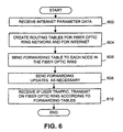
- FIG. 6 is a flow chart illustrating a method performed in a central fiber optic ring network node for routing data packets in a fiber optic ring network according to preferred embodiment of the invention.
- the node receives a signal 124 of Figure 1 that includes internet parameter data (step 602).
- every IP router periodically generates network status requests that are transmitted to all IP routers and nodes that are electrically present and coupled to the internet.
- every IP router and node periodically and automatically generates a status signal that is transmitted to all other IP nodes and routers.
- a node such as node 300 of Figure 3 periodically receives signals transmitted by nodes and routers coupled to the internet. It is through these signals that central node 300 may determine and construct routing tables that are used for directing user traffic to specific internet locations.
- central node 300 uses the internet parameter data to create routing tables for routing IP user traffic and to create forwarding tables for user traffic that is to be transported over the fiber optic ring network (step 604). As a part of creating these routing tables, central node 300 also examines the fiber optic ring network conditions. The ring conditions, by way of example, communication link failures, are used to create the routing tables.
- Central node 300 then generates and transmits a forwarding table to each node on the fiber optic ring network for the IP user traffic (step 606).
- the tables are transmitted to the nodes through a control communication line that couples each node to the central node 300.
- the tables are produced to the nodes through the fiber optic ring network.
- the forwarding tables define the channels for conducting user traffic for the working and protection paths for user traffic being originated. For example, each packet will have a direction working path or protection path), a frequency and a time slot specified for each communication link in the fiber optic ring network through which it is to be transported.
- the forwarding tables create a one to one label mapping. Accordingly, a received data packet will have a label that has a corresponding label in the forwarding table. The corresponding label identifies the channel on which the data packet is to be transmitted. Thus, the label defines the ring (assuming a two ring system), the frequency and the time slot in which the data packet is to be transmitted.
- the forwarding tables are, in the described embodiment, extracted from the routing tables.
- node 300 After the central node has transmitted working path and protection path forwarding tables to all of the nodes, it must maintain the information within the tables to keep it current. Accordingly, every time central node receives a signal 336 that defines new internet nodes or network conditions that require changes to the routing paths defined in the routing/forwarding tables, node 300 updates its tables and sends updates to the nodes on the fiber optic ring network (step 608).
- Node 300 also updates the working and protection paths for any data packets that require transport through a failed communication link within the fiber optic ring network to reach an internet address. Accordingly, depending upon the type of failure condition, a new working path and protection path may be established to reach a specified node for which the routing is affected by the communication link failure in the fiber optic ring network.
- the fiber optic ring network After the forwarding table updates (if necessary) and tables have been sent to the nodes on the fiber optic ring network, the fiber optic ring network is ready to transport user traffic. Accordingly, when central node 300 receives IP user traffic, it converts the IP user traffic to TDM format and transmits it onto the fiber optic ring network (step 610). The nodes on the fiber optic ring network then forward the converted IP user traffic as specified in their forwarding tables.
- FIG. 7 is a flow chart that illustrates a method in a fiber optic ring network node for forwarding a data packet according to a preferred embodiment of the invention.
- a node receives a forwarding table from a central fiber optic ring network node 300 (step 702).
- the node then stores the forwarding table.
- the node may receive updates for the tables from the central node (step 704).
- the updates will typically only be received, however, if there is a condition on the internet or on the fiber optic ring network that requires routing changes to be made to the forwarding tables. These update signals are used to update the stored forwarding tables.
- the node may also occasionally receive fiber optic ring status signals (step 706). For example, a signal may be received indicating that a communication link in the fiber optic ring has failed or is congested.
- the node stores the information as a part of maintaining ring status information.
- the node also receives data packets of user traffic that are to be forwarded through the fiber optic ring network (step 708). Whenever such a data packet is received, the node examines the contents of the forwarding table in relation to specific information within or known about the received user traffic. For one example, if an MPLS scheme is being used, the label within the header of the received data packet contains a corresponding label within the forwarding table. In such a case, the node examines the forwarding table to find the corresponding replacement label, and then inserts the replacement label in the header of the data packet. Thereafter, the node forwards the data packet according to the new label (step 710).
- the node examines specified destination information (e.g., destination node ID) within the header to determine whether the packet of user traffic is to be output or forwarded.
- the forwarding table includes, for this embodiment, either an indication of a specified port of the node through which the packet is to be output to the internet or an indication of the channel through which the packet of user traffic is to be transmitted.
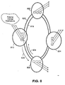
- FIG. 8 is a functional block diagram of a fiber optic ring network having a plurality of nodes, each having a plurality of forwarding tables to create virtual private networks according to a preferred embodiment of the invention.
- a fiber optic ring network includes a central ingress node 800 that is communicatively coupled to nodes 804, 808 and 812 by way of fiber optic ring 816 and fiber optic ring 820.
- ring 816 conducts user traffic in the direction shown at 824.
- Ring 820 conducts user traffic in the direction shown at 828.
- the embodiment shown in Figure 8 comprises two rings, namely rings 816 and 820
- alternate embodiments include a one ring system that is operable to conduct user traffic in two directions, namely, in the directions shown at 824 and 828.
- each node includes a plurality of memories within the node.
- Each of the memories represents an embodiment in which a plurality of so called virtual private networks are formed.
- a subscriber is allocated a path and supporting resources for the subscriber's exclusive use. Accordingly, in such an embodiment, a unique forwarding table is created for the subscriber that defines the data packet forwarding for that particular subscriber.
- a node having three tables illustrates the presence of at least two virtual private networks. The third forwarding table, therefore, is either for all other user traffic or, perhaps, merely for a third subscriber of a virtual private network.
- each forwarding table specifies whether the user traffic data packet is to be forwarded through the fiber optic ring network, whether it is to be output to an external internet destination, by way of example, to an external IP node, or whether it is to be output and forwarded (in a multicast transmission).
- a data packet is received and converted for outputting to a device as well as forwarded on through the net work.
- a multicast scheme is a scheme for broadcasting a message to a plurality of nodes.
- a data packet may be transmitted having a specified signal within the header to inform the node that it is a multicast signal.
- either a specified bit may be used to reflect that a signal is a multicast signal, or, within the forwarding table, a unique entry may exists to cause both outcomes to occur.
- the node if the header carries a unique destination ID that reflects that the signal is a multicast signal, the node is able to determine that the signal is to be output as well as forwarded. In this case, the node examines the forwarding table to know what output ports and forwarding paths are to be used. Thus, by way of example, if node 812 receives a multicast packet on line 824, it will not only output the signal to
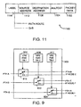
- FIG. 9 is a functional schematic diagram of a node having a plurality of forwarding tables, each corresponding to a virtual private network according to a preferred embodiment of the invention.
- a node 900 includes a plurality of memory portions for storing a plurality forwarding tables, one for each virtual private network (VPN). More specifically, memory portion 904 stores a first VPN forwarding table. Memory portion 908 stores a second VPN forwarding table. Memory portion 912 stores a third VPN forwarding table.
- VPN virtual private network
- Figure 9 also includes a plurality of logical switches 916, 920 and 924.
- Each of the switches 916, 920 and 924 include an input to receive data packets for specified paths on the fiber optic ring network.
- Each of the switches also includes a pair of outputs. One output is coupled to a specified IP node external to the fiber optic ring network. The other output is coupled to a specified path on the fiber optic ring network.
- each of the memories 904, 908 and 912 are coupled to a selector input of each of the logical switches 916, 920 and 924, respectively.
- Figure 9 is functional in nature. It should be understood that the actual schematic of node 900 resembles the circuitry shown for the node of Figure 5 .
- One purpose of Figure 9 is illustrate how the forwarding tables in a memory of a node having VPNs relate to the routing and forwarding of packets through a node.
- a processor similar to the one of Figure 5 , examines computer instructions within a storage device to determine a corresponding memory portion holding a corresponding forwarding table for a specified VPN according to the identity of the path from which a data packet was received.
- the processor 502 examines the corresponding forwarding table to determine whether the packet is to be output to a device on the internet having a IP node ID or whether it is to be forwarded on a specified path of the VPN to another node on the fiber optic ring network.
- Figure 10 is a flow chart illustrating a method for routing a data packet through a fiber optic ring network having a plurality of nodes, each having a plurality of forwarding tables to create virtual private networks according to a preferred embodiment of the invention.
- a node initially receives at least one forwarding table.
- the node receives a plurality of forwarding tables, one for each VPN (step 1002).
- the node optionally, receives updates to the forwarding tables to reflect routing and forwarding changes according either to internet or fiber optic ring topology changes resulting from failures and from actual changes to the configuration of the networks (step 1004).
- a node Once a node is set up with forwarding tables, it is ready and begins to receive user traffic in packet form (step 1006). On a packet by packets basis, the node must determine from examining a forwarding table how to forward or route the packet. If the fiber optic ring network includes VPNs, the node determines the appropriate forwarding table according to the path ID from which the packet was received (step 1008).
- the node In addition to determining the appropriate and corresponding forwarding table, the node also examines the header to determine if it includes an egress port address that is a port of the node (step 1010). In alternate embodiments, the node determines from examining the corresponding forwarding table whether to forward the packet onto the fiber optic ring network or whether to route the packet out to the internet. By way of example, an entry in the forwarding table would define an egress port ID or a forwarding path ID for the given data packet. The packet either is then routed to an external destination (step 1012) or is forwarded onto the fiber optic ring network (step 1014). If the network includes VPNs, then the packet is forwarded according to the corresponding forwarding table for the data packet.
- the invention includes an embodiment wherein each node on the network serves as a central node and provides forwarding tables for each of the other nodes for the TCP/IP packets it receives via its connection to the internet.
Claims (7)
- Noeud d'entrée (400) pour un réseau de boucles en fibre optique (108, 100) présentant une pluralité de noeuds, le noeud d'entrée comprenant :une interface d'entrée adaptée pour se connecter à un réseau à commutation de paquets pour recevoir des paquets de données dans un premier format ;un processeur (402) pour déterminer un chemin pour les paquets de données à travers le réseau de boucles en fibre optique en réponse à des informations d'en-tête dans les paquets de données et pour générer des tables de routage et d'acheminement (304, 308) pour les paquets de données à travers le réseau de boucles en fibre optique, dans lequel les tables d'acheminement comprennent des informations pour chaque noeud parmi la pluralité de noeuds (312, 316, 320) dans le réseau de boucles en fibre optique sur l'acheminement des paquets de données ;une interface de canal de commande (412E) adaptée pour se connecter à un canal de commande, dans lequel le noeud d'entrée est adapté pour transmettre les tables d'acheminement à chaque noeud parmi la pluralité de noeuds sur le canal de commande ; etune interface de sortie pour transmettre les paquets de données sur le réseau de boucles en fibre optique, dans lequel les paquets de données sont transmis en utilisant un signal optique synchrone.
- Noeud d'entrée (400) selon la revendication 1, dans lequel le noeud d'entrée (400) est adapté pour recevoir périodiquement des signaux d'état transmis par des routeurs dans le réseau à commutation de paquets qui sont utilisés par le noeud d'entrée (400) pour construire les tables de routage et d'acheminement.
- Noeud d'entrée (400) selon la revendication 2, dans lequel le noeud d'entrée (400) est adapté pour considérer des conditions de boucles en fibre optique en générant les tables de routage et d'acheminement.
- Noeud d'entrée (400) selon la revendication 1, dans lequel le canal de commande est une ligne de communication de commande qui relie chaque noeud au noeud central.
- Noeud (500) dans un réseau en fibre optique (108, 110), dans lequel le réseau en fibre optique comprend une pluralité de noeuds, le noeud comprenant :un dispositif d'interface utilisateur (512E) adapté pour se connecter à un canal de commande pour recevoir au moins une table d'acheminement parmi une pluralité de tables d'acheminement (504A, 506A) provenant d'un noeud d'entrée (400), dans lequel la pluralité de tables d'acheminement est générée en réponse à des informations d'en-tête dans des paquets de données provenant du noeud d'entrée (400) et comprend des informations pour chaque noeud parmi la pluralité de noeuds dans le réseau en fibre optique sur l'acheminement de paquets de données dans le réseau en fibre optique ;une unité de mémoire de table d'acheminement (504A) adaptée pour stocker l'au moins une table d'acheminement ;une interface d'entrée (512C, 512D) adaptée pour se connecter au réseau en fibre optique afin de recevoir un signal optique synchrone et d'extraire un paquet de données du signal optique synchrone ;une unité de stockage de signaux (504B) pour stocker les paquets de données ;un processeur (502) pour déterminer l'acheminement du paquet de données conformément à l'au moins une table d'acheminement dans l'unité de mémoire de table d'acheminement (504A) et des informations d'en-tête provenant du paquet de données ; etune interface de sortie adaptée pour se connecter au réseau de boucles en fibre optique afin de transmettre le paquet de données sur la boucle en fibre optique conformément aux instructions d'acheminement du processeur (502).
- Noeud (500) selon la revendication 5, dans lequel l'au moins une table d'acheminement stockée dans l'unité de mémoire de table d'acheminement (504A) correspond à un réseau privé virtuel et ne comprend que des informations de routage sur le flux de trafic d'un abonné particulier.
- Noeud (500) selon la revendication 5, dans lequel l'unité de mémoire de table d'acheminement (504A) est adaptée pour stocker l'au moins une table d'acheminement et une ou plusieurs tables d'acheminement de réseau privé virtuel, VPN, supplémentaires qui correspondent chacune à un réseau privé virtuel et qui fournissent des informations de routage sur le flux de trafic d'un abonné particulier.
Applications Claiming Priority (2)
| Application Number | Priority Date | Filing Date | Title |
|---|---|---|---|
| US09/393,747 US6532088B1 (en) | 1999-09-10 | 1999-09-10 | System and method for packet level distributed routing in fiber optic rings |
| US393747 | 1999-09-10 |
Publications (3)
| Publication Number | Publication Date |
|---|---|
| EP1083696A2 EP1083696A2 (fr) | 2001-03-14 |
| EP1083696A3 EP1083696A3 (fr) | 2005-12-14 |
| EP1083696B1 true EP1083696B1 (fr) | 2011-04-27 |
Family
ID=23556074
Family Applications (1)
| Application Number | Title | Priority Date | Filing Date |
|---|---|---|---|
| EP00119349A Expired - Lifetime EP1083696B1 (fr) | 1999-09-10 | 2000-09-08 | Système et méthode de routage de paquets distribué en niveaux dans des anneaux à fibre optique |
Country Status (5)
| Country | Link |
|---|---|
| US (1) | US6532088B1 (fr) |
| EP (1) | EP1083696B1 (fr) |
| AT (1) | ATE507632T1 (fr) |
| CA (1) | CA2317972A1 (fr) |
| DE (1) | DE60045886D1 (fr) |
Families Citing this family (130)
| Publication number | Priority date | Publication date | Assignee | Title |
|---|---|---|---|---|
| AU761958B2 (en) * | 1999-05-11 | 2003-06-12 | British Telecommunications Public Limited Company | Optical communications network |
| US7167443B1 (en) * | 1999-09-10 | 2007-01-23 | Alcatel | System and method for packet level restoration of IP traffic using overhead signaling in a fiber optic ring network |
| AU7078500A (en) * | 1999-09-14 | 2001-04-17 | Megaxess, Inc. | Method and apparatus for prevention of congestion in atm networks through atm protection switching |
| US7298693B1 (en) * | 1999-10-21 | 2007-11-20 | Tellabs Operations, Inc. | Reverse notification tree for data networks |
| US7315510B1 (en) * | 1999-10-21 | 2008-01-01 | Tellabs Operations, Inc. | Method and apparatus for detecting MPLS network failures |
| AU1340201A (en) * | 1999-10-21 | 2001-04-30 | Tellabs Operations, Inc. | Reverse notification tree for data networks |
| US7804767B1 (en) * | 1999-10-25 | 2010-09-28 | Tellabs Operations, Inc. | Protection/restoration of MPLS networks |
| US7046665B1 (en) * | 1999-10-26 | 2006-05-16 | Extreme Networks, Inc. | Provisional IP-aware virtual paths over networks |
| EP1096712A3 (fr) * | 1999-10-29 | 2005-09-07 | Nippon Telegraph and Telephone Corporation | Réseau de chemins et procédé d'utilisation de réseau de chemins mettant en oeuvre la conversion du chemin de protection en chemin actif |
| JP3374174B2 (ja) * | 1999-12-15 | 2003-02-04 | 独立行政法人通信総合研究所 | フォトニックネットワークのパケットルーティング方法およびフォトニックネットワーク用パケットルータ |
| JP3356145B2 (ja) * | 1999-12-22 | 2002-12-09 | 日本電気株式会社 | 伝送路障害救済方法、伝送路障害救済システム、記憶媒体およびルータ |
| KR100363884B1 (ko) * | 1999-12-27 | 2002-12-11 | 한국전자통신연구원 | 파장분할다중 기반 인터넷 프로토콜 망 구조와, 이러한 망구조에서의 패킷 송수신 시스템 및 방법 |
| EP1126742A1 (fr) * | 2000-02-15 | 2001-08-22 | Siemens Aktiengesellschaft | Méthode de commutation de protection des dispositifs de transmission dans des réseaux MPLS |
| US7031607B1 (en) * | 2000-02-21 | 2006-04-18 | Nortel Networks Limited | MPLS application to optical cross-connect using wavelength as a label |
| US7412168B2 (en) * | 2000-02-22 | 2008-08-12 | Nortel Networks Limited | MPLS application to optical cross-connect using wavelength as a label |
| US6771663B1 (en) | 2000-02-23 | 2004-08-03 | Cypress Semiconductor Corp. | Hybrid data transport scheme over optical networks |
| US6973084B1 (en) | 2000-02-23 | 2005-12-06 | Cypress Semiconductor Corp. | Hybrid data transport scheme over optical networks |
| US7006525B1 (en) | 2000-02-23 | 2006-02-28 | Cypress Semiconductor Corp. | Hybrid data transport scheme over optical networks |
| US6778561B1 (en) | 2000-02-23 | 2004-08-17 | Cypress Semiconductor Corp. | Hybrid data transport scheme over optical networks |
| US6999479B1 (en) | 2000-02-23 | 2006-02-14 | Cypress Semiconductor Corp. | Hybrid data transport scheme over optical networks |
| US6847644B1 (en) * | 2000-02-23 | 2005-01-25 | Cypress Semiconductor Corp. | Hybrid data transport scheme over optical networks |
| US6894978B1 (en) * | 2000-03-10 | 2005-05-17 | Noriaki Hashimoto | Method and system for operation of a resilient closed communication network without a dedicated protection network segment |
| US6892233B1 (en) * | 2000-05-04 | 2005-05-10 | Nortel Networks Limited | Optical communication network and method of remotely managing multiplexers |
| GB2362230A (en) * | 2000-05-09 | 2001-11-14 | Marconi Comm Ltd | Delegated fault detection in a network by mutual node status checking |
| US6798993B1 (en) * | 2000-05-19 | 2004-09-28 | Lucent Technologies Inc. | WDM optical networks arranged for internetworking with packet networks |
| US6694100B1 (en) * | 2000-06-05 | 2004-02-17 | Lucent Technologies Inc. | Space wavelength time-division multiple access optical transmission system |
| US7096275B1 (en) * | 2000-06-06 | 2006-08-22 | Lucent Technologies Inc. | Methods and apparatus for protection against network failures |
| US7239607B1 (en) * | 2000-06-30 | 2007-07-03 | Broadband Royalty Corp. | Guaranteed quality of service in an asynchronous metro packet transport ring |
| US20020093954A1 (en) * | 2000-07-05 | 2002-07-18 | Jon Weil | Failure protection in a communications network |
| US7158515B1 (en) * | 2000-07-06 | 2007-01-02 | Nortel Networks Limited | Method of optical network bandwidth representation for optical label switching networks |
| US6982953B1 (en) * | 2000-07-11 | 2006-01-03 | Scorpion Controls, Inc. | Automatic determination of correct IP address for network-connected devices |
| US6870813B1 (en) * | 2000-09-07 | 2005-03-22 | Nortel Networks Limited | Architectures for evolving traditional service provider networks and methods of optimization therefor |
| US7173936B1 (en) * | 2000-09-11 | 2007-02-06 | Ciena Corporation | Method and apparatus for partitioning SONET frames into logical channels to optimize bandwidth utilization |
| US7389358B1 (en) | 2000-09-13 | 2008-06-17 | Fortinet, Inc. | Distributed virtual system to support managed, network-based services |
| US7444398B1 (en) * | 2000-09-13 | 2008-10-28 | Fortinet, Inc. | System and method for delivering security services |
| US8250357B2 (en) | 2000-09-13 | 2012-08-21 | Fortinet, Inc. | Tunnel interface for securing traffic over a network |
| US7174372B1 (en) | 2000-09-13 | 2007-02-06 | Fortinet, Inc. | System and method for managing router metadata |
| US7111072B1 (en) | 2000-09-13 | 2006-09-19 | Cosine Communications, Inc. | Packet routing system and method |
| US7272643B1 (en) | 2000-09-13 | 2007-09-18 | Fortinet, Inc. | System and method for managing and provisioning virtual routers |
| US7574495B1 (en) | 2000-09-13 | 2009-08-11 | Fortinet, Inc. | System and method for managing interworking communications protocols |
| US7487232B1 (en) | 2000-09-13 | 2009-02-03 | Fortinet, Inc. | Switch management system and method |
| US7233567B1 (en) * | 2000-09-22 | 2007-06-19 | Nortel Networks Limited | Apparatus and method for supporting multiple traffic redundancy mechanisms |
| US7734688B2 (en) * | 2000-09-28 | 2010-06-08 | Qwest Communications International Inc. | Portable wireless player and associated method |
| US7170852B1 (en) * | 2000-09-29 | 2007-01-30 | Cisco Technology, Inc. | Mesh with projection channel access (MPCA) |
| US6665495B1 (en) * | 2000-10-27 | 2003-12-16 | Yotta Networks, Inc. | Non-blocking, scalable optical router architecture and method for routing optical traffic |
| US7012895B1 (en) * | 2000-11-17 | 2006-03-14 | University Of Kentucky Research Foundation | Packet-switching network with symmetrical topology and method of routing packets |
| US7386232B1 (en) * | 2000-12-14 | 2008-06-10 | Cisco Technology, Inc. | Method and system for diverse route computation |
| KR100537746B1 (ko) * | 2001-01-10 | 2005-12-19 | 학교법인 한국정보통신학원 | 광인터넷에서의 MPλS 보호 및 절체방법 |
| US6819666B2 (en) * | 2001-01-30 | 2004-11-16 | The Regents Of The University Of California | Optical layer multicasting using multiple sub-carrier headers with header detection, deletion, and insertion via reflective single sideband optical processing |
| US6813276B2 (en) * | 2001-01-30 | 2004-11-02 | The Regents Of The University Of California | Optical layer multicasting using a single sub-carrier header with active header detection, deletion, and re-insertion via a circulating optical path |
| US6850515B2 (en) * | 2001-01-30 | 2005-02-01 | The Regents Of The University Of California | Optical layer multicasting using a single sub-carrier header and a multicast switch with active header insertion via light circulation |
| US7145704B1 (en) * | 2003-11-25 | 2006-12-05 | Cheetah Omni, Llc | Optical logic gate based optical router |
| US20040179471A1 (en) * | 2001-03-07 | 2004-09-16 | Adisak Mekkittikul | Bi-directional flow-switched ring |
| US7130538B2 (en) * | 2001-03-12 | 2006-10-31 | Avago Technologies Fiber Ip (Singapore) Ptd. Ltd. | Optical switch and networking method |
| US7599351B2 (en) * | 2001-03-20 | 2009-10-06 | Verizon Business Global Llc | Recursive query for communications network data |
| US20030115480A1 (en) * | 2001-12-17 | 2003-06-19 | Worldcom, Inc. | System, method and apparatus that employ virtual private networks to resist IP QoS denial of service attacks |
| US6778498B2 (en) * | 2001-03-20 | 2004-08-17 | Mci, Inc. | Virtual private network (VPN)-aware customer premises equipment (CPE) edge router |
| GB2375023B (en) * | 2001-04-26 | 2003-07-16 | Marconi Comm Ltd | Improvements in and relating to telecommunications networks |
| JP4647835B2 (ja) * | 2001-05-17 | 2011-03-09 | 富士通株式会社 | 伝送装置及び障害回避方法 |
| US20020194363A1 (en) * | 2001-06-14 | 2002-12-19 | Cypress Semiconductor Corp. | Programmable protocol processing engine for network packet devices |
| US20020191621A1 (en) * | 2001-06-14 | 2002-12-19 | Cypress Semiconductor Corp. | Programmable protocol processing engine for network packet devices |
| EP1274201A1 (fr) * | 2001-06-27 | 2003-01-08 | Alcatel | Système de réseau, système de gestion, procédé et produit de logiciel d'ordinateur |
| US7181547B1 (en) | 2001-06-28 | 2007-02-20 | Fortinet, Inc. | Identifying nodes in a ring network |
| US20030002505A1 (en) * | 2001-06-30 | 2003-01-02 | Hoch Thomas A. | Apparatus and method for packet-based switching |
| US20030039007A1 (en) * | 2001-08-15 | 2003-02-27 | Nayna Networks, Inc. (A Delaware Corporation) | Method and system for route control and redundancy for optical network switching applications |
| US7289437B2 (en) * | 2001-10-10 | 2007-10-30 | Alcatel Lucent | System and method for routing stability-based integrated traffic engineering for GMPLS optical networks |
| US7209657B1 (en) * | 2001-12-03 | 2007-04-24 | Cheetah Omni, Llc | Optical routing using a star switching fabric |
| US7110671B1 (en) * | 2001-12-03 | 2006-09-19 | Cheetah Omni, Llc | Method and apparatus for scheduling communication using a star switching fabric |
| US7088679B2 (en) * | 2001-12-12 | 2006-08-08 | Lucent Technologies Inc. | Method and system for providing failure protection in a ring network that utilizes label switching |
| US6917759B2 (en) * | 2002-01-31 | 2005-07-12 | Nortel Networks Limited | Shared mesh signaling algorithm and apparatus |
| US6898276B1 (en) * | 2002-05-31 | 2005-05-24 | Verizon Communications Inc. | Soft network interface device for digital broadband local carrier networks |
| US7177311B1 (en) | 2002-06-04 | 2007-02-13 | Fortinet, Inc. | System and method for routing traffic through a virtual router-based network switch |
| US7203192B2 (en) | 2002-06-04 | 2007-04-10 | Fortinet, Inc. | Network packet steering |
| US7340535B1 (en) | 2002-06-04 | 2008-03-04 | Fortinet, Inc. | System and method for controlling routing in a virtual router system |
| US7376125B1 (en) | 2002-06-04 | 2008-05-20 | Fortinet, Inc. | Service processing switch |
| US7161904B2 (en) | 2002-06-04 | 2007-01-09 | Fortinet, Inc. | System and method for hierarchical metering in a virtual router based network switch |
| US8799430B2 (en) * | 2002-06-11 | 2014-08-05 | Rockstar Consortium Us Lp | Technique for implementing an optical/TDM virtual private network |
| WO2004008708A1 (fr) * | 2002-07-17 | 2004-01-22 | Wuhan Fiberhome Networks Co., Ltd. | Anneau a services multiples capable de transmettre et de commuter des donnees, des signaux video et vocaux |
| US7096383B2 (en) * | 2002-08-29 | 2006-08-22 | Cosine Communications, Inc. | System and method for virtual router failover in a network routing system |
| US7835266B2 (en) * | 2002-10-29 | 2010-11-16 | Fujitsu Limited | Node apparatus and maintenance and operation supporting device |
| CN100490415C (zh) | 2002-11-06 | 2009-05-20 | 武汉烽火网络有限责任公司 | 基于多个fe、ge和10ge的n-子环结构的多业务环 |
| US7266120B2 (en) | 2002-11-18 | 2007-09-04 | Fortinet, Inc. | System and method for hardware accelerated packet multicast in a virtual routing system |
| EP1566039A1 (fr) * | 2002-11-29 | 2005-08-24 | Siemens Aktiengesellschaft | Procede pour devier des paquets de donnees lorsque des echecs de liaison sont identifiees |
| US7486612B2 (en) * | 2002-12-10 | 2009-02-03 | Tellabs Petaluma, Inc. | Fault-tolerant multicasting network |
| KR100534625B1 (ko) * | 2003-02-18 | 2005-12-07 | 삼성전자주식회사 | 분산형 라우터의 신뢰성 있는 라우팅 정보 교환 장치 및그 방법 |
| JP4175928B2 (ja) * | 2003-03-20 | 2008-11-05 | 富士通株式会社 | ネットワーク管理装置 |
| US8078756B2 (en) * | 2003-06-03 | 2011-12-13 | Cisco Technology, Inc. | Computing a path for an open ended uni-directional path protected switched ring |
| US7313605B2 (en) | 2003-07-03 | 2007-12-25 | At&T Corp. | Externally controlled reachability in virtual private networks |
| GB0315745D0 (en) * | 2003-07-04 | 2003-08-13 | Novartis Ag | Organic compounds |
| US7720095B2 (en) | 2003-08-27 | 2010-05-18 | Fortinet, Inc. | Heterogeneous media packet bridging |
| US7542476B2 (en) * | 2003-08-29 | 2009-06-02 | Flash Networks Ltd | Method and system for manipulating IP packets in virtual private networks |
| IL158656A (en) * | 2003-10-29 | 2009-02-11 | Eci Telecom Ltd | Rerouting mpls traffic in ring networks |
| US7450598B2 (en) * | 2003-12-15 | 2008-11-11 | At&T Intellectual Property I, L.P. | System and method to provision MPLS/VPN network |
| US7733812B2 (en) * | 2004-06-07 | 2010-06-08 | Alcatel | Method for enabling multipoint network services over a ring topology network |
| US7796611B2 (en) * | 2004-06-07 | 2010-09-14 | Alcatel | Method for providing efficient multipoint network services |
| CN101095058A (zh) * | 2004-09-16 | 2007-12-26 | 以色列阿尔卡特电信公司 | 在使用标签交换协议的环形拓扑网络中保护多播业务的有效保护机制 |
| US7499419B2 (en) | 2004-09-24 | 2009-03-03 | Fortinet, Inc. | Scalable IP-services enabled multicast forwarding with efficient resource utilization |
| CN100334857C (zh) * | 2004-09-27 | 2007-08-29 | 华为技术有限公司 | 一种环网及其业务实现方法 |
| US7808904B2 (en) * | 2004-11-18 | 2010-10-05 | Fortinet, Inc. | Method and apparatus for managing subscriber profiles |
| US7477844B2 (en) * | 2004-12-17 | 2009-01-13 | Fujitsu Limited | Method and system for utilizing virtual local access network addressing in optical networks |
| JP4448467B2 (ja) * | 2005-03-18 | 2010-04-07 | 富士通株式会社 | 伝送装置および空きラベル探索方法 |
| JP4509885B2 (ja) * | 2005-07-20 | 2010-07-21 | 富士通株式会社 | シグナリング装置 |
| US7876753B2 (en) * | 2005-12-13 | 2011-01-25 | Fujitsu Limited | IP multi-cast video ring distribution and protection |
| US7668920B2 (en) * | 2006-03-01 | 2010-02-23 | Fortinet, Inc. | Electronic message and data tracking system |
| JP2007235628A (ja) * | 2006-03-01 | 2007-09-13 | Fujitsu Ltd | 伝送装置及び通信制御方法 |
| US7852754B2 (en) * | 2006-03-17 | 2010-12-14 | Tellabs San Jose, Inc. | Method and apparatus for managing faults in a ring network |
| US9083551B2 (en) * | 2006-03-17 | 2015-07-14 | Tellabs Operations, Inc. | Method and apparatus for media distribution using VPLS in a ring topology |
| WO2007119534A1 (fr) * | 2006-03-28 | 2007-10-25 | Nippon Telegraph And Telephone Corporation | Procede de controle de voie de communication redondante en boucle |
| US8570857B2 (en) * | 2006-04-07 | 2013-10-29 | At&T Intellectual Property I, Lp | Resilient IP ring protocol and architecture |
| US20100238813A1 (en) * | 2006-06-29 | 2010-09-23 | Nortel Networks Limited | Q-in-Q Ethernet rings |
| US8687650B2 (en) | 2007-12-07 | 2014-04-01 | Nsgdatacom, Inc. | System, method, and computer program product for connecting or coupling analog audio tone based communications systems over a packet data network |
| US8094679B2 (en) * | 2007-12-07 | 2012-01-10 | Nsgdatacom, Inc. | Apparatus, method and computer program product for providing automated backup to TDM network connections over an IP network |
| US20090257345A1 (en) * | 2007-12-07 | 2009-10-15 | Nsgdatacom, Inc. | Apparatus, method and computer program product for providing self adapting transport of public switched telephone network (pstn) circuits over a wireless network |
| US10708431B2 (en) | 2008-01-28 | 2020-07-07 | Afiniti Europe Technologies Limited | Techniques for hybrid behavioral pairing in a contact center system |
| US10750023B2 (en) | 2008-01-28 | 2020-08-18 | Afiniti Europe Technologies Limited | Techniques for hybrid behavioral pairing in a contact center system |
| JP2009188673A (ja) * | 2008-02-05 | 2009-08-20 | Fujitsu Ltd | 伝送装置およびパス設定方法 |
| US8793384B2 (en) * | 2008-08-22 | 2014-07-29 | Microsoft Corporation | Recovery of disconnected channels over a reliable protocol |
| US8149692B2 (en) * | 2008-12-31 | 2012-04-03 | Ciena Corporation | Ring topology discovery mechanism |
| JP4724763B2 (ja) * | 2009-03-31 | 2011-07-13 | 富士通株式会社 | パケット処理装置およびインタフェースユニット |
| CN101997747B (zh) * | 2009-08-21 | 2014-12-10 | 中兴通讯股份有限公司 | 故障lsp信息通告的方法和装置 |
| US9391796B1 (en) * | 2010-12-22 | 2016-07-12 | Juniper Networks, Inc. | Methods and apparatus for using border gateway protocol (BGP) for converged fibre channel (FC) control plane |
| CN102567277A (zh) * | 2010-12-30 | 2012-07-11 | 世意法(北京)半导体研发有限责任公司 | 用于通过片上网络系统来降低功耗的方法 |
| US9031065B2 (en) * | 2012-04-23 | 2015-05-12 | Hewlett-Packard Development Company, L.P. | Switch having dedicated stacking link |
| CN103686466B (zh) * | 2012-09-12 | 2016-12-21 | 华为技术有限公司 | 为光网络中的设备生成转发表项的方法和装置 |
| US10484513B2 (en) | 2015-07-17 | 2019-11-19 | Nsgdatacom, Inc. | System, method, and computer program product for connecting or coupling audio communications systems over a software defined wide area network |
| JP2017098842A (ja) * | 2015-11-26 | 2017-06-01 | 富士通株式会社 | 通信装置及び通信システム |
| US10014937B1 (en) | 2016-03-11 | 2018-07-03 | Juniper Networks, Inc. | Timing synchronization and intrusion detection via an optical supervisory channel (OSC) |
| BR112018071519A8 (pt) * | 2016-04-18 | 2022-07-05 | Afiniti Europe Tech Ltd | Técnicas para avaliação comparativa de estratégias de pareamento em um sistema de centro de contato |
| US10848422B2 (en) | 2016-12-13 | 2020-11-24 | Napatech A/S | System and a method for handling data |
| US10581736B1 (en) * | 2018-11-13 | 2020-03-03 | At&T Intellectual Property I, L.P. | Traffic matrix prediction and fast reroute path computation in packet networks |
Family Cites Families (10)
| Publication number | Priority date | Publication date | Assignee | Title |
|---|---|---|---|---|
| US5068916A (en) * | 1990-10-29 | 1991-11-26 | International Business Machines Corporation | Coordination of wireless medium among a plurality of base stations |
| US5914798A (en) * | 1995-12-29 | 1999-06-22 | Mci Communications Corporation | Restoration systems for an optical telecommunications network |
| WO1998010541A1 (fr) * | 1996-09-09 | 1998-03-12 | Hybrid Networks, Inc. | Systeme de communication a large bande permettant d'acceder tres rapidement a l'internet |
| US5898668A (en) * | 1996-12-13 | 1999-04-27 | Siemens Information And Communication Networks, Inc. | Method and system for increasing quality of service at or below a threshold cost |
| US6163392A (en) * | 1997-05-23 | 2000-12-19 | Ciena Corporation | Distributed intelligence wavelength division multiplexed network |
| US6292464B1 (en) * | 1997-09-17 | 2001-09-18 | Nortel Networks Limited | Apparatus and method for self routing control mechanism for restoring fiber optic communications network connections |
| US6157644A (en) * | 1997-10-07 | 2000-12-05 | Northern Telecom Limited | Method and apparatus for accelerating OSI layer 3 routers |
| US6295146B1 (en) * | 1998-01-14 | 2001-09-25 | Mci Communications Corporation | System and method for sharing a spare channel among two or more optical ring networks |
| US6111673A (en) * | 1998-07-17 | 2000-08-29 | Telcordia Technologies, Inc. | High-throughput, low-latency next generation internet networks using optical tag switching |
| US6219161B1 (en) * | 1999-01-25 | 2001-04-17 | Telcordia Technologies, Inc. | Optical layer survivability and security system |
-
1999
- 1999-09-10 US US09/393,747 patent/US6532088B1/en not_active Expired - Lifetime
-
2000
- 2000-09-08 CA CA002317972A patent/CA2317972A1/fr not_active Abandoned
- 2000-09-08 EP EP00119349A patent/EP1083696B1/fr not_active Expired - Lifetime
- 2000-09-08 DE DE60045886T patent/DE60045886D1/de not_active Expired - Lifetime
- 2000-09-08 AT AT00119349T patent/ATE507632T1/de not_active IP Right Cessation
Non-Patent Citations (2)
| Title |
|---|
| PATRIDGE ET AL.: "A 50-Gb/s IP router", IEEE/ACM TRANSACTIONS ON NETWORKING, June 1998 (1998-06-01), pages 237 - 248, XP000755003 * |
| ROSEN Y REKHTER: "BGP/MPLS VPNS ;RFC2547.TXT", IETF STANDARD, March 1999 (1999-03-01), Geneva, Switzerland, pages 1 - 25 * |
Also Published As
| Publication number | Publication date |
|---|---|
| EP1083696A2 (fr) | 2001-03-14 |
| ATE507632T1 (de) | 2011-05-15 |
| US6532088B1 (en) | 2003-03-11 |
| CA2317972A1 (fr) | 2001-03-10 |
| EP1083696A3 (fr) | 2005-12-14 |
| DE60045886D1 (de) | 2011-06-09 |
Similar Documents
| Publication | Publication Date | Title |
|---|---|---|
| EP1083696B1 (fr) | Système et méthode de routage de paquets distribué en niveaux dans des anneaux à fibre optique | |
| EP1083706B1 (fr) | Système et procédé de restauration de trafic IP au niveau des paquets, par signalisation auxiliaire dans un réseau de fibres optiques en anneau | |
| US7315511B2 (en) | Transmitter, SONET/SDH transmitter, and transmission system | |
| US6952395B1 (en) | Optical network restoration | |
| US7606886B1 (en) | Method and system for providing operations, administration, and maintenance capabilities in packet over optics networks | |
| US7248588B2 (en) | Method for transmitting data packets and network element for carrying out the method | |
| US7639604B2 (en) | Packet routing apparatus and a method of communicating a packet | |
| US8553534B2 (en) | Protecting an ethernet network having a ring architecture | |
| EP1802048A1 (fr) | Procede permettant de mettre en oeuvre une decouverte automatique de structure de topologie dans le reseau boucle mpls | |
| JP3624886B2 (ja) | リングネットワークにおけるパケット配送のためのシステムおよび方法 | |
| US6891793B1 (en) | Network system | |
| JP4924387B2 (ja) | マルチサービスプラットフォームとローカルエリアネットワークとの間の接続を保護する方法、マルチサービスプラットフォーム及びシステム | |
| JP2002524920A (ja) | 冗長経路データ通信 | |
| US7706254B2 (en) | Method and system for providing ethernet protection | |
| US20020009048A1 (en) | Reflector communications channel for automatic protection switching | |
| EP1182828A1 (fr) | Système et méthode pour le transport de formats de différents protocoles dans un réseau optique | |
| US6658006B1 (en) | System and method for communicating data using modified header bits to identify a port | |
| JP4297636B2 (ja) | 伝送システム | |
| US7213178B1 (en) | Method and system for transporting faults across a network | |
| JP2004523168A (ja) | データ伝送信号内のマルチプロトコルのための方法及び装置 | |
| US20010029546A1 (en) | Inter-LAN communication device and inter-LAN communication network employing the same | |
| US7321981B1 (en) | Multi-port line card redundancy technique for an intermediate network node | |
| JP2002503056A (ja) | バーチャル・スター・ネットワーク | |
| WO2005050933A1 (fr) | Surveillance de chemin point a point dans un reseau central en mode paquet |
Legal Events
| Date | Code | Title | Description |
|---|---|---|---|
| PUAI | Public reference made under article 153(3) epc to a published international application that has entered the european phase |
Free format text: ORIGINAL CODE: 0009012 |
|
| AK | Designated contracting states |
Kind code of ref document: A2 Designated state(s): AT BE CH CY DE DK ES FI FR GB GR IE IT LI LU MC NL PT SE |
|
| AX | Request for extension of the european patent |
Free format text: AL;LT;LV;MK;RO;SI |
|
| PUAL | Search report despatched |
Free format text: ORIGINAL CODE: 0009013 |
|
| AK | Designated contracting states |
Kind code of ref document: A3 Designated state(s): AT BE CH CY DE DK ES FI FR GB GR IE IT LI LU MC NL PT SE |
|
| AX | Request for extension of the european patent |
Extension state: AL LT LV MK RO SI |
|
| RIC1 | Information provided on ipc code assigned before grant |
Ipc: 7H 04Q 11/00 B Ipc: 7H 04J 14/02 A |
|
| 17P | Request for examination filed |
Effective date: 20060613 |
|
| AKX | Designation fees paid |
Designated state(s): AT BE CH CY DE DK ES FI FR GB GR IE IT LI LU MC NL PT SE |
|
| 17Q | First examination report despatched |
Effective date: 20080404 |
|
| RIC1 | Information provided on ipc code assigned before grant |
Ipc: H04J 3/08 20060101ALI20100820BHEP Ipc: H04L 12/56 20060101AFI20100820BHEP |
|
| GRAP | Despatch of communication of intention to grant a patent |
Free format text: ORIGINAL CODE: EPIDOSNIGR1 |
|
| GRAS | Grant fee paid |
Free format text: ORIGINAL CODE: EPIDOSNIGR3 |
|
| GRAA | (expected) grant |
Free format text: ORIGINAL CODE: 0009210 |
|
| AK | Designated contracting states |
Kind code of ref document: B1 Designated state(s): AT BE CH CY DE DK ES FI FR GB GR IE IT LI LU MC NL PT SE |
|
| REG | Reference to a national code |
Ref country code: GB Ref legal event code: FG4D |
|
| REG | Reference to a national code |
Ref country code: CH Ref legal event code: EP |
|
| REG | Reference to a national code |
Ref country code: IE Ref legal event code: FG4D |
|
| REF | Corresponds to: |
Ref document number: 60045886 Country of ref document: DE Date of ref document: 20110609 Kind code of ref document: P |
|
| REG | Reference to a national code |
Ref country code: DE Ref legal event code: R096 Ref document number: 60045886 Country of ref document: DE Effective date: 20110609 |
|
| REG | Reference to a national code |
Ref country code: NL Ref legal event code: VDEP Effective date: 20110427 |
|
| PG25 | Lapsed in a contracting state [announced via postgrant information from national office to epo] |
Ref country code: SE Free format text: LAPSE BECAUSE OF FAILURE TO SUBMIT A TRANSLATION OF THE DESCRIPTION OR TO PAY THE FEE WITHIN THE PRESCRIBED TIME-LIMIT Effective date: 20110427 Ref country code: PT Free format text: LAPSE BECAUSE OF FAILURE TO SUBMIT A TRANSLATION OF THE DESCRIPTION OR TO PAY THE FEE WITHIN THE PRESCRIBED TIME-LIMIT Effective date: 20110829 |
|
| PG25 | Lapsed in a contracting state [announced via postgrant information from national office to epo] |
Ref country code: BE Free format text: LAPSE BECAUSE OF FAILURE TO SUBMIT A TRANSLATION OF THE DESCRIPTION OR TO PAY THE FEE WITHIN THE PRESCRIBED TIME-LIMIT Effective date: 20110427 Ref country code: ES Free format text: LAPSE BECAUSE OF FAILURE TO SUBMIT A TRANSLATION OF THE DESCRIPTION OR TO PAY THE FEE WITHIN THE PRESCRIBED TIME-LIMIT Effective date: 20110807 Ref country code: AT Free format text: LAPSE BECAUSE OF FAILURE TO SUBMIT A TRANSLATION OF THE DESCRIPTION OR TO PAY THE FEE WITHIN THE PRESCRIBED TIME-LIMIT Effective date: 20110427 Ref country code: GR Free format text: LAPSE BECAUSE OF FAILURE TO SUBMIT A TRANSLATION OF THE DESCRIPTION OR TO PAY THE FEE WITHIN THE PRESCRIBED TIME-LIMIT Effective date: 20110728 Ref country code: CY Free format text: LAPSE BECAUSE OF FAILURE TO SUBMIT A TRANSLATION OF THE DESCRIPTION OR TO PAY THE FEE WITHIN THE PRESCRIBED TIME-LIMIT Effective date: 20110427 Ref country code: FI Free format text: LAPSE BECAUSE OF FAILURE TO SUBMIT A TRANSLATION OF THE DESCRIPTION OR TO PAY THE FEE WITHIN THE PRESCRIBED TIME-LIMIT Effective date: 20110427 |
|
| PG25 | Lapsed in a contracting state [announced via postgrant information from national office to epo] |
Ref country code: NL Free format text: LAPSE BECAUSE OF FAILURE TO SUBMIT A TRANSLATION OF THE DESCRIPTION OR TO PAY THE FEE WITHIN THE PRESCRIBED TIME-LIMIT Effective date: 20110427 |
|
| PG25 | Lapsed in a contracting state [announced via postgrant information from national office to epo] |
Ref country code: DK Free format text: LAPSE BECAUSE OF FAILURE TO SUBMIT A TRANSLATION OF THE DESCRIPTION OR TO PAY THE FEE WITHIN THE PRESCRIBED TIME-LIMIT Effective date: 20110427 |
|
| PLBE | No opposition filed within time limit |
Free format text: ORIGINAL CODE: 0009261 |
|
| STAA | Information on the status of an ep patent application or granted ep patent |
Free format text: STATUS: NO OPPOSITION FILED WITHIN TIME LIMIT |
|
| 26N | No opposition filed |
Effective date: 20120130 |
|
| PG25 | Lapsed in a contracting state [announced via postgrant information from national office to epo] |
Ref country code: MC Free format text: LAPSE BECAUSE OF NON-PAYMENT OF DUE FEES Effective date: 20110930 |
|
| REG | Reference to a national code |
Ref country code: CH Ref legal event code: PL |
|
| REG | Reference to a national code |
Ref country code: DE Ref legal event code: R097 Ref document number: 60045886 Country of ref document: DE Effective date: 20120130 |
|
| PG25 | Lapsed in a contracting state [announced via postgrant information from national office to epo] |
Ref country code: IT Free format text: LAPSE BECAUSE OF FAILURE TO SUBMIT A TRANSLATION OF THE DESCRIPTION OR TO PAY THE FEE WITHIN THE PRESCRIBED TIME-LIMIT Effective date: 20110427 |
|
| REG | Reference to a national code |
Ref country code: IE Ref legal event code: MM4A |
|
| PG25 | Lapsed in a contracting state [announced via postgrant information from national office to epo] |
Ref country code: CH Free format text: LAPSE BECAUSE OF NON-PAYMENT OF DUE FEES Effective date: 20110930 Ref country code: IE Free format text: LAPSE BECAUSE OF NON-PAYMENT OF DUE FEES Effective date: 20110908 Ref country code: LI Free format text: LAPSE BECAUSE OF NON-PAYMENT OF DUE FEES Effective date: 20110930 |
|
| PG25 | Lapsed in a contracting state [announced via postgrant information from national office to epo] |
Ref country code: LU Free format text: LAPSE BECAUSE OF NON-PAYMENT OF DUE FEES Effective date: 20110908 |
|
| REG | Reference to a national code |
Ref country code: FR Ref legal event code: TP Owner name: ALCATEL-LUCENT USA, INC., US Effective date: 20131121 Ref country code: FR Ref legal event code: CD Owner name: ALCATEL-LUCENT USA, INC., US Effective date: 20131121 |
|
| REG | Reference to a national code |
Ref country code: FR Ref legal event code: GC Effective date: 20140410 |
|
| REG | Reference to a national code |
Ref country code: FR Ref legal event code: RG Effective date: 20141015 |
|
| REG | Reference to a national code |
Ref country code: FR Ref legal event code: PLFP Year of fee payment: 16 |
|
| REG | Reference to a national code |
Ref country code: FR Ref legal event code: PLFP Year of fee payment: 17 |
|
| PGFP | Annual fee paid to national office [announced via postgrant information from national office to epo] |
Ref country code: GB Payment date: 20160920 Year of fee payment: 17 Ref country code: DE Payment date: 20160921 Year of fee payment: 17 |
|
| PGFP | Annual fee paid to national office [announced via postgrant information from national office to epo] |
Ref country code: FR Payment date: 20160921 Year of fee payment: 17 |
|
| REG | Reference to a national code |
Ref country code: DE Ref legal event code: R119 Ref document number: 60045886 Country of ref document: DE |
|
| GBPC | Gb: european patent ceased through non-payment of renewal fee |
Effective date: 20170908 |
|
| REG | Reference to a national code |
Ref country code: FR Ref legal event code: ST Effective date: 20180531 |
|
| PG25 | Lapsed in a contracting state [announced via postgrant information from national office to epo] |
Ref country code: GB Free format text: LAPSE BECAUSE OF NON-PAYMENT OF DUE FEES Effective date: 20170908 Ref country code: DE Free format text: LAPSE BECAUSE OF NON-PAYMENT OF DUE FEES Effective date: 20180404 |
|
| PG25 | Lapsed in a contracting state [announced via postgrant information from national office to epo] |
Ref country code: FR Free format text: LAPSE BECAUSE OF NON-PAYMENT OF DUE FEES Effective date: 20171002 |
|
| REG | Reference to a national code |
Ref country code: DE Ref legal event code: R082 Ref document number: 60045886 Country of ref document: DE Representative=s name: BARKHOFF REIMANN VOSSIUS, DE Ref country code: DE Ref legal event code: R081 Ref document number: 60045886 Country of ref document: DE Owner name: WSOU INVESTMENTS, LLC, LOS ANGELES, US Free format text: FORMER OWNER: ALCATEL USA SOURCING, L.P., PLANO, TEX., US |