EP1082791B1 - Kombinierter trenn-erdungsschalter zum einbau in einen kapselungsbaustein einer gasisolierten schaltanlage und kapselungsbaustein mit einem eingebauten kombinierten trenn-erdungs-schalter - Google Patents
Kombinierter trenn-erdungsschalter zum einbau in einen kapselungsbaustein einer gasisolierten schaltanlage und kapselungsbaustein mit einem eingebauten kombinierten trenn-erdungs-schalter Download PDFInfo
- Publication number
- EP1082791B1 EP1082791B1 EP99936341A EP99936341A EP1082791B1 EP 1082791 B1 EP1082791 B1 EP 1082791B1 EP 99936341 A EP99936341 A EP 99936341A EP 99936341 A EP99936341 A EP 99936341A EP 1082791 B1 EP1082791 B1 EP 1082791B1
- Authority
- EP
- European Patent Office
- Prior art keywords
- earthing
- disconnecting
- switching path
- earthing switch
- switching
- Prior art date
- Legal status (The legal status is an assumption and is not a legal conclusion. Google has not performed a legal analysis and makes no representation as to the accuracy of the status listed.)
- Expired - Lifetime
Links
Images


Classifications
-
- H—ELECTRICITY
- H02—GENERATION; CONVERSION OR DISTRIBUTION OF ELECTRIC POWER
- H02B—BOARDS, SUBSTATIONS OR SWITCHING ARRANGEMENTS FOR THE SUPPLY OR DISTRIBUTION OF ELECTRIC POWER
- H02B13/00—Arrangement of switchgear in which switches are enclosed in, or structurally associated with, a casing, e.g. cubicle
- H02B13/02—Arrangement of switchgear in which switches are enclosed in, or structurally associated with, a casing, e.g. cubicle with metal casing
- H02B13/035—Gas-insulated switchgear
-
- H—ELECTRICITY
- H01—ELECTRIC ELEMENTS
- H01H—ELECTRIC SWITCHES; RELAYS; SELECTORS; EMERGENCY PROTECTIVE DEVICES
- H01H31/00—Air-break switches for high tension without arc-extinguishing or arc-preventing means
- H01H31/003—Earthing switches
-
- H—ELECTRICITY
- H01—ELECTRIC ELEMENTS
- H01H—ELECTRIC SWITCHES; RELAYS; SELECTORS; EMERGENCY PROTECTIVE DEVICES
- H01H1/00—Contacts
- H01H1/12—Contacts characterised by the manner in which co-operating contacts engage
- H01H1/36—Contacts characterised by the manner in which co-operating contacts engage by sliding
- H01H1/38—Plug-and-socket contacts
-
- H—ELECTRICITY
- H01—ELECTRIC ELEMENTS
- H01H—ELECTRIC SWITCHES; RELAYS; SELECTORS; EMERGENCY PROTECTIVE DEVICES
- H01H3/00—Mechanisms for operating contacts
- H01H3/32—Driving mechanisms, i.e. for transmitting driving force to the contacts
- H01H3/46—Driving mechanisms, i.e. for transmitting driving force to the contacts using rod or lever linkage, e.g. toggle
-
- H—ELECTRICITY
- H01—ELECTRIC ELEMENTS
- H01H—ELECTRIC SWITCHES; RELAYS; SELECTORS; EMERGENCY PROTECTIVE DEVICES
- H01H31/00—Air-break switches for high tension without arc-extinguishing or arc-preventing means
- H01H31/26—Air-break switches for high tension without arc-extinguishing or arc-preventing means with movable contact that remains electrically connected to one line in open position of switch
- H01H31/32—Air-break switches for high tension without arc-extinguishing or arc-preventing means with movable contact that remains electrically connected to one line in open position of switch with rectilinearly-movable contact
Definitions
- the invention is in the field of energy distribution and is in the structural design of a combined Separating earthing switch to use as a switching element having linearly displaceable sliding contact piece, which by means of an isolated outwardly guided switching shaft and a gear connected thereto is displaceable, and in an encapsulation module of a gas-insulated switchgear can be arranged.
- the Enclosure housing a portion of a single phase conductor a three-phase switchgear is the combined Isolation earthing switch in the area of a 90 ° deflection of the phase conductor coaxial with the axis of the encapsulating device arranged.
- a cylindrically shaped and along its Axis linearly displaceable contact part is in a housing led, which is part of the current path, and has a power rail side and an encapsulation-side contact region.
- the encapsulation-side contact area is on a cover of the Encapsulation housing associated with a ground contact, as Contact socket is formed.
- Parallel to the contact part is an insulating drive shaft through the encapsulating housing introduced, which has a deflection gear in the form of a threaded rod and threaded bush with the cylindrical contact part is coupled (DE 24 14 200 A1).
- encapsulated switchgear with common encapsulation for the three phase conductors are used to reduce the overall volume also known as a combination grounding switch, which in arranged a T or cross-shaped encapsulating are, which with a central axis having passage area and one perpendicular to it, too is provided with a central axis having exit area, the encapsulating housing each having at least two sections a phase conductor and these phase conductor sections associated combined disconnecting earthing switch receives.
- each earthing switching path is on the inner wall of the encapsulating housing arranged that the central axis of the two switching sections below an angle to the central axis of both the passage area as well as the outlet region of the encapsulating runs.
- This known embodiment of the combined Isolation grounding switch conditionally due to the bent Guidance of the current path in the area of the isolating switching path opposite a straight-line guide an uneven current load in the contact area (DE 196 32 574 A1, EP 0 824 264 A2).
- the invention is based on the object, the To reduce the space requirement of the combined switch as a whole and thereby the current load in the contact area of Isolate switching path as much as possible.
- the grounding switching path at an angle of 90 is arranged at 150 ° to the separation switching path, wherein the Sliding contact piece in a first thrust contact part for Trennschaltrange and a second Schubmasteil for the Earthing switching path is divided and the two shear contact parts each via a coupling member to a on the Switch shaft mounted, articulated one-arm pivot lever are, whose pivot axis with distance to the two axes the switching paths is arranged.
- the provided according to the invention angled allocation of Isolation switching path and grounding switching path in conjunction with a drive of the two thrust contact parts via a common, one-armed drive lever whose pivot axis within of the angular range formed by the two switching paths is the possibility given the combined Switch in the axial direction of the isolating switchgear very short to build and the isolating switching path essentially in Longitudinal direction of the associated flow path or the associated To arrange phase conductor piece; this is one at the same time uniform current distribution in the contact area of the isolating switching path given.
- the assignment of the drive lever of the two shear contact parts assigned gear is expedient in the way that the distances of the pivot axis of the pivot lever of the two axes of the switching paths about the length of the one-armed Levers correspond.
- This comes in particular Consider when the two switching sections in terms of outside diameter the two shear contact parts formed similar are.
- the thrust contact part of the grounding circuit with one consisting of a plurality of contact fingers hollow cylindrical To provide contact area, as the ground contact assigned to the encapsulating a pin-like contact piece is.
- Such a configuration of the contact area is already in the earlier patent application 198 16 361.4 be-write (see also WO 99/52119 A).
- the push contact part for the earthing switching path but can also have a smaller diameter than the thrust contact part have for the separation switching path. Thereby If necessary, the space required for the design of the electric field in the area of the earthing switching path to reduce.
- Swivel lever T-shaped with two in the pivoting direction one behind the other arranged articulation points for the two coupling links is trained.
- each Thrust contact part guided in a tubular plain bearing is.
- Such a plain bearing can be made of a temperature-resistant Consist of plastic, which has good sliding properties, for example, a fluorinated polyethylene.
- a trained according to the invention combined separation-ground switch is in particular for installation in an encapsulation module for a gas-insulated high-voltage switchgear suitable, according to the aforementioned prior art (DE 196 32 574 A1) from a capsule housing with a Central axis having passage area and a vertical to running, also having a central axis Departure area for receiving at least two sections a phase conductor and these phase conductor sections having associated isolation ground switch and in which the grounding contact of the grounding circuit so on the inner wall of the encapsulating is arranged, that the Center axis of the earthing switching path at an angle to Central axis of the departure area runs.
- Encapsulation can be a trained according to the invention Arrange combined disconnection-earthing switchgear in that the isolating switching path is parallel to the central axis of the Departure area runs. This allows the fixed Contact the isolating switching path directly at the associated To fix phase conductor piece.
- FIG. 1 shows a longitudinal section of an encapsulation module for a gas-insulated high-voltage switchgear consisting of a Encapsulating housing 1 with a combined arranged therein Isolation earthing switch 6 is made.
- the combined isolating earthing switch 6 is three-phase, wherein substantially only those belonging to one of the three phase conductors Parts are shown.
- the encapsulating housing 1 has a passage region 11 the central axis 12 and a departure area 13 with the central axis 14, wherein the two central axes 12 and 14 to each other stand vertically.
- the passage area 11 is a associated with the first insulator 2, to which a first phase conductor section 3 is attached.
- the departure area 13 with the Wall portion 15 is attached to a corresponding mounting flange associated with a second insulator 4, in which a second phase conductor section 5 is supported.
- the combined isolating earthing switch 6 has a disconnecting switching path 61 with the center axis 62 and a grounding switching path 64 with the central axis 65 on.
- the central axis 62 of the isolating switching path 61 is parallel to the central axis 14 of the outlet region 13 of the encapsulating housing 1, while the central axis 65 of the grounding switching path 64 under a Angle 67 against the central axis 14 of the departure area is inclined. This tendency is in the present case about 75 °; this means that the earthing switch path under a Angle 68 of about 105 ° to Trennschaltumble arranged is.
- the combined disconnection-earthing switch 6 in the region of the isolating switching path 61 a on the first phase conductor section 3 arranged fixed contact piece 31st on, which is designed as a self-shielding finger contact is.
- the second fixed contact 63 of the disconnecting switching path arranged, which is also a self-shielding finger contact acts.
- This isolating switching path is still associated with a thrust contact part 53, within the box-like part 51 in one tubular sliding bearing 52 is guided.
- This thrust contact part 53 is a cylindrical contact pin or pin designed.
- the grounding switching path 64 is associated with a fixed Shielding contact 66 on the housing-like part 51 and an encapsulation side Earthing contact 16, in the wall portion 15 of the Encapsulation housing 1 (see Figure 1) is attached.
- To grounding circuit 64 further includes the thrust contact part 55, the one hollow cylindrical, made of a variety of contact switching path 64 further includes the thrust contact part 55, the one hollow cylindrical, from a variety of contact fingers 56 existing contact area and in a Sliding bearing 54 is guided in the housing-like part 51.
- the two thrust contact parts 53 and 55 are each articulated via a coupling member 74 and 75 to a pivot lever 71, which is T-shaped at its free end and there provided with the swivel direction successively arranged articulation points 72 and 73.
- the pivot lever 71 is seated on the shift shaft 7, which extends perpendicular to the plane spanned by the two switching paths and thus to the drawing plane.
- This switching shaft is preferably formed according to the patent application 198 16 366.5. It is arranged such that it (see FIG.
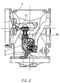
- FIG. 3 shows a gas-insulated in the region of the busbar High-voltage switchgear assembly to be arranged with a longitudinal separator designed as combined Separating grounding switch.
- the assignment of separation and Earthing switching path to the encapsulating housing 1 and the embodiment of the movable area of the disconnecting grounding switch 8 corresponds to the embodiment according to Figures 1 and 2.
- the only difference is the assignment of Phase conductor sections.
- the first phase conductor section ends 32 in the passage area of the encapsulating behind the self-shielding contact 63 of the isolating switching path, while a second phase conductor portion 33 is the passage region assigned; this phase conductor section 33 but is at the box-like part 81 of the outlet area assigned third phase conductor section 34 attached.
Landscapes
- Engineering & Computer Science (AREA)
- Power Engineering (AREA)
- Gas-Insulated Switchgears (AREA)
Description
- Figur 1
- den prinzipiellen Aufbau eines gemäß der Erfindung ausgestalteten Kapselungsbausteines,
- Figur 2
- eine detaillierte Darstellung einer gemäß der Erfindung ausgebildeten und für einen Kapselungsbaustein gemäß Figur 1 verwendeten kombinierten Trenn-Erdungs-Schaltstrecke und
- Figur 3
- einen Kapselungsbaustein, bei dem die Trennschaltstrecke des kombinierten Trenn-Erdungs-Schalters als Längstrenner dient.
Claims (7)
- Kombinierter Trenn-Erdungs-Schalter (6) zum Einbau in einen Kapselungsbaustein einer gasisolierten Hochspannungsschaltanlage, bestehend aus einem ersten Phasenleiterabschnitt (3) und einem zweiten Phasenleiterabschnitt (5) zur Bildung der Trenn-Schaltstrecke (61) und einem Erdungskontakt zur Bildung der Erdungs-Schaltstrecke (64) sowie einem linear verschiebbaren, in einem gehäuseartigen Teil des zweiten Phasenleiterabschnittes (5) geführten Schubkontaktstück, das mittels einer Schaltwelle (7) und eines an diese Schaltwelle (7) angekoppelten Getriebes verschiebbar ist,
wobei
die Erdungs-Schaltstrecke (64) unter einem Winkel (67) von 90 bis 150 ° zur Trenn-Schaltstrecke (61) angeordnet ist,
wobei das Schubkontaktstück in ein erstes Schubkontaktteil (53) für die Trennschaltstrecke und ein zweites Schubkontaktteil (55) für die Erdungs-Schaltstrecke unterteilt ist und die beiden Schubkontaktteile (53,55) jeweils über ein Koppelglied (74,75) an einen auf der Schaltwelle (7) aufsitzenden, einarmigen Schwenkhebel (71) angelenkt sind, dessen Schwenkachse mit Abstand (a1, a2) zu den beiden Achsen (62,65) der Schaltstrecken angeordnet ist. - Kombinierter Trenn-Erdungs-Schalter (6) nach Anspruch 1,
dadurch gekennzeichnet, daß die Abstände (a1,a2) der Schwenkachse etwa der Länge des einarmigen Schwenkhebels (71) entsprechen. - Kombinierter Trenn-Erdungs-Schalter (6) nach Anspruch 1 oder 2,
dadurch gekennzeichnet, daß das schwenkbare Ende des Schwenkhebels (71) T-förmig mit zwei in Schwenkrichtung hintereinander angeordneten Anlenkpunkten (72,73) für die beiden Koppelglieder (74,75) ausgebildet ist. - Kombinierter Trenn-Erdungs-Schalter (6) nach einem der Ansprüche 1 bis 3,
dadurch gekennzeichnet, daß jedes Schubkontaktteil (53,55) in einem rohrförmigen Gleitlager (52,54) geführt ist. - Kombinierter Trenn-Erdungs-Schalter (6) nach einem der Ansprüche 1 bis 4,
dadurch gekennzeichnet, daß das Schubkontaktteil für die Erdungs-Schaltstrecke (64) einen kleineren Durchmesser als das Schubkontaktteil für die Trenn-Schaltstrecke (61) aufweist. - Kombinierter Trenn-Erdungs-Schalter (6) nach einem der Ansprüche 1 bis 4,
dadurch gekennzeichnet, daß das Schubkontaktteil (55) der Erdungsschaltstrecke (64) einen aus einer Vielzahl von Kontaktfingern (56) bestehenden hohlzylindrischen Kontaktbereich aufweist, dem als Erdungskontakt ein pinartiges Kontaktstück (16) zugeordnet ist. - Kapselungsbaustein für eine gasisolierte Hochspannungsschaltanlage,
bestehend aus einem Kapselungsgehäuse mit einem eine Mittelachse (12) aufweisenden Durchgangsbereich (11) und einem senkrecht dazu verlaufenden, ebenfalls eine Mittelachse (14) aufweisenden Abgangsbereich (13) zur Aufnahme von wenigstens zwei Abschnitten eines Phasenleiters und eines diesen Phasenleiterabschnitten zugeordneten kombinierten Trenn-Erdungs-Schalters (6), wobeiwobeiwenigstens ein erster Phasenleiterabschnitt (3) dem Durchgangsbereich (11) und ein zweiter Phasenleiterabschnitt (5) dem Abgangsbereich (13) zugeordnet ist und der Trenn-Erdungs-Schalter (6) eine Trenn-Schaltstrecke (61) und eine Erdungs-Schaltstrecke (64) aufweistund der Erdungskontakt der Erdungs-Schaltstrecke (64) derart an der Innenwand des Kapselungsgehäuses angeordnet ist, daß die Mittelachse (65) der Erdungs-Schaltstrecke (64) unter einem Winkel zur Mittelachse (14) des Abgangsbereiches (13) verläuft,
der Trenn-Erdungs-Schalter (6) gemäß einem der Patentansprüche 1 bis 6 ausgebildet ist und
die Trenn-Schaltstrecke (61) parallel zur Mittelachse (14) des Abgangsbereiches (13) angeordnet ist.
Applications Claiming Priority (3)
| Application Number | Priority Date | Filing Date | Title |
|---|---|---|---|
| DE19825386A DE19825386C2 (de) | 1998-05-28 | 1998-05-28 | Kapselungsbaustein mit einem kombinierten Trenn-Erdungs-Schalter für eine gasisolierte Schaltanlage |
| DE19825386 | 1998-05-28 | ||
| PCT/DE1999/001571 WO1999062154A1 (de) | 1998-05-28 | 1999-05-25 | Kapselungsbaustein mit einem kombinierten trenn-erdungs-schalter für eine gasisolierte schaltanlage |
Publications (2)
| Publication Number | Publication Date |
|---|---|
| EP1082791A1 EP1082791A1 (de) | 2001-03-14 |
| EP1082791B1 true EP1082791B1 (de) | 2005-04-13 |
Family
ID=7870169
Family Applications (1)
| Application Number | Title | Priority Date | Filing Date |
|---|---|---|---|
| EP99936341A Expired - Lifetime EP1082791B1 (de) | 1998-05-28 | 1999-05-25 | Kombinierter trenn-erdungsschalter zum einbau in einen kapselungsbaustein einer gasisolierten schaltanlage und kapselungsbaustein mit einem eingebauten kombinierten trenn-erdungs-schalter |
Country Status (4)
| Country | Link |
|---|---|
| EP (1) | EP1082791B1 (de) |
| JP (1) | JP2002517151A (de) |
| DE (2) | DE19825386C2 (de) |
| WO (1) | WO1999062154A1 (de) |
Cited By (5)
| Publication number | Priority date | Publication date | Assignee | Title |
|---|---|---|---|---|
| EP2091057A1 (de) * | 2008-02-15 | 2009-08-19 | Kabushiki Kaisha Toshiba | Gasisolierte Schaltanlage und Montageverfahren dafür |
| FR2937175A1 (fr) * | 2008-10-14 | 2010-04-16 | Areva T & D Sa | Appareil de commutation electrique muni de deux interrupteurs, tels qu'un sectionneur de barre et un sectionneur de terre et comprenant des moyens d'entrainement communs des contacts mobiles des interrupteurs. |
| US8173927B2 (en) | 2008-10-14 | 2012-05-08 | Areva T&D Ag | High and medium voltage switch apparatus with two interrupters, having common means for actuating the movable contacts of the interrupters |
| DE102014205762A1 (de) | 2014-03-27 | 2015-10-15 | Siemens Aktiengesellschaft | Betriebsverfahren einer elektrischen Kontaktanordnung sowie elektrische Kontaktanordnung zur Durchführung des Betriebsverfahrens |
| EP4579710A1 (de) * | 2023-12-28 | 2025-07-02 | Henan Pinggao Electric Co., Ltd. | Dreistellungsschalter und gaskasten mit einem solchen schalter |
Families Citing this family (20)
| Publication number | Priority date | Publication date | Assignee | Title |
|---|---|---|---|---|
| DE29823222U1 (de) | 1998-12-23 | 1999-02-25 | Siemens AG, 80333 München | Gasisolierte, dreiphasig gekapselte Schaltanlage |
| DE10013232A1 (de) * | 2000-03-13 | 2001-09-20 | Siemens Ag | Mehrphasig gekapselte, gasiolierte Hochspannungsschalteinrichtung in Freiluftausführung |
| DE10219557A1 (de) * | 2002-04-26 | 2003-11-13 | Siemens Ag | Antriebseinheit bestehend aus einer isolierenden Schaltwelle und darauf aufgesetzten Mitnehmerelementen |
| WO2004032298A1 (ja) * | 2002-09-30 | 2004-04-15 | Mitsubishi Denki Kabushiki Kaisha | ガス絶縁開閉装置 |
| ATE337609T1 (de) * | 2004-02-27 | 2006-09-15 | Abb Technology Ag | Isoliertes erderschaltgerät für gasisolierte schaltanlagen |
| DE502004001795D1 (de) * | 2004-02-27 | 2006-11-30 | Abb Technology Ag | Kompaktes Erderschaltgerät für gasisolierte Schaltanlagen |
| JP4666487B2 (ja) * | 2005-09-06 | 2011-04-06 | 三菱電機株式会社 | ガス絶縁開閉装置 |
| DE102005061178A1 (de) * | 2005-12-21 | 2007-07-19 | Abb Technology Ag | Schaltanlage |
| DE102006033954A1 (de) * | 2006-07-22 | 2008-01-24 | Abb Technology Ag | Sammelschienenmodul für eine gasisolierte Hochspannungsschaltanlage |
| DE102009024938A1 (de) * | 2009-06-09 | 2010-12-16 | Siemens Aktiengesellschaft | Schaltgeräteanordnung |
| DE102009030608A1 (de) * | 2009-06-23 | 2010-12-30 | Siemens Aktiengesellschaft | Hochspannungsanordnung |
| DE102009030609A1 (de) * | 2009-06-23 | 2010-12-30 | Siemens Aktiengesellschaft | Hochspannungsanordnung |
| DE102009030610A1 (de) * | 2009-06-23 | 2010-12-30 | Siemens Aktiengesellschaft | Hochspannungsanordnung |
| DE102009036590B3 (de) * | 2009-08-07 | 2011-03-31 | Abb Technology Ag | Gasisolierte Hochspannungsschaltanlage |
| JP5471925B2 (ja) * | 2010-07-16 | 2014-04-16 | 株式会社日立製作所 | 接地開閉器付断路器 |
| EP2824686A1 (de) * | 2013-07-10 | 2015-01-14 | Siemens Aktiengesellschaft | Elektrische Hochspannungsschaltanordnung unter einer Metallschutzhülle |
| CN104332335A (zh) * | 2014-11-25 | 2015-02-04 | 正泰电气股份有限公司 | 一种快速接地开关 |
| CN104505279A (zh) * | 2014-12-25 | 2015-04-08 | 中国西电电气股份有限公司 | 三工位位置转换装置及基于该位置转换装置的隔离开关设备 |
| WO2017141060A1 (en) | 2016-02-18 | 2017-08-24 | Koncar - Elektricni Visokonaponski Aparati D.D. | Combined disconnecting-earthing switching module for a gas-insulated switchgear |
| CN112952408B (zh) * | 2021-02-09 | 2023-11-14 | 国网新疆电力有限公司阿克苏供电公司 | 可调角度的管形母线专用接地棒 |
Citations (1)
| Publication number | Priority date | Publication date | Assignee | Title |
|---|---|---|---|---|
| DE19511168A1 (de) * | 1995-03-28 | 1996-10-02 | Abb Management Ag | Schaltvorrichtung |
Family Cites Families (3)
| Publication number | Priority date | Publication date | Assignee | Title |
|---|---|---|---|---|
| NL159830B (nl) * | 1974-03-18 | 1979-03-15 | Coq Bv | Gesloten elektrische schakelinrichting voor hoge spanningen met in een gesloten keten in serie geschakelde schakelvel- den. |
| JPH0727748B2 (ja) * | 1989-07-05 | 1995-03-29 | 株式会社日立製作所 | ガス絶縁開閉装置 |
| DE19632574A1 (de) * | 1996-08-13 | 1998-02-19 | Abb Patent Gmbh | Trenn-Erderschalter für eine metallgekapselte, gasisolierte Hochspannungsschaltanlage |
-
1998
- 1998-05-28 DE DE19825386A patent/DE19825386C2/de not_active Expired - Fee Related
-
1999
- 1999-05-25 WO PCT/DE1999/001571 patent/WO1999062154A1/de not_active Ceased
- 1999-05-25 DE DE59911917T patent/DE59911917D1/de not_active Expired - Lifetime
- 1999-05-25 EP EP99936341A patent/EP1082791B1/de not_active Expired - Lifetime
- 1999-05-25 JP JP2000551464A patent/JP2002517151A/ja active Pending
Patent Citations (1)
| Publication number | Priority date | Publication date | Assignee | Title |
|---|---|---|---|---|
| DE19511168A1 (de) * | 1995-03-28 | 1996-10-02 | Abb Management Ag | Schaltvorrichtung |
Cited By (8)
| Publication number | Priority date | Publication date | Assignee | Title |
|---|---|---|---|---|
| EP2091057A1 (de) * | 2008-02-15 | 2009-08-19 | Kabushiki Kaisha Toshiba | Gasisolierte Schaltanlage und Montageverfahren dafür |
| FR2937175A1 (fr) * | 2008-10-14 | 2010-04-16 | Areva T & D Sa | Appareil de commutation electrique muni de deux interrupteurs, tels qu'un sectionneur de barre et un sectionneur de terre et comprenant des moyens d'entrainement communs des contacts mobiles des interrupteurs. |
| EP2178100A1 (de) | 2008-10-14 | 2010-04-21 | Areva T&D Sas | Elektrisches Schaltgerät, das mit zwei Schaltern ausgerüstet ist, wie etwa einem Sammelschienentrennschalter und einem Erdungstrenner, einschließlich der gemeinsamen Antriebsmittel der mobilen Kontakte der Schalter |
| US8173927B2 (en) | 2008-10-14 | 2012-05-08 | Areva T&D Ag | High and medium voltage switch apparatus with two interrupters, having common means for actuating the movable contacts of the interrupters |
| US8389884B2 (en) | 2008-10-14 | 2013-03-05 | Areva T & D Sas | Electrical switch apparatus having two interrupters, such as a busbar disconnector and a grounding disconnector, and including common actuator means for the movable contacts of the interrupters |
| RU2516446C2 (ru) * | 2008-10-14 | 2014-05-20 | Альстом Текнолоджи Лтд | Электрическое устройство переключения, содержащее два прерывателя, таких как шинный разъединитель и заземляющий разъединитель, и содержащее общее исполнительное устройство для подвижных контактов прерывателей |
| DE102014205762A1 (de) | 2014-03-27 | 2015-10-15 | Siemens Aktiengesellschaft | Betriebsverfahren einer elektrischen Kontaktanordnung sowie elektrische Kontaktanordnung zur Durchführung des Betriebsverfahrens |
| EP4579710A1 (de) * | 2023-12-28 | 2025-07-02 | Henan Pinggao Electric Co., Ltd. | Dreistellungsschalter und gaskasten mit einem solchen schalter |
Also Published As
| Publication number | Publication date |
|---|---|
| WO1999062154A1 (de) | 1999-12-02 |
| DE19825386C2 (de) | 2000-05-11 |
| JP2002517151A (ja) | 2002-06-11 |
| DE59911917D1 (de) | 2005-05-19 |
| EP1082791A1 (de) | 2001-03-14 |
| DE19825386A1 (de) | 1999-12-09 |
Similar Documents
| Publication | Publication Date | Title |
|---|---|---|
| DE19825386C2 (de) | Kapselungsbaustein mit einem kombinierten Trenn-Erdungs-Schalter für eine gasisolierte Schaltanlage | |
| EP0744803B1 (de) | Trenner für eine metallgekapselte gasisolierte Hochspannungschaltanlage | |
| EP0735637A2 (de) | Schaltvorrichtung mit einem geerdeten, isoliergasgefüllten Metallgehäuse | |
| EP0069693B1 (de) | Zylindrischer Behölter für eine dreipolige metallgekapselte, druckgasisolierte Hochspannungsschaltanlage | |
| EP1149446B1 (de) | Gekapselter hochspannungs-leistungsschalter in horizontal liegender bauweise | |
| EP1149445B1 (de) | Mehrphasig gekapselte freiluft-hochspannungsschalteinrichtung | |
| EP0678955B1 (de) | Metallgekapselte gasisolierte Schaltanlage | |
| EP1249910B1 (de) | Hochspannungs-Leistungsschalter für eine druckgasisolierte Schaltanlage | |
| DE3417299A1 (de) | Metallgekapselte, gasisolierte schaltanlage | |
| DE3318344C2 (de) | Hochspannungsschaltanlage | |
| DE3521945A1 (de) | Trennschalter fuer eine metallgekapselte, druckgasisolierte hochspannungsschaltanlage | |
| DE4336951A1 (de) | Hochspannungsschaltgerät | |
| EP0678952A1 (de) | Trenner für eine metallgekapselte gasisolierte Hochspannungsschaltanlage | |
| EP0875971B1 (de) | Hochspannungsschaltanlage | |
| EP0012708B1 (de) | Mehrphasige, metallgekapselte, druckgasisolierte Schaltvorrichtung für Hochspannungsschaltanlagen | |
| DE10325681B3 (de) | Schalteranordnung | |
| DE2823056C2 (de) | ||
| DE19641391C1 (de) | Hochspannungsschaltanlage in Hybridbauweise | |
| EP0593902B2 (de) | Schaltanlage für Mittelspannung | |
| EP2146411A2 (de) | Sammelschienenkupplung für eine elektrische Schaltanlage | |
| DE29806211U1 (de) | Kapselungsbaustein für eine Hochspannungsschaltanlage | |
| EP0633587B1 (de) | Gekapselte, isoliergasgefüllte Mittelspannungsschaltzelle | |
| DE2847376C2 (de) | Ein- oder mehrpolige Trennschalteranordnung für gekapselte Schaltanlagen | |
| DE102004061277A1 (de) | Mehrphasiges Schaltgerät mit zumindest drei gleichartigen Unterbrechereinheiten | |
| EP0026433B1 (de) | Last- oder Leistungsschalter |
Legal Events
| Date | Code | Title | Description |
|---|---|---|---|
| PUAI | Public reference made under article 153(3) epc to a published international application that has entered the european phase |
Free format text: ORIGINAL CODE: 0009012 |
|
| 17P | Request for examination filed |
Effective date: 20001122 |
|
| AK | Designated contracting states |
Kind code of ref document: A1 Designated state(s): CH DE FR LI NL |
|
| 17Q | First examination report despatched |
Effective date: 20021125 |
|
| GRAP | Despatch of communication of intention to grant a patent |
Free format text: ORIGINAL CODE: EPIDOSNIGR1 |
|
| RTI1 | Title (correction) |
Free format text: COMBINED DISCONNECTING-EARTHING SWITCH FOR INSTALLATION IN AN ENCAPSULATION MODULE OF A GAS-INSULATED SWITCHGEAR AND ENCA |
|
| GRAS | Grant fee paid |
Free format text: ORIGINAL CODE: EPIDOSNIGR3 |
|
| GRAA | (expected) grant |
Free format text: ORIGINAL CODE: 0009210 |
|
| AK | Designated contracting states |
Kind code of ref document: B1 Designated state(s): CH DE FR LI NL |
|
| PG25 | Lapsed in a contracting state [announced via postgrant information from national office to epo] |
Ref country code: NL Free format text: LAPSE BECAUSE OF FAILURE TO SUBMIT A TRANSLATION OF THE DESCRIPTION OR TO PAY THE FEE WITHIN THE PRESCRIBED TIME-LIMIT Effective date: 20050413 |
|
| REG | Reference to a national code |
Ref country code: CH Ref legal event code: EP |
|
| REG | Reference to a national code |
Ref country code: CH Ref legal event code: NV Representative=s name: SIEMENS SCHWEIZ AG |
|
| REF | Corresponds to: |
Ref document number: 59911917 Country of ref document: DE Date of ref document: 20050519 Kind code of ref document: P |
|
| NLV1 | Nl: lapsed or annulled due to failure to fulfill the requirements of art. 29p and 29m of the patents act | ||
| PLBE | No opposition filed within time limit |
Free format text: ORIGINAL CODE: 0009261 |
|
| STAA | Information on the status of an ep patent application or granted ep patent |
Free format text: STATUS: NO OPPOSITION FILED WITHIN TIME LIMIT |
|
| ET | Fr: translation filed | ||
| 26N | No opposition filed |
Effective date: 20060116 |
|
| REG | Reference to a national code |
Ref country code: CH Ref legal event code: PCAR Free format text: SIEMENS SCHWEIZ AG;INTELLECTUAL PROPERTY FREILAGERSTRASSE 40;8047 ZUERICH (CH) |
|
| REG | Reference to a national code |
Ref country code: FR Ref legal event code: PLFP Year of fee payment: 18 |
|
| REG | Reference to a national code |
Ref country code: FR Ref legal event code: PLFP Year of fee payment: 19 |
|
| PGFP | Annual fee paid to national office [announced via postgrant information from national office to epo] |
Ref country code: FR Payment date: 20170526 Year of fee payment: 19 |
|
| REG | Reference to a national code |
Ref country code: CH Ref legal event code: PCOW Free format text: NEW ADDRESS: WERNER-VON-SIEMENS-STRASSE 1, 80333 MUENCHEN (DE) |
|
| PGFP | Annual fee paid to national office [announced via postgrant information from national office to epo] |
Ref country code: CH Payment date: 20170807 Year of fee payment: 19 Ref country code: DE Payment date: 20170721 Year of fee payment: 19 |
|
| REG | Reference to a national code |
Ref country code: DE Ref legal event code: R119 Ref document number: 59911917 Country of ref document: DE |
|
| REG | Reference to a national code |
Ref country code: CH Ref legal event code: PL |
|
| PG25 | Lapsed in a contracting state [announced via postgrant information from national office to epo] |
Ref country code: LI Free format text: LAPSE BECAUSE OF NON-PAYMENT OF DUE FEES Effective date: 20180531 Ref country code: CH Free format text: LAPSE BECAUSE OF NON-PAYMENT OF DUE FEES Effective date: 20180531 |
|
| PG25 | Lapsed in a contracting state [announced via postgrant information from national office to epo] |
Ref country code: DE Free format text: LAPSE BECAUSE OF NON-PAYMENT OF DUE FEES Effective date: 20181201 Ref country code: FR Free format text: LAPSE BECAUSE OF NON-PAYMENT OF DUE FEES Effective date: 20180531 |