EP4579710A1 - Dreistellungsschalter und gaskasten mit einem solchen schalter - Google Patents
Dreistellungsschalter und gaskasten mit einem solchen schalter Download PDFInfo
- Publication number
- EP4579710A1 EP4579710A1 EP24202617.7A EP24202617A EP4579710A1 EP 4579710 A1 EP4579710 A1 EP 4579710A1 EP 24202617 A EP24202617 A EP 24202617A EP 4579710 A1 EP4579710 A1 EP 4579710A1
- Authority
- EP
- European Patent Office
- Prior art keywords
- grounding
- contact
- support seat
- isolating
- insulating
- Prior art date
- Legal status (The legal status is an assumption and is not a legal conclusion. Google has not performed a legal analysis and makes no representation as to the accuracy of the status listed.)
- Granted
Links
Images


Classifications
-
- H—ELECTRICITY
- H01—ELECTRIC ELEMENTS
- H01H—ELECTRIC SWITCHES; RELAYS; SELECTORS; EMERGENCY PROTECTIVE DEVICES
- H01H33/00—High-tension or heavy-current switches with arc-extinguishing or arc-preventing means
- H01H33/60—Switches wherein the means for extinguishing or preventing the arc do not include separate means for obtaining or increasing flow of arc-extinguishing fluid
- H01H33/66—Vacuum switches
- H01H33/666—Operating arrangements
- H01H33/6661—Combination with other type of switch, e.g. for load break switches
-
- H—ELECTRICITY
- H01—ELECTRIC ELEMENTS
- H01H—ELECTRIC SWITCHES; RELAYS; SELECTORS; EMERGENCY PROTECTIVE DEVICES
- H01H33/00—High-tension or heavy-current switches with arc-extinguishing or arc-preventing means
- H01H33/02—Details
-
- H—ELECTRICITY
- H01—ELECTRIC ELEMENTS
- H01H—ELECTRIC SWITCHES; RELAYS; SELECTORS; EMERGENCY PROTECTIVE DEVICES
- H01H1/00—Contacts
- H01H1/12—Contacts characterised by the manner in which co-operating contacts engage
- H01H1/36—Contacts characterised by the manner in which co-operating contacts engage by sliding
- H01H1/38—Plug-and-socket contacts
-
- H—ELECTRICITY
- H01—ELECTRIC ELEMENTS
- H01H—ELECTRIC SWITCHES; RELAYS; SELECTORS; EMERGENCY PROTECTIVE DEVICES
- H01H31/00—Air-break switches for high tension without arc-extinguishing or arc-preventing means
- H01H31/003—Earthing switches
-
- H—ELECTRICITY
- H01—ELECTRIC ELEMENTS
- H01H—ELECTRIC SWITCHES; RELAYS; SELECTORS; EMERGENCY PROTECTIVE DEVICES
- H01H31/00—Air-break switches for high tension without arc-extinguishing or arc-preventing means
- H01H31/02—Details
- H01H31/026—Movable parts and contacts mounted thereon
-
- H—ELECTRICITY
- H01—ELECTRIC ELEMENTS
- H01H—ELECTRIC SWITCHES; RELAYS; SELECTORS; EMERGENCY PROTECTIVE DEVICES
- H01H31/00—Air-break switches for high tension without arc-extinguishing or arc-preventing means
- H01H31/02—Details
- H01H31/04—Interlocking mechanisms
- H01H31/10—Interlocking mechanisms for interlocking two or more switches
-
- H—ELECTRICITY
- H01—ELECTRIC ELEMENTS
- H01H—ELECTRIC SWITCHES; RELAYS; SELECTORS; EMERGENCY PROTECTIVE DEVICES
- H01H31/00—Air-break switches for high tension without arc-extinguishing or arc-preventing means
- H01H31/26—Air-break switches for high tension without arc-extinguishing or arc-preventing means with movable contact that remains electrically connected to one line in open position of switch
- H01H31/32—Air-break switches for high tension without arc-extinguishing or arc-preventing means with movable contact that remains electrically connected to one line in open position of switch with rectilinearly-movable contact
-
- H—ELECTRICITY
- H01—ELECTRIC ELEMENTS
- H01H—ELECTRIC SWITCHES; RELAYS; SELECTORS; EMERGENCY PROTECTIVE DEVICES
- H01H33/00—High-tension or heavy-current switches with arc-extinguishing or arc-preventing means
- H01H33/02—Details
- H01H33/04—Means for extinguishing or preventing arc between current-carrying parts
- H01H33/12—Auxiliary contacts on to which the arc is transferred from the main contacts
- H01H33/121—Load break switches
- H01H33/122—Load break switches both breaker and sectionaliser being enclosed, e.g. in SF6-filled container
-
- H—ELECTRICITY
- H01—ELECTRIC ELEMENTS
- H01H—ELECTRIC SWITCHES; RELAYS; SELECTORS; EMERGENCY PROTECTIVE DEVICES
- H01H33/00—High-tension or heavy-current switches with arc-extinguishing or arc-preventing means
- H01H33/02—Details
- H01H33/42—Driving mechanisms
-
- H—ELECTRICITY
- H01—ELECTRIC ELEMENTS
- H01H—ELECTRIC SWITCHES; RELAYS; SELECTORS; EMERGENCY PROTECTIVE DEVICES
- H01H33/00—High-tension or heavy-current switches with arc-extinguishing or arc-preventing means
- H01H33/02—Details
- H01H33/46—Interlocking mechanisms
- H01H33/52—Interlocking mechanisms for interlocking two or more switches
-
- H—ELECTRICITY
- H01—ELECTRIC ELEMENTS
- H01H—ELECTRIC SWITCHES; RELAYS; SELECTORS; EMERGENCY PROTECTIVE DEVICES
- H01H33/00—High-tension or heavy-current switches with arc-extinguishing or arc-preventing means
- H01H33/60—Switches wherein the means for extinguishing or preventing the arc do not include separate means for obtaining or increasing flow of arc-extinguishing fluid
- H01H33/66—Vacuum switches
- H01H33/664—Contacts; Arc-extinguishing means, e.g. arcing rings
-
- H—ELECTRICITY
- H02—GENERATION; CONVERSION OR DISTRIBUTION OF ELECTRIC POWER
- H02B—BOARDS, SUBSTATIONS OR SWITCHING ARRANGEMENTS FOR THE SUPPLY OR DISTRIBUTION OF ELECTRIC POWER
- H02B13/00—Arrangement of switchgear in which switches are enclosed in, or structurally associated with, a casing, e.g. cubicle
- H02B13/02—Arrangement of switchgear in which switches are enclosed in, or structurally associated with, a casing, e.g. cubicle with metal casing
- H02B13/035—Gas-insulated switchgear
- H02B13/0354—Gas-insulated switchgear comprising a vacuum switch
-
- H—ELECTRICITY
- H01—ELECTRIC ELEMENTS
- H01H—ELECTRIC SWITCHES; RELAYS; SELECTORS; EMERGENCY PROTECTIVE DEVICES
- H01H33/00—High-tension or heavy-current switches with arc-extinguishing or arc-preventing means
- H01H33/02—Details
- H01H33/53—Cases; Reservoirs, tanks, piping or valves, for arc-extinguishing fluid; Accessories therefor, e.g. safety arrangements, pressure relief devices
- H01H33/56—Gas reservoirs
- H01H2033/566—Avoiding the use of SF6
Definitions
- the present invention relates to the field of manufacturing medium-voltage ring network distribution switch devices, and in particular, to a three-position switch and a gas box using the switch.
- a three-position switch and a vacuum circuit breaker switch on a line side are generally used.
- the three-position switch needs to have the ability of closing a grounding short-circuit current.
- An SF 6 gas-insulated three-position switch is mostly a rotary-blade three-position switch.
- a moving isolating contact and a moving grounding contact share a moving contact.
- a moving contact blade needs to not only enable a current to flow through a main electrically-conductive loop, but also realize closing of the grounding short-circuit current.
- the SF 6 is a non-environmentally-friendly greenhouse gas, and is gradually replaced by an environmentally-friendly gas.
- Arc extinguishing performance and insulating performance of the environmentally-friendly gas are much lower than those of the SF 6 gas. Therefore, if the SF 6 gas-insulated three-position switch solution is directly used, a long pre-breakdown time and a long arc time are caused when the grounding short-circuit current is closed. After the grounding short-circuit current is closed, the contact is seriously ablated, resistance of a main circuit is often greater than 20%, and a flow capacity cannot meet a requirement. Moreover, the moving contact is ablated by an arc after closing the grounding short-circuit current, causing electric field distortion and affecting insulating between clearances.
- a line-side three-position environmentally-friendly circuit breaker cabinet solution has two main technical routes.
- One is to use an SF 6 gas-insulated rotary-blade three-position switch solution, which is to improve closing performance by taking measures such as increasing a length of a moving contact blade and increasing a closing speed.
- the other is to connect a vacuum arc-extinguishing chamber in series on a side of a fixed grounding contact, and close the grounding short-circuit current through the arc-extinguishing chamber.
- the invention patent CN106486913A discloses an "environmentally-friendly gas-insulated ring main unit", including a vacuum circuit breaker switch with horizontally arranged poles, a rotary-blade three-position switch, and the like. To meet the insulating performance, a moving contact blade of the three-position switch is lengthened, and a clearance spacing is increased. In addition, the moving contact blade is insulated and coated, but an end portion of the moving contact blade needs to perform electrical contact and is not completely covered.
- the invention patent with a publication number CN108321001A discloses a "three-position switch", including a fixed isolating contact connected to a vacuum arc-extinguishing chamber of a circuit breaker, a fixed grounding contact connected to a grounding vacuum arc-extinguishing chamber, an isolation breaker, and the like.
- the isolation breaker first contacts the fixed grounding contact, and then the grounding vacuum arc-extinguishing chamber is closed to close the grounding short-circuit current.
- the isolation breaker contacts the fixed grounding contact at an isolation position, and a vacuum clearance is used between the isolation breaker and the ground instead of a gas clearance, which poses a potential safety hazard.
- a vacuum arc-extinguishing chamber is added to a grounding circuit to close the grounding short-circuit current, and on the other hand, a transmission device is added to a three-position structure to drive a grounding arc-extinguishing chamber to close.
- the solution has a complex structure and high costs.
- an objective of the present invention is to provide a three-position switch and a gas box using the switch.
- a three-position switch includes:
- the grounding support seat of the three-position switch is electrically connected to an ingoing/outgoing line bushing through a branch bus.
- the insulating driving crank arm forms a first crank slider structure with the moving isolating contact through a first insulating connecting rod;
- the insulating driving crank arm forms a second crank slider structure with the moving grounding contact through a second insulating connecting rod.
- the moving grounding contact adopts a petal-like self-elastic contact, with a reduced-diameter end.
- the fixed grounding contact is inserted into the moving grounding contact, and a petal-like contact finger of the moving grounding contact deforms outward to generate a contact pressure to ensure reliable contact.
- an end portion of the isolating support seat close to the first spring contact finger is provided with an arc surface for a uniform electric field, and a first notch for the first spring contact finger to be mounted is provided.
- an end portion of the grounding support seat close to the second spring contact finger is provided with an arc surface for a uniform electric field, and a second notch for the second spring contact finger to be mounted is provided.
- an end portion of the grounding shielding cover toward the grounding support seat is provided with an arc surface for a uniform electric field.
- an acute angle is formed between the axis of the isolating support seat and the axis of the grounding support seat.
- the acute angle is an angle greater than 0° and less than 90° (a right angle).
- a gas box is provided.
- the three-position switch is arranged in the gas box, and the three-position switch is fixed to a front plate of the gas box and arranged exactly below a vacuum circuit breaker.
- An axis of the isolating support seat of the three-position switch coincides with an axis center of a fixed isolating contact seat.
- a top portion of the gas box is provided with the vacuum circuit breaker and a connected side expansion bus bushing, a moving end of a vacuum arc-extinguishing chamber is electrically connected to the side expansion bus bushing through a flexible connection, and the fixed isolating contact seat is fixed to a fixed end of the vacuum arc-extinguishing chamber;
- an inside of the fixed isolating contact seat is connected to the fixed isolating contact by mounting a fixed isolating contact seat spring contact finger.
- An innovative fast direct-acting three-position switch is used, so that a moving grounding contact is separated from a moving isolating contact, and contact ablation after closing for grounding does not affect flow of a main circuit, thereby improving closing capacity.
- the moving isolating contact and the moving grounding contact are respectively shielded by a shielding cover, and arc ablation of the contact does not affect insulating performance of a clearance.
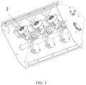
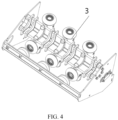
- a three-phase moving isolating contact and a three-phase moving grounding contact are simultaneously driven by a transmission shaft, thereby ensuring synchronization of three phases.
- orientation or position relation indicated by the terms “above”, “below”, “inside”, “outside”, “top/bottom end” are based on the orientation or position relation indicated on drawings, which are merely used for convenience and simplicity of description of the present invention, rather than indicating or implying that the referred device or component should necessarily have a specific orientation, construct and operate in a specific orientation. Therefore, the terms cannot be construed as a limitation on the present invention.
- first and second are only used to describe the objective, and cannot be understood as indicating or implying relatively significance.
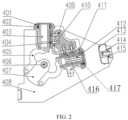
- a three-position switch shown in FIG. 1 to FIG. 4 includes a three-position insulating support 409. Two ends of the three-position insulating support 409 are fixed to a front plate and a rear plate of a switch frame 408.
- the three-position switch 4 is provided with an isolating support seat 401 and a grounding support seat 411 thereon, and the isolating support seat 401 is electrically and non-coaxially connected to the grounding support seat 411 through a connecting bar 410.
- An acute angle is formed between the axis of the isolating support seat 401 and the axis of the grounding support seat 411.
- the acute angle is an angle greater than 0° and less than 90° (a right angle).
- a first insulating guide sleeve 404 is embedded in the isolating support seat 401.
- the moving isolating contact 403 extends into the isolating support seat 401 and moves along an axis of the isolating support seat 401, and is in electrical contact with the isolating support seat 401 through a first spring contact finger 402, and the remaining part is insulated and isolated from the isolating support seat 401 through the first insulating guide sleeve 404.
- An end portion of the isolating support seat 401 close to the first spring contact finger 402 is provided with an arc surface for a uniform electric field, and a first notch for the first spring contact finger 402 to be mounted is provided.
- a second insulating guide sleeve 416 is embedded in the grounding support seat 411, a moving grounding contact 412 extends into the grounding support seat 411 and moves along an axis of the grounding support seat 411, and is in conductive contact with the grounding support seat 411 through a second spring contact finger 417, and the remaining part is insulated and isolated from the grounding support seat 411 through the second insulating guide sleeve 416.
- the moving grounding contact 412 adopts a petal-like self-elastic contact, with a reduced-diameter end.
- the fixed grounding contact 414 is inserted into the moving grounding contact 412, and a petal-like contact finger of the moving grounding contact 412 deforms outward to generate a contact pressure to ensure reliable contact.
- An end portion of the grounding support seat 411 close to the second spring contact finger 417 is provided with an arc surface for a uniform electric field, and a second notch for the second spring contact finger 417 to be mounted is provided.
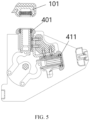
- the axis of the isolating support seat 401 of the three-position switch 4 is arranged to coincide with an axis center of a fixed isolating contact seat 101, and an insulating distance is provided between the isolating support seat 401 of the three-position switch 4 and the fixed isolating contact seat 101.
- Two ends of a three-position insulating spindle 406 are supported and mounted on the front plate and the rear plate of the switch frame 408, and rotatable along an axis of the switch frame 408, and the axis of the switch frame 408 passes through a point of intersection of the axes of the isolating support seat 401 and the grounding support seat 411.
- the grounding support seat 411 of the three-position switch 4 is electrically connected to an ingoing/outgoing line bushing 7 through a branch bus 6.
- An insulating driving crank arm 407 is fixed to the three-position insulating spindle 406 and rotates with the three-position insulating spindle 406, and the insulating driving crank arm 407 is respectively connected to the moving isolating contact 403 or the moving grounding contact 412 through an insulating connecting rod 405 to form a crank slider structure.
- the insulating driving crank arm 407 forms a first crank slider structure with the moving isolating contact 403 through a first insulating connecting rod.
- the insulating driving crank arm 407 forms a second crank slider structure with the moving grounding contact 412 through a second insulating connecting rod.
- the three-station operating mechanism drives the insulating driving crank arm 407 to rotate counterclockwise through the three-position insulating spindle 406, the insulating connecting rod 405 simultaneously drives the moving grounding contact 412 to move to the right along the axis of the grounding support seat 411 until the fixed grounding contact 414 is inserted into the moving grounding contact 412, and the insulating connecting rod 405 simultaneously drives the moving isolating contact 403 to move a short distance downward along the axis of the isolating support seat 401.
- the end portion of the moving isolating contact 403 is always hidden in the isolating support seat 401 and shielded by the electric field thereof.
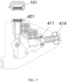
- a grounding state is shown in FIG. 7 .
- the moving grounding contact 412 is in conductive contact with the grounding support seat 411 through the first spring contact finger 402, and the moving grounding contact 412 is in conductive contact with the fixed grounding contact 414 through a petal-like contact finger.
Landscapes
- Engineering & Computer Science (AREA)
- Power Engineering (AREA)
- Gas-Insulated Switchgears (AREA)
Applications Claiming Priority (1)
| Application Number | Priority Date | Filing Date | Title |
|---|---|---|---|
| CN202311834935.5A CN117612888A (zh) | 2023-12-28 | 2023-12-28 | 一种三工位开关及使用该开关的气箱 |
Publications (3)
| Publication Number | Publication Date |
|---|---|
| EP4579710A1 true EP4579710A1 (de) | 2025-07-02 |
| EP4579710C0 EP4579710C0 (de) | 2026-03-18 |
| EP4579710B1 EP4579710B1 (de) | 2026-03-18 |
Family
ID=89953716
Family Applications (1)
| Application Number | Title | Priority Date | Filing Date |
|---|---|---|---|
| EP24202617.7A Active EP4579710B1 (de) | 2023-12-28 | 2024-09-25 | Dreistellungsschalter und gaskasten mit einem solchen schalter |
Country Status (2)
| Country | Link |
|---|---|
| EP (1) | EP4579710B1 (de) |
| CN (1) | CN117612888A (de) |
Cited By (1)
| Publication number | Priority date | Publication date | Assignee | Title |
|---|---|---|---|---|
| CN114843924A (zh) * | 2022-05-25 | 2022-08-02 | 广东正超电气有限公司 | 一种常压密封空气绝缘开关设备 |
Families Citing this family (2)
| Publication number | Priority date | Publication date | Assignee | Title |
|---|---|---|---|---|
| WO2025246545A1 (zh) * | 2024-05-30 | 2025-12-04 | 厦门华电开关有限公司 | 用于环网柜之间电连接的主母排结构及环网供电系统 |
| CN120453920A (zh) * | 2025-07-09 | 2025-08-08 | 常州博瑞电力自动化设备有限公司 | 一种小型化40.5kV环网柜气箱及其环网柜 |
Citations (6)
| Publication number | Priority date | Publication date | Assignee | Title |
|---|---|---|---|---|
| EP1082791B1 (de) * | 1998-05-28 | 2005-04-13 | Siemens Aktiengesellschaft | Kombinierter trenn-erdungsschalter zum einbau in einen kapselungsbaustein einer gasisolierten schaltanlage und kapselungsbaustein mit einem eingebauten kombinierten trenn-erdungs-schalter |
| CN102339684A (zh) * | 2010-07-16 | 2012-02-01 | 日本Ae帕瓦株式会社 | 带有接地开闭器的断路器 |
| EP2446453B1 (de) * | 2009-06-23 | 2016-11-30 | Siemens Aktiengesellschaft | Sichtfenster und erdungskontaktanschluss für eine hochspannungsanordnung |
| CN106486913A (zh) | 2015-08-31 | 2017-03-08 | 河北电力装备有限公司 | 一种环保气体绝缘环网柜 |
| CN108321001A (zh) | 2018-02-09 | 2018-07-24 | 浙江华仪电器科技有限公司 | 一种三工位开关 |
| CN109412067A (zh) * | 2018-11-02 | 2019-03-01 | 北京双杰电气股份有限公司 | 环保气体绝缘开关柜 |
-
2023
- 2023-12-28 CN CN202311834935.5A patent/CN117612888A/zh active Pending
-
2024
- 2024-09-25 EP EP24202617.7A patent/EP4579710B1/de active Active
Patent Citations (6)
| Publication number | Priority date | Publication date | Assignee | Title |
|---|---|---|---|---|
| EP1082791B1 (de) * | 1998-05-28 | 2005-04-13 | Siemens Aktiengesellschaft | Kombinierter trenn-erdungsschalter zum einbau in einen kapselungsbaustein einer gasisolierten schaltanlage und kapselungsbaustein mit einem eingebauten kombinierten trenn-erdungs-schalter |
| EP2446453B1 (de) * | 2009-06-23 | 2016-11-30 | Siemens Aktiengesellschaft | Sichtfenster und erdungskontaktanschluss für eine hochspannungsanordnung |
| CN102339684A (zh) * | 2010-07-16 | 2012-02-01 | 日本Ae帕瓦株式会社 | 带有接地开闭器的断路器 |
| CN106486913A (zh) | 2015-08-31 | 2017-03-08 | 河北电力装备有限公司 | 一种环保气体绝缘环网柜 |
| CN108321001A (zh) | 2018-02-09 | 2018-07-24 | 浙江华仪电器科技有限公司 | 一种三工位开关 |
| CN109412067A (zh) * | 2018-11-02 | 2019-03-01 | 北京双杰电气股份有限公司 | 环保气体绝缘开关柜 |
Cited By (1)
| Publication number | Priority date | Publication date | Assignee | Title |
|---|---|---|---|---|
| CN114843924A (zh) * | 2022-05-25 | 2022-08-02 | 广东正超电气有限公司 | 一种常压密封空气绝缘开关设备 |
Also Published As
| Publication number | Publication date |
|---|---|
| CN117612888A (zh) | 2024-02-27 |
| EP4579710C0 (de) | 2026-03-18 |
| EP4579710B1 (de) | 2026-03-18 |
Similar Documents
| Publication | Publication Date | Title |
|---|---|---|
| EP4579710B1 (de) | Dreistellungsschalter und gaskasten mit einem solchen schalter | |
| CN102403668B (zh) | 一种高压组合电器 | |
| CN115602480B (zh) | 三工位开关及三工位环保气体组合电器环网柜 | |
| CN107731619A (zh) | 一种高海拔户内高压交流组合式真空断路器 | |
| CN116313622A (zh) | 一种联动开关及断路器柜 | |
| CN102176396B (zh) | 三相共箱式快速接地开关装置 | |
| CN115000866B (zh) | 环网柜 | |
| CN111540641A (zh) | 用于洁净干燥空气绝缘金属封闭开关设备的负荷开关 | |
| CN209217565U (zh) | 一种绝缘开关设备 | |
| CN103681092B (zh) | 固体绝缘隔离接地开关装置及其固封单元 | |
| CN112768287A (zh) | 一种带有三工位隔离开关的充气柜断路器 | |
| CN116741565A (zh) | 一种三工位隔离开关装置以及充气柜 | |
| CN204270968U (zh) | 一种多断口高压真空断路器的双断口真空开关模块 | |
| CN109510098A (zh) | 一种绝缘开关设备 | |
| CN210897118U (zh) | 双电源固封断路器 | |
| CN219321241U (zh) | 双模式永磁断路器 | |
| CN220306148U (zh) | 一种三工位隔离开关装置以及充气柜 | |
| CN210091970U (zh) | 一种小型化隔离开关机构 | |
| CN207353154U (zh) | 一种高海拔户内高压交流组合式真空断路器 | |
| CN222380483U (zh) | 一种高压断路器 | |
| CN216161638U (zh) | 一种充气柜隔离装置 | |
| KR20010106810A (ko) | 가스절연 개폐기의 단로기 | |
| CN219066695U (zh) | 常压空气柜断路器开关 | |
| CN207038415U (zh) | 用于高压断路器的传动机构 | |
| CN114512365A (zh) | 一种三相共箱式快速接地开关 |
Legal Events
| Date | Code | Title | Description |
|---|---|---|---|
| PUAI | Public reference made under article 153(3) epc to a published international application that has entered the european phase |
Free format text: ORIGINAL CODE: 0009012 |
|
| STAA | Information on the status of an ep patent application or granted ep patent |
Free format text: STATUS: THE APPLICATION HAS BEEN PUBLISHED |
|
| STAA | Information on the status of an ep patent application or granted ep patent |
Free format text: STATUS: REQUEST FOR EXAMINATION WAS MADE |
|
| AK | Designated contracting states |
Kind code of ref document: A1 Designated state(s): AL AT BE BG CH CY CZ DE DK EE ES FI FR GB GR HR HU IE IS IT LI LT LU LV MC ME MK MT NL NO PL PT RO RS SE SI SK SM TR |
|
| 17P | Request for examination filed |
Effective date: 20250604 |
|
| RIN1 | Information on inventor provided before grant (corrected) |
Inventor name: CAO, YEFEI Inventor name: QIAN, LIXIAO Inventor name: PAN, JIAN Inventor name: ZHANG, JIAFEI Inventor name: ZHAI, TINGTING Inventor name: LIU, ZHIYANG Inventor name: ZHANG, HAO Inventor name: FEI, XIANG Inventor name: FENG, XIANGWEI Inventor name: LU, JIAN Inventor name: ZHU, YANQING Inventor name: WANG, HAIYAN Inventor name: ZHU, ZHIHAO Inventor name: LOU, YUANTONG |
|
| GRAP | Despatch of communication of intention to grant a patent |
Free format text: ORIGINAL CODE: EPIDOSNIGR1 |
|
| STAA | Information on the status of an ep patent application or granted ep patent |
Free format text: STATUS: GRANT OF PATENT IS INTENDED |
|
| RIC1 | Information provided on ipc code assigned before grant |
Ipc: H01H 31/00 20060101AFI20251001BHEP Ipc: H01H 31/32 20060101ALI20251001BHEP Ipc: H01H 33/12 20060101ALI20251001BHEP Ipc: H01H 33/666 20060101ALI20251001BHEP Ipc: H01H 1/38 20060101ALI20251001BHEP Ipc: H01H 33/56 20060101ALN20251001BHEP |
|
| INTG | Intention to grant announced |
Effective date: 20251014 |
|
| GRAS | Grant fee paid |
Free format text: ORIGINAL CODE: EPIDOSNIGR3 |
|
| GRAA | (expected) grant |
Free format text: ORIGINAL CODE: 0009210 |
|
| STAA | Information on the status of an ep patent application or granted ep patent |
Free format text: STATUS: THE PATENT HAS BEEN GRANTED |
|
| AK | Designated contracting states |
Kind code of ref document: B1 Designated state(s): AL AT BE BG CH CY CZ DE DK EE ES FI FR GB GR HR HU IE IS IT LI LT LU LV MC ME MK MT NL NO PL PT RO RS SE SI SK SM TR |
|
| REG | Reference to a national code |
Ref country code: CH Ref legal event code: F10 Free format text: ST27 STATUS EVENT CODE: U-0-0-F10-F00 (AS PROVIDED BY THE NATIONAL OFFICE) Effective date: 20260318 Ref country code: GB Ref legal event code: FG4D |
|
| REG | Reference to a national code |
Ref country code: IE Ref legal event code: FG4D |
|
| U01 | Request for unitary effect filed |
Effective date: 20260324 |
|
| U07 | Unitary effect registered |
Designated state(s): AT BE BG DE DK EE FI FR IT LT LU LV MT NL PT RO SE SI Effective date: 20260330 |