EP1081800A2 - Elektrischer Verbinder - Google Patents
Elektrischer Verbinder Download PDFInfo
- Publication number
- EP1081800A2 EP1081800A2 EP00112256A EP00112256A EP1081800A2 EP 1081800 A2 EP1081800 A2 EP 1081800A2 EP 00112256 A EP00112256 A EP 00112256A EP 00112256 A EP00112256 A EP 00112256A EP 1081800 A2 EP1081800 A2 EP 1081800A2
- Authority
- EP
- European Patent Office
- Prior art keywords
- locking
- locking ring
- connector part
- connector
- ring
- Prior art date
- Legal status (The legal status is an assumption and is not a legal conclusion. Google has not performed a legal analysis and makes no representation as to the accuracy of the status listed.)
- Granted
Links
Images

Classifications
-
- H—ELECTRICITY
- H01—ELECTRIC ELEMENTS
- H01R—ELECTRICALLY-CONDUCTIVE CONNECTIONS; STRUCTURAL ASSOCIATIONS OF A PLURALITY OF MUTUALLY-INSULATED ELECTRICAL CONNECTING ELEMENTS; COUPLING DEVICES; CURRENT COLLECTORS
- H01R13/00—Details of coupling devices of the kinds covered by groups H01R12/70 or H01R24/00 - H01R33/00
- H01R13/62—Means for facilitating engagement or disengagement of coupling parts or for holding them in engagement
- H01R13/627—Snap or like fastening
- H01R13/6275—Latching arms not integral with the housing
Definitions
- the invention relates to an electrical connector with a first connector part, a locking ring which is provided on the first connector part and has at least one locking element, a locking ring, the relative to the locking ring from a locking position to an unlocking position is movable, and a second connector part, which with the Locking element of the locking ring can be brought into a locking engagement, the Locking ring in the locking position the locking element in the Locking engagement with the second connector part holds, and wherein the second connector part is only detachable from the first connector part when the Locking ring is in the unlocked position.
- Such a connector enables an electrical connection between complementary electrical contact elements that on the two connector parts are provided.
- the locking ring is capable of this locking connection against unintentional Unlock lock.
- the locking ring must be against the bias from the locked position in the unlocking position can be moved, thereby the locking element release the locking ring.
- This task is for an electrical connector of the type mentioned Art solved in that the locking ring when it is in his Unlocked position is moved, the locking element of the locking ring in one Release position holds in which the locking element out of engagement with the second connector part is.
- the locking element not only for releasing its locking connection with the second connector part passively released, but becomes active from the locking engagement with pushed back the second connector part in the release position or pulled and held there.
- the snap connection between the locking element and the second connector part already with the movement the locking ring actively released into its unlocked position.
- Connector continues a controlled and safe manufacturing the connection between the two connector parts.
- the second This is because the connector part can then also be connected to the first connector part if the locking ring is loose due to the preload is in the locked position. In this case it is immediately after Ensuring the connection between the two connector parts, that the connection is not unintentionally broken.
- the invention enables the two connector parts to connect with less effort than known ones electrical connector is the case.
- the second Connector part on the first connector part can namely the locking ring be brought into the unlocked position in order to thereby a premature locking engagement of the locking ring with the second connector part to prevent.
- Establishing the snap connection between the locking ring and the second connector part and securing this locking connection is only done after the second connector part without raised Force already connected to the first connector part has, for example, been inserted into it.
- locking elements can be used in suitable on the locking ring Distances may be provided, especially in one another paired or symmetrical arrangement.
- locking ring and “locking ring” not to be interpreted as meaning that the invention relates to an electrical Connector is limited, the components of which are round in cross section have to. Instead, the first connector part, the second connector part, the locking ring and the locking ring any, for example have a square or rectangular cross section.
- a positive control element for example in the form of a sloping edge or surface, provided when moving the locking ring from the locked position to the unlocked position Locking elements of the locking ring to release their respective locking connection caused with the second connector part.
- a positive control element for example in the form of a sloping edge or surface, provided when moving the locking ring from the locked position to the unlocked position Locking elements of the locking ring to release their respective locking connection caused with the second connector part.
- the locking elements of the locking ring each have one spring-back pivotable locking bracket, locking arm and / or a spring-back have rotatable locking head.
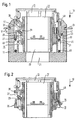
- FIG. 1 the electrical shown in the figures Connector a base housing serving as the first connector part 11, a locking ring 13, a locking ring 15 and one as the second Connector part serving socket 17, each sleeve-shaped surrounded from the outside in and each made of plastic are.
- an insertion direction 19 is shown in FIG following reference is made.
- the basic housing 11 and the receptacle 17 each have a central one Contact area 21 or 23, for receiving each other complementary contact elements is provided.
- the receptacle 17 has a locking web 25 on its outer circumference, the is chamfered on its underside pointing in the direction of insertion 19.
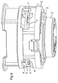
- the locking ring 15 has three resiliently pivotable along its circumference Locking bracket 27, which obliquely in the relaxed state are inclined on the outside and over the legs of a U-shape on the locking ring 15 are formed (see. Fig. 4).
- Locking bracket 27 Along the base of the U shape of the Locking bracket 27 is formed in each case a resiliently rotatable locking head 29.
- the top of the locking heads opposite the insertion direction 19 29 is chamfered.
- Each locking bracket 27 forms together with the locking head 29 formed thereon a locking element of the locking ring 15.
- the locking ring 15 also has three hooking lugs along its outer circumference 31, each on one on the inside of the basic housing 11 engage snap ring stop 33.
- the locking ring 13 has in the region of each locking head 29 of the locking ring 15 each have an associated one, formed by a hollow cylinder segment Locking section 35.
- Each locking section 35 against the insertion direction 19 adjacent, the locking ring 15 has a release recess 37 on, which are in the area of the respectively assigned locking head 29 of the locking ring 15 extends along the circumference of the locking ring 13.
- a positive control rib projects from the ends of each release recess 37 39 in the insertion direction 19 into the release recess 37 (see Fig. 5).
- the positive control ribs 39 have a reference the insertion direction 19 in the direction of the center of the locking ring 13 inclined positive control face 41.
- the locking ring 13 also has on it in the insertion direction 19th pointing underside 3 radially outward fastening hooks 43. These each protrude into the inner peripheral surface of the basic housing 11 trained axial sliding groove 45 into it, which is opposite to the direction of insertion 19 is limited by a fastening paragraph 47. Farther has the locking ring 13 radially on its inner peripheral surface insertion stops 48 set inwards.
- a coil spring 49 arranged in the insertion direction 19 on the bottom of the basic housing 11 and counter to the direction of insertion 19 rests on the underside of the locking ring 13.
- FIG. 1 part of a fastening plate 51 is shown in FIG. 1, in which the basic housing 11 is inserted.
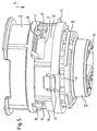
- FIG. 2 to 4 show the electrical connector according to FIG. 1 without Basic housing 11 and coil spring 49 and without mounting plate 51 in different positions of the locking ring 13, the locking ring 15th and the receptacle 17 relative to each other, as explained below becomes.
- 5 and 6 show the electrical connector of FIG. 1 also without basic housing 11 and coil spring 49 in different relative positions.
- 5 and 6 is an electrical contact insert 53 shown within the contact area 23 of the socket 17.
- the basic housing 11 is counter to the insertion direction 19 in an opening is inserted within the mounting plate 51 and there fixed by means of a holding mechanism, not shown.
- the pre-assembled unit of the basic housing 11, locking ring 15 and Locking ring 13 can now on the contact area 21 of the basic housing 11 are provided with electrical contact elements, and them is ready to receive the socket 17.
- the plug sleeve 17 is thus as shown in FIGS. 1 and 5 with the basic housing 11 plug-in.
- the socket 17 can no longer unintentionally from the unit of basic housing 11, locking ring 15 and Loosen locking ring 13, as opposed to movement of plug sleeve 17 of the insertion direction 19, the locking webs 25 on the locking heads 29.
- the locking heads 29 cannot oppose the above Rotate the explained rotational movement, since they are already on the back Locking sections 35 of the locking ring 13 abut and thus against a backward rotation are blocked.
- the unlocking position of the locking ring shown in FIG. 3 is 13 reached relative to the locking ring 15, in which the release recesses 37 of the locking ring 13 at the axial height of the locking heads 29 are located.
- the positive control ribs 39 therefor that the locking heads 29 with the locking brackets 27 from their relaxed position 1 and 2 pressed radially outward into the release position in which they are disengaged from the second connector part 17.
- This active radial pushing out occurs because the positive control ribs 39 with their positive control end faces 41 on the Base of the U-shape of the locking bracket 27 abut (Fig. 2 and 6), and that at further axial movement of the positive control ribs 39 or the locking ring 13 in the insertion direction 19, the locking bracket 27 along the Forced control faces 41 slide.
- Another advantage of the invention is that during insertion the plug sleeve 17 into the preassembled unit from the basic housing 11, Locking ring 15 and locking ring 13 of the increased contact pressure explained for rotating the locking heads 29 are not necessarily applied must, if the locking ring 13 pressed in the insertion direction 19 at the same time is and thus the locking bracket 27 actively moved radially outwards become.
- the locking ring 15 is not necessarily - as shown in the figures - a component separate from the basic housing 11 must be, but also be an integral part of the basic housing 11 can.
- a sealing ring be provided between the base housing 11 on the one hand and the Plug sleeve 17 and / or the locking ring 15 on the other hand.
Landscapes
- Details Of Connecting Devices For Male And Female Coupling (AREA)
Abstract
Description
- Fig. 1
- einen Mittenquerschnitt durch Teile eines erfindungsgemäßen elektrischen Verbinders, wobei der Verriegelungsring sich in der Verriegelungsstellung befindet,
- Fig. 2
- Teile des Verbinders gemäß Fig. 1, wobei der Verriegelungsring in die Entriegelungsstellung bewegt wird,
- Fig. 3
- Teile des Verbinders gemäß Fig. 1, wobei der Verriegelungsring sich in der Entriegelungsstellung befindet,
- Fig. 4
- Teile des Verbinders gemäß Fig. 1, wobei das zweite Verbinderteil aus dem Rastring herausgezogen ist,
- Fig. 5
- eine Perspektivansicht von Teilen des Verbinders gemäß Fig. 1, wobei der Verriegelungsring sich in der Verriegelungsstellung befindet, und
- Fig. 6
- eine Perspektivansicht von Teilen des Verbinders gemäß Fig. 1, wobei der Verriegelungsring in die Entriegelungsstellung bewegt wird.
- 11
- Grundgehäuse
- 13
- Verriegelungsring
- 15
- Rastring
- 17
- Steckhülse
- 19
- Einsteckrichtung
- 21
- Kontaktbereich
- 23
- Kontaktbereich
- 25
- Raststeg
- 27
- Rastbügel
- 29
- Rastkopf
- 31
- Einhaknase
- 33
- Rastringanschlag
- 35
- Sperrabschnitt
- 37
- Freigabeaussparung
- 39
- Zwangssteuerungsflügel
- 41
- Zwangssteuerungsstirnseite
- 43
- Befestigungshaken
- 45
- Schiebenut
- 47
- Befestigungsabsatz
- 48
- Einführanschlag
- 49
- Spiralfeder
- 51
- Befestigungsblech
- 53
- elektrischer Kontakteinsatz
Claims (9)
- Elektrischer Verbinder miteinem ersten Verbinderteil (11),einem Rastring (15), der an dem ersten Verbinderteil (11) vorgesehen ist und wenigstens ein Rastelement (27, 29) aufweist,einem Verriegelungsring (13), der relativ zu dem Rastring (15) von einer Verriegelungsstellung in eine Entriegelungsstellung bewegbar ist, undeinem zweiten Verbinderteil (17), das mit dem Rastelement (27, 29) des Rastrings (15) in einen Rasteingriff bringbar ist,
wobei der Verriegelungsring (13) in der Verriegelungsstellung das Rastelement (27, 29) in dem Rasteingriff mit dem zweiten Verbinderteil (17) hält, und
wobei das zweite Verbinderteil (17) lediglich dann von dem ersten Verbinderteil (11) lösbar ist, wenn der Verriegelungsring (13) sich in der Entriegelungsstellung befindet,
dadurch gekennzeichnet,daß der Verriegelungsring (13), wenn er in seine Entriegelungsstellung bewegt ist, das Rastelement (27, 29) des Rastrings (15) in einer Freigabestellung hält, in der das Rastelement (27, 29) außer Eingriff mit dem zweiten Verbinderteil (17) steht. - Verbinder nach Anspruch 1,
dadurch gekennzeichnet,daß der Verriegelungsring (13) wenigstens ein Zwangssteuerungselement (39) aufweist, durch das bei Überführen des Verriegelungsrings (13) von der Verriegelungsstellung in die Entriegelungsstellung der Rasteingriff des Rastelements (27, 29) mit dem zweiten Verbinderteil (17) lösbar ist. - Verbinder nach Anspruch 2,
dadurch gekennzeichnet,daß das Rastelement (27, 29) durch Beaufschlagung durch das Zwangssteuerungselement (39) aus dem Rasteingriff mit dem zweiten Verbinderteil (17) lösbar, insbesondere schwenkbar ist. - Verbinder nach einem der Ansprüche 2 oder 3,
dadurch gekennzeichnet,daß das Zwangssteuerungselement (39) eine axial bewegbare schräge Kante oder Fläche (41) aufweist. - Verbinder nach einem der vorhergehenden Ansprüche,
dadurch gekennzeichnet,daß das Rastelement einen rückfedernd verschwenkbaren Rastbügel (27) oder Rastarm aufweist. - Verbinder nach einem der vorhergehenden Ansprüche,
dadurch gekennzeichnet,daß das Rastelement einen Rastkopf (29) aufweist, der zur Erzeugung des Rasteingriffs mit dem zweiten Verbinderteil (17), wenn der Verriegelungsring (13) sich in der Verriegelungsstellung befindet, rückfedernd verdrehbar ist. - Verbinderteil nach einem der vorhergehenden Ansprüche,
dadurch gekennzeichnet,daß der Verriegelungsring (13) einen Sperrabschnitt (35) und eine Freigabeaussparung (37) aufweist, wobei in der Verriegelungsstellung des Verriegelungsrings (13) der Sperrabschnitt (35) und in der Entriegelungsstellung die Freigabeaussparung (37) dem Rastelement (27, 29) des Rastrings (15) benachbart angeordnet ist. - Verbinderteil nach einem der vorhergehenden Ansprüche,
dadurch gekennzeichnet,daß der Rastring (15) als ein von dem ersten Verbinderteil (11) separates Bauteil vorgesehen ist. - Verbinderteil nach einem der vorhergehenden Ansprüche,
dadurch gekennzeichnet,daß das erste Verbinderteil (11) und das zweite Verbinderteil (17) zueinander komplementäre elektrische Kontaktelemente (53) aufweisen.
Applications Claiming Priority (2)
| Application Number | Priority Date | Filing Date | Title |
|---|---|---|---|
| DE19938742 | 1999-08-16 | ||
| DE1999138742 DE19938742A1 (de) | 1999-08-16 | 1999-08-16 | Elektrischer Verbinder |
Publications (3)
| Publication Number | Publication Date |
|---|---|
| EP1081800A2 true EP1081800A2 (de) | 2001-03-07 |
| EP1081800A3 EP1081800A3 (de) | 2004-01-02 |
| EP1081800B1 EP1081800B1 (de) | 2005-11-16 |
Family
ID=7918519
Family Applications (1)
| Application Number | Title | Priority Date | Filing Date |
|---|---|---|---|
| EP20000112256 Expired - Lifetime EP1081800B1 (de) | 1999-08-16 | 2000-06-07 | Elektrischer Verbinder |
Country Status (2)
| Country | Link |
|---|---|
| EP (1) | EP1081800B1 (de) |
| DE (2) | DE19938742A1 (de) |
Cited By (1)
| Publication number | Priority date | Publication date | Assignee | Title |
|---|---|---|---|---|
| CN117810765A (zh) * | 2024-03-01 | 2024-04-02 | 安徽安之博科技有限责任公司 | 一种防触电的安防用电力供电插接组件 |
Family Cites Families (2)
| Publication number | Priority date | Publication date | Assignee | Title |
|---|---|---|---|---|
| GB1339801A (en) * | 1972-06-29 | 1973-12-05 | Bunker Ramo | Latching connectors |
| GB2329080B (en) * | 1997-09-08 | 2002-04-17 | Delphi Automotive Systems Gmbh | Two-part electrical connector |
-
1999
- 1999-08-16 DE DE1999138742 patent/DE19938742A1/de not_active Withdrawn
-
2000
- 2000-06-07 EP EP20000112256 patent/EP1081800B1/de not_active Expired - Lifetime
- 2000-06-07 DE DE50011610T patent/DE50011610D1/de not_active Expired - Fee Related
Cited By (2)
| Publication number | Priority date | Publication date | Assignee | Title |
|---|---|---|---|---|
| CN117810765A (zh) * | 2024-03-01 | 2024-04-02 | 安徽安之博科技有限责任公司 | 一种防触电的安防用电力供电插接组件 |
| CN117810765B (zh) * | 2024-03-01 | 2024-05-10 | 安徽安之博科技有限责任公司 | 一种防触电的安防用电力供电插接组件 |
Also Published As
| Publication number | Publication date |
|---|---|
| DE19938742A1 (de) | 2001-02-22 |
| DE50011610D1 (de) | 2005-12-22 |
| EP1081800B1 (de) | 2005-11-16 |
| EP1081800A3 (de) | 2004-01-02 |
Similar Documents
| Publication | Publication Date | Title |
|---|---|---|
| DE10134165B4 (de) | Gegenstandshalteeinrichtung | |
| DE10021377C2 (de) | Rundsteckverbinder | |
| DE69230338T2 (de) | Rohrkupplung | |
| DE69111223T2 (de) | Steckverbinder-Vorrichtung. | |
| DE2047185C3 (de) | Klemmverbindung insbesondere bei Bauwerken, Gerüsten o.dgl. | |
| DE69803632T2 (de) | Einpressmutter | |
| DE2332427A1 (de) | Verbinder | |
| DE202008010262U1 (de) | Verbindungsbaugruppe zur Befestigung eines Anbauelements auf einem Trägerelement | |
| DE2611558A1 (de) | Kupplungsdrucklager | |
| DE112009001765T5 (de) | Befestigungselement | |
| EP0913618A1 (de) | Steckkupplung für Druckmittelsysteme | |
| DE102012003337A1 (de) | Befestigungsvorrichtung | |
| DE102011085398A1 (de) | Verbindungseinheit | |
| DE69310692T2 (de) | Rastverbindungen für Aggregate sowie Befestigungselemente dafür | |
| EP3612698A1 (de) | Scharnier für ein schaltschrankgehäuse sowie ein entsprechendes schaltschrankgehäuse und montageverfahren | |
| EP1351006B1 (de) | Aufnahmeteil einer Fluid-Steckkupplung | |
| DE9311243U1 (de) | Drehverschluß | |
| EP2072844B1 (de) | Kugelgelenkverbinder | |
| WO2021170266A1 (de) | Steckverbinderelement mit verriegelungseinrichtung | |
| DE69205109T2 (de) | Vorrichtung zum schnellen Montieren und Demontieren von zwei aufeinanderliegenden Teilen. | |
| DE69907311T2 (de) | Axial entkuppelndes Schloss für ein Schlossmechanismus eines Personenkraftwagens | |
| DE102020115021A1 (de) | Vorrichtung zum Verbinden zweier röhrenförmiger Objekte | |
| EP0718538A1 (de) | Steckverbindung | |
| DE2222270A1 (de) | Drehbare befestigungsvorrichtung fuer zwei miteinander zu verbindende elemente | |
| DE68902162T2 (de) | Automatische sperrvorrichtung fuer ausgezogene teleskoprohre. |
Legal Events
| Date | Code | Title | Description |
|---|---|---|---|
| PUAI | Public reference made under article 153(3) epc to a published international application that has entered the european phase |
Free format text: ORIGINAL CODE: 0009012 |
|
| AK | Designated contracting states |
Kind code of ref document: A2 Designated state(s): AT BE CH CY DE DK ES FI FR GB GR IE IT LI LU MC NL PT SE |
|
| AX | Request for extension of the european patent |
Free format text: AL;LT;LV;MK;RO;SI |
|
| PUAL | Search report despatched |
Free format text: ORIGINAL CODE: 0009013 |
|
| AK | Designated contracting states |
Kind code of ref document: A3 Designated state(s): AT BE CH CY DE DK ES FI FR GB GR IE IT LI LU MC NL PT SE |
|
| AX | Request for extension of the european patent |
Extension state: AL LT LV MK RO SI |
|
| AKX | Designation fees paid | ||
| 17P | Request for examination filed |
Effective date: 20040212 |
|
| RBV | Designated contracting states (corrected) |
Designated state(s): DE ES FR GB IT |
|
| 17Q | First examination report despatched |
Effective date: 20040827 |
|
| REG | Reference to a national code |
Ref country code: DE Ref legal event code: 8566 |
|
| GRAP | Despatch of communication of intention to grant a patent |
Free format text: ORIGINAL CODE: EPIDOSNIGR1 |
|
| GRAS | Grant fee paid |
Free format text: ORIGINAL CODE: EPIDOSNIGR3 |
|
| GRAA | (expected) grant |
Free format text: ORIGINAL CODE: 0009210 |
|
| AK | Designated contracting states |
Kind code of ref document: B1 Designated state(s): DE ES FR GB IT |
|
| PG25 | Lapsed in a contracting state [announced via postgrant information from national office to epo] |
Ref country code: GB Free format text: LAPSE BECAUSE OF FAILURE TO SUBMIT A TRANSLATION OF THE DESCRIPTION OR TO PAY THE FEE WITHIN THE PRESCRIBED TIME-LIMIT Effective date: 20051116 |
|
| REG | Reference to a national code |
Ref country code: GB Ref legal event code: FG4D Free format text: NOT ENGLISH |
|
| REF | Corresponds to: |
Ref document number: 50011610 Country of ref document: DE Date of ref document: 20051222 Kind code of ref document: P |
|
| PG25 | Lapsed in a contracting state [announced via postgrant information from national office to epo] |
Ref country code: ES Free format text: LAPSE BECAUSE OF FAILURE TO SUBMIT A TRANSLATION OF THE DESCRIPTION OR TO PAY THE FEE WITHIN THE PRESCRIBED TIME-LIMIT Effective date: 20060227 |
|
| GBV | Gb: ep patent (uk) treated as always having been void in accordance with gb section 77(7)/1977 [no translation filed] |
Effective date: 20051116 |
|
| ET | Fr: translation filed | ||
| PLBE | No opposition filed within time limit |
Free format text: ORIGINAL CODE: 0009261 |
|
| STAA | Information on the status of an ep patent application or granted ep patent |
Free format text: STATUS: NO OPPOSITION FILED WITHIN TIME LIMIT |
|
| 26N | No opposition filed |
Effective date: 20060817 |
|
| PGFP | Annual fee paid to national office [announced via postgrant information from national office to epo] |
Ref country code: DE Payment date: 20070531 Year of fee payment: 8 |
|
| PGFP | Annual fee paid to national office [announced via postgrant information from national office to epo] |
Ref country code: IT Payment date: 20070614 Year of fee payment: 8 |
|
| PGFP | Annual fee paid to national office [announced via postgrant information from national office to epo] |
Ref country code: FR Payment date: 20070608 Year of fee payment: 8 |
|
| REG | Reference to a national code |
Ref country code: FR Ref legal event code: ST Effective date: 20090228 |
|
| PG25 | Lapsed in a contracting state [announced via postgrant information from national office to epo] |
Ref country code: DE Free format text: LAPSE BECAUSE OF NON-PAYMENT OF DUE FEES Effective date: 20090101 |
|
| PG25 | Lapsed in a contracting state [announced via postgrant information from national office to epo] |
Ref country code: FR Free format text: LAPSE BECAUSE OF NON-PAYMENT OF DUE FEES Effective date: 20080630 Ref country code: IT Free format text: LAPSE BECAUSE OF NON-PAYMENT OF DUE FEES Effective date: 20080607 |