EP1081360A2 - Verfahren und Vorrichtung zum Reinigen von Abgasen von Kraftfahrzeugmotoren - Google Patents
Verfahren und Vorrichtung zum Reinigen von Abgasen von Kraftfahrzeugmotoren Download PDFInfo
- Publication number
- EP1081360A2 EP1081360A2 EP00118851A EP00118851A EP1081360A2 EP 1081360 A2 EP1081360 A2 EP 1081360A2 EP 00118851 A EP00118851 A EP 00118851A EP 00118851 A EP00118851 A EP 00118851A EP 1081360 A2 EP1081360 A2 EP 1081360A2
- Authority
- EP
- European Patent Office
- Prior art keywords
- vehicle
- temperature
- combustion
- catalytic converter
- exhaust gas
- Prior art date
- Legal status (The legal status is an assumption and is not a legal conclusion. Google has not performed a legal analysis and makes no representation as to the accuracy of the status listed.)
- Granted
Links
Images


Classifications
-
- F—MECHANICAL ENGINEERING; LIGHTING; HEATING; WEAPONS; BLASTING
- F01—MACHINES OR ENGINES IN GENERAL; ENGINE PLANTS IN GENERAL; STEAM ENGINES
- F01N—GAS-FLOW SILENCERS OR EXHAUST APPARATUS FOR MACHINES OR ENGINES IN GENERAL; GAS-FLOW SILENCERS OR EXHAUST APPARATUS FOR INTERNAL COMBUSTION ENGINES
- F01N3/00—Exhaust or silencing apparatus having means for purifying, rendering innocuous, or otherwise treating exhaust
- F01N3/08—Exhaust or silencing apparatus having means for purifying, rendering innocuous, or otherwise treating exhaust for rendering innocuous
- F01N3/0807—Exhaust or silencing apparatus having means for purifying, rendering innocuous, or otherwise treating exhaust for rendering innocuous by using absorbents or adsorbents
- F01N3/0828—Exhaust or silencing apparatus having means for purifying, rendering innocuous, or otherwise treating exhaust for rendering innocuous by using absorbents or adsorbents characterised by the absorbed or adsorbed substances
- F01N3/0842—Nitrogen oxides
-
- B—PERFORMING OPERATIONS; TRANSPORTING
- B01—PHYSICAL OR CHEMICAL PROCESSES OR APPARATUS IN GENERAL
- B01D—SEPARATION
- B01D53/00—Separation of gases or vapours; Recovering vapours of volatile solvents from gases; Chemical or biological purification of waste gases, e.g. engine exhaust gases, smoke, fumes, flue gases, aerosols
- B01D53/34—Chemical or biological purification of waste gases
- B01D53/92—Chemical or biological purification of waste gases of engine exhaust gases
- B01D53/94—Chemical or biological purification of waste gases of engine exhaust gases by catalytic processes
- B01D53/9495—Controlling the catalytic process
-
- F—MECHANICAL ENGINEERING; LIGHTING; HEATING; WEAPONS; BLASTING
- F01—MACHINES OR ENGINES IN GENERAL; ENGINE PLANTS IN GENERAL; STEAM ENGINES
- F01N—GAS-FLOW SILENCERS OR EXHAUST APPARATUS FOR MACHINES OR ENGINES IN GENERAL; GAS-FLOW SILENCERS OR EXHAUST APPARATUS FOR INTERNAL COMBUSTION ENGINES
- F01N13/00—Exhaust or silencing apparatus characterised by constructional features ; Exhaust or silencing apparatus, or parts thereof, having pertinent characteristics not provided for in, or of interest apart from, groups F01N1/00 - F01N5/00, F01N9/00, F01N11/00
- F01N13/009—Exhaust or silencing apparatus characterised by constructional features ; Exhaust or silencing apparatus, or parts thereof, having pertinent characteristics not provided for in, or of interest apart from, groups F01N1/00 - F01N5/00, F01N9/00, F01N11/00 having two or more separate purifying devices arranged in series
-
- F—MECHANICAL ENGINEERING; LIGHTING; HEATING; WEAPONS; BLASTING
- F01—MACHINES OR ENGINES IN GENERAL; ENGINE PLANTS IN GENERAL; STEAM ENGINES
- F01N—GAS-FLOW SILENCERS OR EXHAUST APPARATUS FOR MACHINES OR ENGINES IN GENERAL; GAS-FLOW SILENCERS OR EXHAUST APPARATUS FOR INTERNAL COMBUSTION ENGINES
- F01N3/00—Exhaust or silencing apparatus having means for purifying, rendering innocuous, or otherwise treating exhaust
- F01N3/08—Exhaust or silencing apparatus having means for purifying, rendering innocuous, or otherwise treating exhaust for rendering innocuous
- F01N3/0807—Exhaust or silencing apparatus having means for purifying, rendering innocuous, or otherwise treating exhaust for rendering innocuous by using absorbents or adsorbents
- F01N3/0814—Exhaust or silencing apparatus having means for purifying, rendering innocuous, or otherwise treating exhaust for rendering innocuous by using absorbents or adsorbents combined with catalytic converters, e.g. NOx absorption/storage reduction catalysts
-
- F—MECHANICAL ENGINEERING; LIGHTING; HEATING; WEAPONS; BLASTING
- F02—COMBUSTION ENGINES; HOT-GAS OR COMBUSTION-PRODUCT ENGINE PLANTS
- F02D—CONTROLLING COMBUSTION ENGINES
- F02D41/00—Electrical control of supply of combustible mixture or its constituents
- F02D41/02—Circuit arrangements for generating control signals
- F02D41/021—Introducing corrections for particular conditions exterior to the engine
- F02D41/0235—Introducing corrections for particular conditions exterior to the engine in relation with the state of the exhaust gas treating apparatus
- F02D41/024—Introducing corrections for particular conditions exterior to the engine in relation with the state of the exhaust gas treating apparatus to increase temperature of the exhaust gas treating apparatus
- F02D41/0255—Introducing corrections for particular conditions exterior to the engine in relation with the state of the exhaust gas treating apparatus to increase temperature of the exhaust gas treating apparatus to accelerate the warming-up of the exhaust gas treating apparatus at engine start
-
- F—MECHANICAL ENGINEERING; LIGHTING; HEATING; WEAPONS; BLASTING
- F02—COMBUSTION ENGINES; HOT-GAS OR COMBUSTION-PRODUCT ENGINE PLANTS
- F02D—CONTROLLING COMBUSTION ENGINES
- F02D41/00—Electrical control of supply of combustible mixture or its constituents
- F02D41/02—Circuit arrangements for generating control signals
- F02D41/021—Introducing corrections for particular conditions exterior to the engine
- F02D41/0235—Introducing corrections for particular conditions exterior to the engine in relation with the state of the exhaust gas treating apparatus
- F02D41/027—Introducing corrections for particular conditions exterior to the engine in relation with the state of the exhaust gas treating apparatus to purge or regenerate the exhaust gas treating apparatus
- F02D41/0275—Introducing corrections for particular conditions exterior to the engine in relation with the state of the exhaust gas treating apparatus to purge or regenerate the exhaust gas treating apparatus the exhaust gas treating apparatus being a NOx trap or adsorbent
-
- F—MECHANICAL ENGINEERING; LIGHTING; HEATING; WEAPONS; BLASTING
- F02—COMBUSTION ENGINES; HOT-GAS OR COMBUSTION-PRODUCT ENGINE PLANTS
- F02D—CONTROLLING COMBUSTION ENGINES
- F02D41/00—Electrical control of supply of combustible mixture or its constituents
- F02D41/30—Controlling fuel injection
- F02D41/3011—Controlling fuel injection according to or using specific or several modes of combustion
- F02D41/3076—Controlling fuel injection according to or using specific or several modes of combustion with special conditions for selecting a mode of combustion, e.g. for starting, for diagnosing
-
- F—MECHANICAL ENGINEERING; LIGHTING; HEATING; WEAPONS; BLASTING
- F02—COMBUSTION ENGINES; HOT-GAS OR COMBUSTION-PRODUCT ENGINE PLANTS
- F02D—CONTROLLING COMBUSTION ENGINES
- F02D41/00—Electrical control of supply of combustible mixture or its constituents
- F02D41/30—Controlling fuel injection
- F02D41/38—Controlling fuel injection of the high pressure type
- F02D2041/389—Controlling fuel injection of the high pressure type for injecting directly into the cylinder
-
- F—MECHANICAL ENGINEERING; LIGHTING; HEATING; WEAPONS; BLASTING
- F02—COMBUSTION ENGINES; HOT-GAS OR COMBUSTION-PRODUCT ENGINE PLANTS
- F02D—CONTROLLING COMBUSTION ENGINES
- F02D2200/00—Input parameters for engine control
- F02D2200/02—Input parameters for engine control the parameters being related to the engine
- F02D2200/08—Exhaust gas treatment apparatus parameters
- F02D2200/0802—Temperature of the exhaust gas treatment apparatus
- F02D2200/0804—Estimation of the temperature of the exhaust gas treatment apparatus
-
- F—MECHANICAL ENGINEERING; LIGHTING; HEATING; WEAPONS; BLASTING
- F02—COMBUSTION ENGINES; HOT-GAS OR COMBUSTION-PRODUCT ENGINE PLANTS
- F02D—CONTROLLING COMBUSTION ENGINES
- F02D2200/00—Input parameters for engine control
- F02D2200/02—Input parameters for engine control the parameters being related to the engine
- F02D2200/08—Exhaust gas treatment apparatus parameters
- F02D2200/0806—NOx storage amount, i.e. amount of NOx stored on NOx trap
-
- F—MECHANICAL ENGINEERING; LIGHTING; HEATING; WEAPONS; BLASTING
- F02—COMBUSTION ENGINES; HOT-GAS OR COMBUSTION-PRODUCT ENGINE PLANTS
- F02D—CONTROLLING COMBUSTION ENGINES
- F02D2200/00—Input parameters for engine control
- F02D2200/50—Input parameters for engine control said parameters being related to the vehicle or its components
- F02D2200/501—Vehicle speed
-
- F—MECHANICAL ENGINEERING; LIGHTING; HEATING; WEAPONS; BLASTING
- F02—COMBUSTION ENGINES; HOT-GAS OR COMBUSTION-PRODUCT ENGINE PLANTS
- F02D—CONTROLLING COMBUSTION ENGINES
- F02D41/00—Electrical control of supply of combustible mixture or its constituents
- F02D41/02—Circuit arrangements for generating control signals
- F02D41/14—Introducing closed-loop corrections
- F02D41/1438—Introducing closed-loop corrections using means for determining characteristics of the combustion gases; Sensors therefor
- F02D41/1444—Introducing closed-loop corrections using means for determining characteristics of the combustion gases; Sensors therefor characterised by the characteristics of the combustion gases
- F02D41/1446—Introducing closed-loop corrections using means for determining characteristics of the combustion gases; Sensors therefor characterised by the characteristics of the combustion gases the characteristics being exhaust temperatures
-
- F—MECHANICAL ENGINEERING; LIGHTING; HEATING; WEAPONS; BLASTING
- F02—COMBUSTION ENGINES; HOT-GAS OR COMBUSTION-PRODUCT ENGINE PLANTS
- F02D—CONTROLLING COMBUSTION ENGINES
- F02D41/00—Electrical control of supply of combustible mixture or its constituents
- F02D41/30—Controlling fuel injection
- F02D41/3011—Controlling fuel injection according to or using specific or several modes of combustion
- F02D41/3017—Controlling fuel injection according to or using specific or several modes of combustion characterised by the mode(s) being used
- F02D41/3023—Controlling fuel injection according to or using specific or several modes of combustion characterised by the mode(s) being used a mode being the stratified charge spark-ignited mode
- F02D41/3029—Controlling fuel injection according to or using specific or several modes of combustion characterised by the mode(s) being used a mode being the stratified charge spark-ignited mode further comprising a homogeneous charge spark-ignited mode
-
- Y—GENERAL TAGGING OF NEW TECHNOLOGICAL DEVELOPMENTS; GENERAL TAGGING OF CROSS-SECTIONAL TECHNOLOGIES SPANNING OVER SEVERAL SECTIONS OF THE IPC; TECHNICAL SUBJECTS COVERED BY FORMER USPC CROSS-REFERENCE ART COLLECTIONS [XRACs] AND DIGESTS
- Y02—TECHNOLOGIES OR APPLICATIONS FOR MITIGATION OR ADAPTATION AGAINST CLIMATE CHANGE
- Y02T—CLIMATE CHANGE MITIGATION TECHNOLOGIES RELATED TO TRANSPORTATION
- Y02T10/00—Road transport of goods or passengers
- Y02T10/10—Internal combustion engine [ICE] based vehicles
- Y02T10/12—Improving ICE efficiencies
Definitions
- the present invention relates to an apparatus and method for purifying exhaust gases in automotive engines, and more particularly, to an apparatus and method for purifying exhaust gases of engines that perform lean combustion with catalytic converters, which are located in exhaust passages.
- Automotive engines that perform lean combustion in which the air fuel ratio is set at a value that is greater than the stoichiometric air fuel ratio, improve fuel efficiency.
- lean combustion There are various modes in lean combustion, such as stratified charge combustion, in which a layer of a rich air fuel mixture is formed in the vicinity of a spark plug, and lean homogeneous charge combustion, in which a layer of a homogeneous air fuel mixture is formed in a cylinder.
- the temperature of the exhaust gas has a tendency to decrease in comparison to when stoichiometric combustion is performed, in which the air fuel ratio is stoichiometric, since the generated combustion heat is less. This tendency becomes stronger especially when performing stratified charge combustion, in which the generated combustion heat is less than that of lean homogeneous charge combustion. Therefore, for example, if the engine continues to run in a low load state when stratified charge combustion is being performed, the temperature of catalytic converters arranged in an exhaust passage to purify exhaust gases, such as a NOx storage reduction catalytic converter or a three way catalytic converter, decreases. This lowers the purification capability of the catalytic converters.
- Japanese Unexamined Patent Publication No. 10-47040 describes an apparatus that hinders temperature decrease of the catalyst by switching the combustion mode from stratified charge combustion to lean homogeneous charge combustion when a decrease in the temperature of the catalyst is detected during stratified charge combustion.
- the inventor of the present invention has conducted experiments and confirmed that the catalyst temperature changes as described below when stratified charge combustion is performed if the vehicle shifts from a state in which it is not being driven to a state in which it is driven.
- the generated combustion heat increases as the engine load (injected fuel amount) increases.
- the temperature of the walls in combustion chambers and the exhaust system is still low when the driver begins driving the vehicle.
- the increase in the combustion heat does not immediately increase the exhaust gas temperature.
- the increase in the engine load increases the intake air amount, which in turn increases the exhaust gas amount.
- a large amount of exhaust gas flows into the catalytic converter and quickly cools the catalyst.
- the temperature of the combustion chambers and the exhaust system increases.
- the catalyst temperature is decreased quickly immediately after the vehicle starts running.
- a long period of time becomes necessary for the catalyst temperature to reach the temperature at which the predetermined purification capability can be obtained.
- the prior art exhaust gas purifying apparatus does not purify the exhaust gas immediately after the vehicle starts running since a large amount of exhaust gas flows into the catalyst when the catalyst's purification capability is decreased.
- the threshold temperature for determining the temperature decrease of the catalyst is set at a sufficiently high value, the problem of the catalyst temperature decrease when the vehicle starts running may be solved.
- the present invention provides an exhaust gas purifying apparatus applied to an automotive engine that performs lean combustion.
- the apparatus is installed in a vehicle to purify exhaust gas with a catalytic converter located in an exhaust passage of the engine.
- the apparatus includes a determining means for determining whether or not the vehicle has started to move, and a temperature increasing means for increasing the temperature of the catalytic converter when the determining means determines that the vehicle has started to move.
- Another aspect of the present invention provides an exhaust gas purifying apparatus applied to an automotive engine that performs lean combustion.
- the apparatus is installed in a vehicle to purify exhaust gas with a NOx storage reduction catalytic converter located in an exhaust passage of the engine.
- the apparatus includes a determining means for determining whether or not the vehicle has started to move, and a supplying means for supplying the NOx storage reduction catalytic converter with a reduction agent when the determining means determines that the vehicle has started to move.
- Fig. 1 is a schematic diagram showing an exhaust gas purifying apparatus according to a first embodiment of the present invention and an engine 10 to which the apparatus is connected.
- the engine 10 which is installed in a vehicle 50, includes an injector 14, which injects fuel directly into a combustion chamber 12, and a spark plug 16, for igniting the injected fuel.
- the fuel injection mode of the injector 14 is changed to switch the combustion mode between stratified charge combustion (lean combustion), stoichiometric combustion, and rich combustion.
- the air fuel mixture in the vicinity of the spark plug 16 is rich so that it can be ignited locally.
- A/F average air fuel ratio
- fuel is injected during the suction stroke.
- the air fuel ratio in the combustion chamber 12 is homogeneous when ignition occurs.
- the air fuel ratio is set so that it is approximate to the stoichiometric air fuel ratio.
- the combustion mode is shifted between stratified charge combustion and stoichiometric combustion in accordance with the operating state of the engine 10, such as the engine load and the engine speed.
- the combustion mode is set so that stratified charge combustion is performed when the engine 10 is in a low load, low engine speed range, and stoichiometric combustion is performed when the engine 10 is in a high load, high engine speed range.
- Rich combustion is performed when the NOx storage amount in a NOx storage reduction catalytic converter 22 (described later) exceeds a predetermined value (rich spike treatment) and when reducing NOx (described later).
- An exhaust passage 18 is connected to the combustion chamber 12.
- the three way catalytic converter 20 and the NOx catalytic converter 22 purify exhaust gases by reducing or eliminating hydrocarbon (HC), carbon monoxide (CO), and nitrogen oxide (NOx) from the exhaust gases.
- HC hydrocarbon
- CO carbon monoxide
- NOx nitrogen oxide
- oxidation reduction reaction takes place and purifies the exhaust gas by reducing or eliminating HC, CO, and NOx from the exhaust gas.
- the NOx catalytic converter 22 temporarily stores the NOx that is included in the exhaust gas when stratified charge combustion is performed.
- the stored NOx is reduced using HC and CO, which are included in the exhaust gas when rich combustion (or stoichiometric combustion) is performed, as a reduction agent.
- An engine speed sensor 31 which detects the engine speed
- an acceleration sensor 32 which detects the depressed amount of an acceleration pedal (not shown)
- a speed sensor 33 which detects the traveling speed (vehicle speed SPD) of the vehicle 50
- An electronic control unit (ECU) 40 which controls the engine 10, receives detection signals from the sensors 31-33.
- the acceleration sensor 32 provides the ECU 40 with a signal (full closure signal LL) that goes ON when the acceleration pedal is not depressed and goes OFF when the acceleration pedal is depressed.
- the ECU 40 executes various controls, such as fuel injection control, and control for preventing a decrease in the catalyst purification capability.
- the ECU 40 is provided with a memory 41 which stores programs, calculation maps used to execute each type of control and various data calculated when executing the programs.
- the memory 41 stores the total distance traveled by the vehicle 50 based on the detection signal of the speed sensor 33.
- the total travel distance of the vehicle 50 reflects the deterioration of the catalytic converters 20, 22 and is used by the ECU 40.
- the exhaust gas purifying apparatus of this embodiment forcibly switches the combustion mode to stoichiometric combustion, which increases the temperature of the exhaust gas.
- the increased exhaust gas temperature increases the temperature of the catalytic converters 20, 22. In this manner, a process for hindering temperature decrease of the catalytic converters 20, 22 (temperature increase enhancement routine) is performed.
- a flag for determining whether or not to switch the combustion mode is set based on the temperature of the catalytic converters 20, 22.
- the combustion mode is forcibly switched to stoichiometric combustion if the stoichiometric combustion flag XACSJ is set at ON.
- Figs. 2 and 3 are flowcharts showing the procedures for setting the stoichiometric combustion flag XACSJ.
- the ECU 40 executes the routine shown in the flowcharts using interrupts and in predetermined cycles based on the crank angle.
- the ECU 40 When entering the routine, at step 100 (Fig. 2), the ECU 40 first estimates the temperature of the three way catalytic converter 20 and the NOx catalytic converter 22 (catalyst temperature Tc) based on the engine operating state, such as the engine load and the engine speed, and the operating history of the engine 10 (e.g., if the rich spike treatment is performed, the elapsed time from when the treatment is initiated).
- the three way catalytic converter 20 is located upstream from the NOx catalytic converter 22 in the exhaust passage 18.
- the temperature of the three way catalytic converter 20 is slightly higher than that of the NOx converter 22.
- the temperatures of the catalytic converters 20, 22 are considered as being almost the same and are thus represented by catalyst temperature Tc.
- step 110 determines whether the stoichiometric flag XACSJ is OFF. If the stoichiometric flag XACSJ is OFF, the ECU 40 proceeds to step 150, which is illustrated in Fig. 3.
- step 110 the ECU 40 proceeds to step 120 and determines whether the full closure signal LL is ON and the vehicle speed SPD is lower than a predetermined speed ⁇ (e.g., 10km/h). That is, the ECU 40 determines whether the vehicle 50 is not moving.
- a state in which the vehicle is not moving includes a state in which the vehicle speed is extremely slow and the acceleration pedal is not depressed. In such state, it is assumed that the vehicle will soon stop.
- step 120 If it is determined that the vehicle 50 is moving in step 120, the ECU 40 proceeds to step 150 of Fig. 3. If it is determined that the vehicle 50 is not moving in step 120, the ECU 40 proceeds to step 130 and compares the catalyst temperature Tc with a lower threshold value T1.
- the lower threshold value T1 which is compared with the temperature of the converters 20, 22 when the vehicle 50 is not moving, is used to determine whether the temperature of the catalytic converters 20, 22 (catalyst temperature Tc) will decrease to a value at which the decrease in the purification capability cannot be ignored when the vehicle 50 starts to move.
- the lower threshold value T1 is set in accordance with the total traveled distance of the vehicle 50.
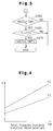
- Fig. 4 illustrates the relationship between the lower threshold value T1 and the total traveled distance of the vehicle 50.
- the lower threshold value T1 is proportional to the total traveled distance of the vehicle 50. This is because the temperature at which the catalytic converters 20, 22 are activated increases as the total traveled distance of the vehicle 50 increases, that is, as the total usage time of the catalytic converters 20, 22 and thus deterioration of the catalytic converters 20, 22 increases. Thus, the catalytic converters 20, 22 must be heated to a higher temperature to obtain the desired purification capability.
- the relationship between the lower threshold value T1 and the total traveled distance is obtained experimentally and stored in the memory 41 of the ECU 40 as data for calculating the lower threshold value T1.
- the ECU 40 determines that the temperature of the catalytic converters 20, 22 will decrease when the vehicle 50 starts moving and thus cause a significant decrease in the purification capability of the catalytic converters 20, 22. In this case, the ECU 40 proceeds to step 140 and sets the stoichiometric flag XACSJ to ON.
- the ECU 40 determines that the temperature of the catalytic converters 20, 22 will not decrease to a value that cannot be ignored when the vehicle 50 starts moving and proceeds to step 150 of Fig. 3. In this case, the stoichiometric flag XACSJ is not set at ON and the combustion mode is not forcibly switched.
- the ECU 40 determines whether the stoichiometric flag XACSJ is ON in step 150. If the flag XACSJ is ON in step 150, the ECU 40 proceeds to step 160 and compares the catalyst temperature Tc with an upper threshold value T2.
- the upper threshold value T2 is used to determine whether the catalytic converters 20, 22 have the desired purification capability from the temperature of the catalytic converters 20, 22 (catalyst temperature Tc) and set at a temperature that is higher than the lower threshold value (T2>T1).
- the upper threshold value T2 is set in accordance with the total traveled distance of the vehicle 50. That is, as shown in Fig. 4, the upper threshold value T2 increases as the total traveled distance of the vehicle 50 increases. This is because, like the relationship between the lower threshold value T1 and the total traveled distance of the vehicle 50, the desired purification capability of the catalytic converters 20, 22 cannot be obtained unless the catalytic converters 20, 22 are heated to a higher temperature as the total traveled distance and thus deterioration of the catalytic converters 20, 22 increases.
- the relationship between the upper threshold value T2 and the total traveled distance is obtained experimentally and stored in the memory 41 of the ECU 40 as data for calculating the upper threshold value T2.
- the ECU 40 determines that the desired purification capability is obtained by the catalytic converters 20, 22 and temperature increase does not have to be enhanced by switching the combustion mode. The ECU 40 thus proceeds to step 170 and sets the stoichiometric flag XACSJ to OFF. The routine is temporarily terminated if the flag XACSJ has been set to off in step 170, if the flag XACSJ is not set at ON in step 150, or if the catalyst temperature Tc is less than or equal to the upper threshold value T2 in step 160.
- the procedures for switching the combustion mode in accordance with the stoichiometric flag XACSJ will now be discussed with reference to the flowchart of Fig. 5.
- the ECU 40 executes the routine shown in the flowchart using interrupts and in predetermined cycles based on the crank angle.
- step 210 the ECU 40 first determines whether or not the full closure signal LL is OFF, that is, whether the acceleration pedal has been depressed to start moving the vehicle 50. If it is determined that the full closure signal LL is OFF in step 210, the ECU 40 proceeds to step 220 and determines whether or not the stoichiometric flag XACSJ is ON.
- step 220 If the ECU 40 determines that the stoichiometric flag XACSJ is ON in step 220, the temperature of the catalytic converters 20, 22 will decrease to a value at which the desired purification capability cannot be obtained when the vehicle 50 starts to move. The ECU 40 thus proceeds to step 230 and forcibly sets the combustion mode to stoichiometric combustion.
- step 210 If the full closure signal LL is ON in step 210 or if the stoichiometric flag XACSJ is OFF in step 220, the ECU 40 proceeds to step 240 and sets the combustion mode in accordance with the operating state of the engine 10.
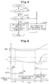
- Fig. 6 is a timing chart showing one example of how the combustion mode is switched in accordance with the temperature increase enhancement routine.
- the combustion mode is switched from stratified charge combustion to stoichiometric combustion (time t4).
- the temperature of the exhaust gas increases when the combustion mode is switched from stratified charge combustion to stoichiometric combustion.
- the increase in the temperature of the catalytic converters 20, 22 (catalyst temperature Tc) is expedited (time t4 to t5) and maintained at a higher temperature in comparison to when stratified charge combustion is continued (as shown by the broken line representing the catalyst temperature Tc).
- the purification capability of the catalytic converters 20, 22 remains satisfactory even immediately after the vehicle 50 starts running.
- the three way catalytic converter 20 especially hinders emission of unburned components (HC and CO) resulting from temperature decrease when the vehicle 50 starts to move.
- the desired purifying capability of the three way catalytic converter 20 and the NOx catalytic converter 22 cannot be obtained if the temperature of the catalytic converters 20, 22 is lower than the catalyst activating temperature.
- the desired purifying capability of, especially, the NOx catalytic converter 22 decreases when the temperature decreases due to the reasons described below.
- the NOx catalytic converter 22 temporarily stores the NOx included in the exhaust gas when stratified charge combustion is performed.
- the maximum value of the storage amount (hereafter referred to as maximum storage amount) is not constant and changes in accordance with the temperature of the catalytic converter 22 (catalyst temperature Tc) as shown in Fig. 7.
- the NOx maximum storage amount is QMAX2. If the catalyst temperature Tc decreases to Tc1, the maximum NOx storage amount Q2 decreases to QMAX1. If the required storage amount is Q2, it is lower than the maximum storage amount QMAX2 when the catalyst temperature is Tc2 but higher than the maximum storage amount QMAX1 when the catalyst temperature is Tc1.
- the excessive amount at temperature Tc1 (Q2-QMAX1) is not stored by the NOx catalytic converter 22 and is emitted from the NOx catalytic converter without being reduced. In such state, the purification capability of the catalytic converter 22 is decreased.
- the exhaust gas purification apparatus of the second embodiment forcibly switches the combustion mode to rich combustion when the vehicle 50 starts moving, at which time the catalyst temperature Tc decreases rapidly. This reduces the NOx stored by the NOx catalytic converter 22 before emission.
- a flag (rich combustion flag XRICHS) for determining whether or not to switch the combustion mode is set based on the temperature of the NOx catalytic converter 22. If the rich combustion flag XRICHS is ON when the vehicle 50 starts to move, the combustion mode is forcibly switched to rich combustion.
- Figs. 8 and 9 are flowcharts show the procedures for setting the rich combustion flag XRICHS.
- the ECU 40 executes the routine shown in the flowcharts using interrupts and in predetermined cycles based on the crank angle.
- the ECU 40 When entering the routine, at step 300, the ECU 40 first estimates the catalyst temperature Tc in the same manner as step 100 of Fig. 2.
- step 310 determines whether or not the rich combustion flag XRICHS is OFF. If the flag XRICHS is ON, the ECU 40 proceeds to step 350, which is shown in Fig. 9.
- step 310 the ECU 40 proceeds to step 320 and determines whether or not the full closure signal LL is ON and the vehicle speed SPD is lower than a predetermined speed ⁇ . In other words, the ECU 40 determines whether the vehicle 50 is not moving in the same manner as step 120 of Fig. 2.
- step 320 If the vehicle 50 is moving in step 320, the ECU 40 proceeds to step 350 of Fig. 9. If the vehicle is not moving in step 320, the ECU 40 proceeds to step 330 and compares the catalyst temperature Tc with a predetermined threshold value T0.
- the threshold value T0 which is compared with the temperature of the NOx catalytic converter 22 when the vehicle 50 is not moving, is used to determine whether the temperature of the NOx catalytic converter 22 (catalyst temperature Tc) will decrease to a value at which the decrease in the maximum storage amount cannot be ignored when the vehicle 50 starts to move.
- step 330 If the ECU 40 determines that the catalyst temperature Tc is lower than the threshold value T0 in step 330, the NOx catalytic converter 22 will decrease when the vehicle 50 starts to move. This significantly decreases the maximum storage amount to a level that cannot be ignored. Therefore, in this case, the ECU 40 proceeds to step 340 and sets the rich combustion flag XRICHS to ON.
- the ECU 40 determines that the maximum storage amount of the NOx will not decrease significantly even if the temperature of the NOx catalytic converter 22 decreases when the vehicle 50 starts to move and proceeds to step 350 of Fig. 9. In this case, the rich combustion flag XRICHS is not set at ON and the combustion mode is thus not forcibly switched.
- the ECU 40 determines whether the rich combustion flag XRICHS has been set to ON through steps 300 to 340. If the rich combustion flag XRICHS is ON, the ECU 40 proceeds to step 360 and determines whether or not a NOx counter value CNOX is set at zero.
- the NOx counter value CNOX indicates the amount of actual storage in the NOx catalytic converter 22. Further the counter value CNOX is increased and decreased separately from this routine in accordance with the engine operating state, such as the engine load and the engine speed.
- the NOx counter value CNOX is increased by a predetermined value in an incremental manner.
- the predetermined value is set in accordance with the engine operating state. Since the amount of HC and CO in the exhaust gas increases when rich combustion is performed and the amount of NOx in the NOx catalytic converter 22 is reduced using the HC and CO as a reduction agents, the NOx counter value CNOX is decreased by a predetermined value, which is set in accordance with the engine operating state, in an decremental manner.
- the actual amount of NOx in the NOx catalytic converter 22 decreases as the NOx counter value CNOX decreases. For example, if the NOx counter value CNOX is set at zero, all of the NOx is reduced in the NOx catalytic converter 22.
- step 360 If the NOx counter value CNOX is zero in step 360, there is no NOx in the NOx catalytic converter 22 and the combustion mode does not have to be switched to reduce the NOx. Thus, the ECU 40 proceeds to step 370 and sets the rich combustion flag XRICHS to OFF. The routine is temporarily terminated if the rich combustion flag XRICHS has been set to OFF in step 370, if the rich combustion flag XRICHS is not set at ON in step 350, or if the NOx counter value CNOX is not zero in step 360.
- the procedures for switching the combustion mode in accordance with the rich combustion flag XRICHS will now be discussed with reference to the flowchart of Fig. 10.
- the ECU 40 executes the routine shown in the flowchart using interrupts and in predetermined cycles based on the crank angle.
- step 410 the ECU 40 first determines whether or not the full closure signal LL is OFF, that is, whether the acceleration pedal has been depressed to start moving the vehicle 50. If it is determined that the full closure signal LL is OFF in step 410, the ECU 40 proceeds to step 420 and determines whether or not the rich combustion flag XRICHS is ON.
- step 420 If the ECU 40 determines that the rich combustion mode XRICHS is OFF in step 420, the temperature of the NOx catalytic converter 22 will decrease to a value at which the maximum storage amount decreases significantly when the vehicle 50 starts to move. The ECU 40 thus proceeds to step 430 and forcibly sets the combustion mode to rich combustion.
- step 410 If the full closure signal LL is ON in step 410 or if the rich combustion flag XRICHS is OFF in step 420, forcible switching of the combustion mode is not performed.
- the ECU 40 thus proceeds to step 440 and sets the combustion mode in accordance with the operating state of the engine 10, such as the engine load and the engine speed. After the combustion mode is set in step 430 or 440, the routine is temporarily terminated.
- Fig. 11 is a timing chart showing one example of how the combustion mode is switched in accordance with the NOx reduction routine.
- the combustion mode is switched from stratified charge combustion to rich combustion (time t4).
- the amount of HC and CO included in the exhaust gas increases when the combustion mode is switched from stratified charge combustion to rich combustion. These unburned components are supplied to the NOx catalytic converter 22 as a reduction agent. Thus, the amount of NOx discharged from the catalytic converter 22 increases. As a result, the actual NOx amount (NOx counter value CNOX) in the NOx catalytic converter 22 decreases significantly in comparison to when stratified charge combustion is continued (as shown by the broken lines representing the catalyst temperature Tc, the maximum storage amount of the NOx catalytic converter 22, and the NOx counter value CNOX). As a result, non-reduced NOx is not emitted from the NOx catalytic converter 22 even if the catalyst temperature Tc decreases immediately after the vehicle 50 starts to move.
- the switching of the combustion mode decreases the amount of NOx in the NOx catalytic converter 22.
- the rich combustion flag XRICHS is set to OFF. This returns the combustion mode to the mode corresponding to the operating state of the engine 10 (stratified charge combustion) from rich combustion (time t5).
- the combustion mode is switched during the period from when the vehicle 50 starts to move subsequent to the catalyst temperature Tc falling below the lower threshold value T1 to when the catalyst temperature Tc reaches the upper threshold value T2. Accordingly, the period during which stoichiometric combustion is performed, that is, the period during which the combustion mode switch enhances the temperature increase of the catalytic converters 20,22 (time t4 to t5), is determined by the threshold values T1, T2.
- the threshold values T1, T2 are set in accordance with the deterioration of the catalytic converters 20, 22. Thus, deterioration of the catalytic converters 20, 22 is considered when setting the temperature increase period.
- the exhaust gas purifying apparatus of the second embodiment has the advantages described below.
- the combustion mode may be switched to other modes, such as lean homogeneous charge combustion or rich combustion, a combustion mode in which the stratification strength is weaker than that of stratified charge combustion (semi-stratified charge combustion), or a combustion mode in which the exhaust temperature is higher than that of stratified charge combustion.
- the combustion mode may be switched to one of lean homogeneous charge combustion, rich combustion, and semi-stratified charge combustion.
- the temperature increase of the catalytic converters 20, 22 may be enhanced by, for example, retarding the ignition timing of the spark plug 16.
- the fuel injection timing may be advanced from the latter half of the compression stroke or part of the fuel may be injected during the suction stroke in addition to the compression stroke.
- the combustion mode may always be switched from stratified charge combustion to stoichiometric combustion for a predetermined period when the vehicle 50 starts to move.
- the threshold values T1, T2 may be set in a variable manner in accordance with a parameter other than the total traveled distance of the vehicle 50 (e.g., the total operational time of the engine 10).
- the threshold values T1, T2 may be fixed values.
- the combustion mode may be switched, for example, under the condition that the NOx storage amount is equal to or greater than a predetermined amount (the NOx counter value CNOX being equal to or greater than a predetermined value) when the vehicle 50 is not moving.
- the combustion mode may be switched under the condition that the difference between the maximum storage amount of the NOx catalytic converter 22, which is obtained from the catalyst temperature Tc, and the actual storage amount is equal to or less than a predetermined amount when the vehicle 50 is not moving.
- the combustion mode may always be switched to rich combustion for a predetermined period when the vehicle 50 starts to move without setting such conditions.
- the period during which the combustion mode is switched to rich combustion may be set, for example, in accordance with the catalyst temperature Tc.
- the HC produced when heating the fuel in the fuel tank may be supplied to the portion of the exhaust passage 18 upstream from the NOx catalytic converter 22.
- the temperature increase of both catalytic converters 20, 22 may be enhanced by performing stoichiometric combustion for a predetermined time period after rich combustion if the decrease of the catalyst temperature Tc is large when the vehicle 50 is not moving. This maintains the capability for eliminating HC from the exhaust gas with the three way catalytic converter 20 and the capability of storing the NOx with the NOx catalytic converter 22 at satisfactory levels.
- an exhaust gas temperature sensor may be arranged in the exhaust passage 18 to detect the temperature of the exhaust gas in the exhaust passage 18 and estimate the catalyst temperature Tc.
- the exhaust gas purifying apparatus according to the present invention may be applied to an engine that performs lean homogeneous charge combustion or semi-stratified charge combustion.
- the exhaust gas purifying apparatus according to the present invention may be applied to an engine which injects fuel into an intake port.
- An exhaust gas purifying apparatus for vehicles having engines that perform lean combustion and purify exhaust gas with a catalytic converter (20) located in an exhaust passage includes a determining means (40) to determine whether the vehicle is moving and a temperature increasing means (40) that increases a temperature of the catalytic converter when the vehicle begins to move.
- the temperature increasing means increases the temperature of the catalytic converter by switching the combustion mode of the engine from lean combustion to stoichiometric combustion.
Landscapes
- Engineering & Computer Science (AREA)
- Chemical & Material Sciences (AREA)
- Combustion & Propulsion (AREA)
- Mechanical Engineering (AREA)
- General Engineering & Computer Science (AREA)
- Chemical Kinetics & Catalysis (AREA)
- Environmental & Geological Engineering (AREA)
- Biomedical Technology (AREA)
- Health & Medical Sciences (AREA)
- Analytical Chemistry (AREA)
- General Chemical & Material Sciences (AREA)
- Oil, Petroleum & Natural Gas (AREA)
- Exhaust Gas After Treatment (AREA)
- Electrical Control Of Air Or Fuel Supplied To Internal-Combustion Engine (AREA)
- Combined Controls Of Internal Combustion Engines (AREA)
- Exhaust Gas Treatment By Means Of Catalyst (AREA)
Priority Applications (1)
| Application Number | Priority Date | Filing Date | Title |
|---|---|---|---|
| EP03021300A EP1380731B1 (de) | 1999-09-03 | 2000-08-31 | Verfahren und Vorrichtung zum Reinigen von Abgasen von Kraftfahrzeugmotoren |
Applications Claiming Priority (2)
| Application Number | Priority Date | Filing Date | Title |
|---|---|---|---|
| JP24997199 | 1999-09-03 | ||
| JP24997199A JP3584798B2 (ja) | 1999-09-03 | 1999-09-03 | 車載用内燃機関の排気浄化装置 |
Related Child Applications (2)
| Application Number | Title | Priority Date | Filing Date |
|---|---|---|---|
| EP03021300A Division EP1380731B1 (de) | 1999-09-03 | 2000-08-31 | Verfahren und Vorrichtung zum Reinigen von Abgasen von Kraftfahrzeugmotoren |
| EP03021300.3 Division-Into | 2003-09-19 |
Publications (3)
| Publication Number | Publication Date |
|---|---|
| EP1081360A2 true EP1081360A2 (de) | 2001-03-07 |
| EP1081360A3 EP1081360A3 (de) | 2003-09-10 |
| EP1081360B1 EP1081360B1 (de) | 2005-03-23 |
Family
ID=17200922
Family Applications (2)
| Application Number | Title | Priority Date | Filing Date |
|---|---|---|---|
| EP00118851A Expired - Lifetime EP1081360B1 (de) | 1999-09-03 | 2000-08-31 | Verfahren und Vorrichtung zum Reinigen von Abgasen von Kraftfahrzeugmotoren |
| EP03021300A Expired - Lifetime EP1380731B1 (de) | 1999-09-03 | 2000-08-31 | Verfahren und Vorrichtung zum Reinigen von Abgasen von Kraftfahrzeugmotoren |
Family Applications After (1)
| Application Number | Title | Priority Date | Filing Date |
|---|---|---|---|
| EP03021300A Expired - Lifetime EP1380731B1 (de) | 1999-09-03 | 2000-08-31 | Verfahren und Vorrichtung zum Reinigen von Abgasen von Kraftfahrzeugmotoren |
Country Status (3)
| Country | Link |
|---|---|
| EP (2) | EP1081360B1 (de) |
| JP (1) | JP3584798B2 (de) |
| DE (2) | DE60018863T2 (de) |
Cited By (5)
| Publication number | Priority date | Publication date | Assignee | Title |
|---|---|---|---|---|
| EP1256704A3 (de) * | 2001-05-11 | 2006-01-04 | Nissan Motor Co., Ltd. | System und Verfahren zur Abgasreinigung für eine Brennkraftmaschine |
| EP1329623A3 (de) * | 2002-01-18 | 2006-06-21 | Hitachi Ltd. | Verfahren und Vorrichtung zur Regelung einer Brennkraftmaschine |
| GB2454346B (en) * | 2007-10-31 | 2012-05-30 | Ford Global Tech Llc | A method for reducing fuel usage |
| US8307638B2 (en) | 2007-03-16 | 2012-11-13 | Toyota Jidosha Kabushiki Kaisha | Exhaust gas purification system for internal combustion engine |
| WO2017088960A1 (de) * | 2015-11-28 | 2017-06-01 | Daimler Ag | Verfahren zum betreiben einer verbrennungskraftmaschine, insbesondere eines kraftwagens |
Families Citing this family (4)
| Publication number | Priority date | Publication date | Assignee | Title |
|---|---|---|---|---|
| JP4510319B2 (ja) * | 2001-04-19 | 2010-07-21 | 本田技研工業株式会社 | 内燃機関の空燃比制御装置 |
| EP1662102B1 (de) * | 2004-11-23 | 2007-06-27 | Ford Global Technologies, LLC | Verfahren und Vorrichtung zur NOx-Umsetzung |
| JP4525640B2 (ja) * | 2006-06-28 | 2010-08-18 | トヨタ自動車株式会社 | 内燃機関の制御装置 |
| JP6408920B2 (ja) * | 2015-01-21 | 2018-10-17 | 本田技研工業株式会社 | 内燃機関の排気浄化システム |
-
1999
- 1999-09-03 JP JP24997199A patent/JP3584798B2/ja not_active Expired - Lifetime
-
2000
- 2000-08-31 DE DE60018863T patent/DE60018863T2/de not_active Expired - Lifetime
- 2000-08-31 EP EP00118851A patent/EP1081360B1/de not_active Expired - Lifetime
- 2000-08-31 EP EP03021300A patent/EP1380731B1/de not_active Expired - Lifetime
- 2000-08-31 DE DE60018487T patent/DE60018487T2/de not_active Expired - Lifetime
Non-Patent Citations (1)
| Title |
|---|
| No relevant documents disclosed * |
Cited By (6)
| Publication number | Priority date | Publication date | Assignee | Title |
|---|---|---|---|---|
| EP1256704A3 (de) * | 2001-05-11 | 2006-01-04 | Nissan Motor Co., Ltd. | System und Verfahren zur Abgasreinigung für eine Brennkraftmaschine |
| EP1329623A3 (de) * | 2002-01-18 | 2006-06-21 | Hitachi Ltd. | Verfahren und Vorrichtung zur Regelung einer Brennkraftmaschine |
| US8307638B2 (en) | 2007-03-16 | 2012-11-13 | Toyota Jidosha Kabushiki Kaisha | Exhaust gas purification system for internal combustion engine |
| GB2454346B (en) * | 2007-10-31 | 2012-05-30 | Ford Global Tech Llc | A method for reducing fuel usage |
| WO2017088960A1 (de) * | 2015-11-28 | 2017-06-01 | Daimler Ag | Verfahren zum betreiben einer verbrennungskraftmaschine, insbesondere eines kraftwagens |
| CN108368793A (zh) * | 2015-11-28 | 2018-08-03 | 戴姆勒股份公司 | 用于运行特别是汽车的内燃机的方法 |
Also Published As
| Publication number | Publication date |
|---|---|
| DE60018863T2 (de) | 2006-05-11 |
| DE60018863D1 (de) | 2005-04-28 |
| JP2001073749A (ja) | 2001-03-21 |
| DE60018487D1 (de) | 2005-04-07 |
| DE60018487T2 (de) | 2006-01-12 |
| EP1081360A3 (de) | 2003-09-10 |
| EP1081360B1 (de) | 2005-03-23 |
| EP1380731B1 (de) | 2005-03-02 |
| JP3584798B2 (ja) | 2004-11-04 |
| EP1380731A3 (de) | 2004-01-21 |
| EP1380731A2 (de) | 2004-01-14 |
Similar Documents
| Publication | Publication Date | Title |
|---|---|---|
| US6311482B1 (en) | Air-fuel ratio control apparatus for internal combustion engines | |
| US6340014B1 (en) | Control for direct fuel injection spark ignition internal combustion engine | |
| US6173571B1 (en) | Exhaust purifying apparatus for an in-cylinder injection type internal combustion engine | |
| US10364716B2 (en) | Exhaust gas control apparatus for internal combustion engine and exhaust gas control method for internal combustion engine | |
| US6438943B1 (en) | In-cylinder injection type internal combustion engine | |
| US6357224B1 (en) | Engine exhaust gas purifying apparatus | |
| US8429902B2 (en) | Secondary air supply system and secondary air supplying method of internal combustion engine | |
| EP1065351B1 (de) | Abgasreinigungsvorrichtung einer Brennkraftmaschine | |
| US6932069B2 (en) | Air fuel ratio control apparatus for an internal combustion engine | |
| JP4918911B2 (ja) | 筒内直接燃料噴射式火花点火エンジンの燃圧制御装置 | |
| US6907862B2 (en) | Combustion control apparatus for internal combustion engine | |
| US6698185B2 (en) | Exhaust gas purification apparatus and process for internal combustion engine | |
| EP1081360B1 (de) | Verfahren und Vorrichtung zum Reinigen von Abgasen von Kraftfahrzeugmotoren | |
| JP2003522893A (ja) | Nox貯蔵触媒の再生の必要性を決定するための装置及び方法 | |
| JP3988518B2 (ja) | 内燃機関の排ガス浄化装置 | |
| JP4244824B2 (ja) | 内燃機関の燃料噴射制御装置 | |
| US20010054284A1 (en) | Emission control method and apparatus of an internal combustion engine | |
| US6408816B1 (en) | Control apparatus and method for direct-injection spark-ignition internal combustion engine | |
| JP2007077913A (ja) | 内燃機関の燃料噴射制御装置 | |
| JP4134395B2 (ja) | 筒内噴射型内燃機関 | |
| EP1083323A2 (de) | Abgasreinigungsanlage für eine Brennkraftmaschine | |
| JP4134398B2 (ja) | 内燃機関 | |
| JP2000080914A (ja) | 内燃機関 | |
| US10968798B2 (en) | Method and system of controlling oxygen purge of three-way catalyst | |
| EP1279817A2 (de) | Steuereinrichtung und Steuerverfahren für eine Brennkraftmaschine |
Legal Events
| Date | Code | Title | Description |
|---|---|---|---|
| PUAI | Public reference made under article 153(3) epc to a published international application that has entered the european phase |
Free format text: ORIGINAL CODE: 0009012 |
|
| 17P | Request for examination filed |
Effective date: 20000831 |
|
| AK | Designated contracting states |
Kind code of ref document: A2 Designated state(s): AT BE CH CY DE DK ES FI FR GB GR IE IT LI LU MC NL PT SE |
|
| AX | Request for extension of the european patent |
Free format text: AL;LT;LV;MK;RO;SI |
|
| PUAL | Search report despatched |
Free format text: ORIGINAL CODE: 0009013 |
|
| PUAF | Information related to the publication of a search report (a3 document) modified or deleted |
Free format text: ORIGINAL CODE: 0009199SEPU |
|
| PUAL | Search report despatched |
Free format text: ORIGINAL CODE: 0009013 |
|
| PUAF | Information related to the publication of a search report (a3 document) modified or deleted |
Free format text: ORIGINAL CODE: 0009199SEPU |
|
| AK | Designated contracting states |
Kind code of ref document: A3 Designated state(s): AT BE CH CY DE DK ES FI FR GB GR IE IT LI LU MC NL PT SE |
|
| AX | Request for extension of the european patent |
Extension state: AL LT LV MK RO SI |
|
| RIC1 | Information provided on ipc code assigned before grant |
Ipc: 7F 01N 3/10 B Ipc: 7F 01N 3/08 B Ipc: 7F 02D 41/02 A |
|
| D17D | Deferred search report published (deleted) | ||
| AK | Designated contracting states |
Kind code of ref document: A3 Designated state(s): AT BE CH CY DE DK ES FI FR GB GR IE IT LI LU MC NL PT SE |
|
| AX | Request for extension of the european patent |
Extension state: AL LT LV MK RO SI |
|
| D17D | Deferred search report published (deleted) | ||
| PUAL | Search report despatched |
Free format text: ORIGINAL CODE: 0009013 |
|
| AK | Designated contracting states |
Kind code of ref document: A3 Designated state(s): AT BE CH CY DE DK ES FI FR GB GR IE IT LI LU MC NL PT SE |
|
| AX | Request for extension of the european patent |
Extension state: AL LT LV MK RO SI |
|
| 17Q | First examination report despatched |
Effective date: 20040504 |
|
| GRAP | Despatch of communication of intention to grant a patent |
Free format text: ORIGINAL CODE: EPIDOSNIGR1 |
|
| AKX | Designation fees paid |
Designated state(s): DE FR GB |
|
| GRAS | Grant fee paid |
Free format text: ORIGINAL CODE: EPIDOSNIGR3 |
|
| GRAA | (expected) grant |
Free format text: ORIGINAL CODE: 0009210 |
|
| AK | Designated contracting states |
Kind code of ref document: B1 Designated state(s): DE FR GB |
|
| REG | Reference to a national code |
Ref country code: GB Ref legal event code: FG4D |
|
| REG | Reference to a national code |
Ref country code: IE Ref legal event code: FG4D |
|
| REF | Corresponds to: |
Ref document number: 60018863 Country of ref document: DE Date of ref document: 20050428 Kind code of ref document: P |
|
| ET | Fr: translation filed | ||
| PLBE | No opposition filed within time limit |
Free format text: ORIGINAL CODE: 0009261 |
|
| STAA | Information on the status of an ep patent application or granted ep patent |
Free format text: STATUS: NO OPPOSITION FILED WITHIN TIME LIMIT |
|
| 26N | No opposition filed |
Effective date: 20051227 |
|
| REG | Reference to a national code |
Ref country code: GB Ref legal event code: 746 Effective date: 20130520 |
|
| REG | Reference to a national code |
Ref country code: DE Ref legal event code: R084 Ref document number: 60018863 Country of ref document: DE Effective date: 20130522 |
|
| REG | Reference to a national code |
Ref country code: FR Ref legal event code: PLFP Year of fee payment: 17 |
|
| REG | Reference to a national code |
Ref country code: FR Ref legal event code: PLFP Year of fee payment: 18 |
|
| REG | Reference to a national code |
Ref country code: FR Ref legal event code: PLFP Year of fee payment: 19 |
|
| PGFP | Annual fee paid to national office [announced via postgrant information from national office to epo] |
Ref country code: FR Payment date: 20190722 Year of fee payment: 20 Ref country code: DE Payment date: 20190820 Year of fee payment: 20 |
|
| PGFP | Annual fee paid to national office [announced via postgrant information from national office to epo] |
Ref country code: GB Payment date: 20190830 Year of fee payment: 20 |
|
| REG | Reference to a national code |
Ref country code: DE Ref legal event code: R071 Ref document number: 60018863 Country of ref document: DE |
|
| REG | Reference to a national code |
Ref country code: GB Ref legal event code: PE20 Expiry date: 20200830 |
|
| PG25 | Lapsed in a contracting state [announced via postgrant information from national office to epo] |
Ref country code: GB Free format text: LAPSE BECAUSE OF EXPIRATION OF PROTECTION Effective date: 20200830 |