EP1081299A1 - Méthode de service pour un appareil sanitaire vidangeable à l'eau, dispositif de contrôle d'une méthode de service et dispositif pour maintenir le niveau d'eau dans un siphon - Google Patents
Méthode de service pour un appareil sanitaire vidangeable à l'eau, dispositif de contrôle d'une méthode de service et dispositif pour maintenir le niveau d'eau dans un siphon Download PDFInfo
- Publication number
- EP1081299A1 EP1081299A1 EP00118812A EP00118812A EP1081299A1 EP 1081299 A1 EP1081299 A1 EP 1081299A1 EP 00118812 A EP00118812 A EP 00118812A EP 00118812 A EP00118812 A EP 00118812A EP 1081299 A1 EP1081299 A1 EP 1081299A1
- Authority
- EP
- European Patent Office
- Prior art keywords
- rinsing
- sequences
- service
- control unit
- sequence
- Prior art date
- Legal status (The legal status is an assumption and is not a legal conclusion. Google has not performed a legal analysis and makes no representation as to the accuracy of the status listed.)
- Withdrawn
Links
Images


Classifications
-
- E—FIXED CONSTRUCTIONS
- E03—WATER SUPPLY; SEWERAGE
- E03D—WATER-CLOSETS OR URINALS WITH FLUSHING DEVICES; FLUSHING VALVES THEREFOR
- E03D9/00—Sanitary or other accessories for lavatories ; Devices for cleaning or disinfecting the toilet room or the toilet bowl; Devices for eliminating smells
- E03D9/002—Automatic cleaning devices
-
- E—FIXED CONSTRUCTIONS
- E03—WATER SUPPLY; SEWERAGE
- E03D—WATER-CLOSETS OR URINALS WITH FLUSHING DEVICES; FLUSHING VALVES THEREFOR
- E03D5/00—Special constructions of flushing devices, e.g. closed flushing system
- E03D5/10—Special constructions of flushing devices, e.g. closed flushing system operated electrically, e.g. by a photo-cell; also combined with devices for opening or closing shutters in the bowl outlet and/or with devices for raising/or lowering seat and cover and/or for swiveling the bowl
- E03D5/105—Special constructions of flushing devices, e.g. closed flushing system operated electrically, e.g. by a photo-cell; also combined with devices for opening or closing shutters in the bowl outlet and/or with devices for raising/or lowering seat and cover and/or for swiveling the bowl touchless, e.g. using sensors
Definitions
- the invention relates to a service method for a liquid-flushable sanitary apparatus according to the preamble of claim 1 , a control device for controlling a service method according to the preamble of claim 9 and a device for maintaining an odor block in an odor trap of a sanitary apparatus according to the Preamble of claim 19 .
- Flushing processes in sanitary appliances that can be flushed with liquid have three main objectives: firstly, the one mixed with urine and / or faeces should be in the bowls of the sanitary appliances existing rinsing liquid, generally water, with additional rinsing liquid be swept away; secondly, the formation of deposits from dirt, urine stone and lime in the interior of the bowls and in the piping system connected to the bowls the sanitary appliances should be prevented, and thirdly, missing, for example, evaporated Flushing liquid to be replaced so that the limit level is maintained or is again achieved to ensure an odor barrier in the downstream of the Sanitary appliances arranged odor trap is necessary.
- Simple service procedures are designed so that after each use of the sanitary equipment a rinsing process is in progress. Between these when using the sanitary apparatus Initialized rinses are pauses in rinsing, the duration of which depends on the frequency the use of the sanitary facilities is different. Evaporates during the rinsing breaks part of the water in the bowl. Long rinsing breaks can therefore especially at high ambient temperatures, result in a proportionate large amount of detergent evaporates, with the result that the water level of the liquid in the bowl drops below a limit level at which an odor barrier between the bowl and the sewage system leading away from it consists. In the simplest of these service procedures, the duration of the rinsing processes is constant.
- the duration of the rinsing process is generally set on a device to control the flushing device, for example via a potentiometer or an infrared interface, by rotating a setting member, for example by means of a Screwdriver.
- remote control devices could be used to control the new service procedure are used, for example remote control devices with optical signal transmission such as infrared, also TV or video systems and high-frequency systems such as those used in remote controls for door and car locks come.
- optical signal transmission such as infrared
- TV or video systems TV or video systems
- high-frequency systems such as those used in remote controls for door and car locks come.
- Control devices with Infrared signal transmission requires visual contact and optics that are not vandal-proof can be trained.
- Control devices with high-frequency signal transmission are unfavorable if the receivers are close together, as is the case with Urinals are the case in larger sanitary facilities. So that a receiver does not receive signals is influenced, which are intended for another recipient, a corresponding Coding done; this has the disadvantageous consequence that either for each recipient a separate control device must be provided or that the coding to the respective recipient must be adjusted.
- a first operating unit only serves to control the system switch off and thereby allow manual cleaning of the bowl while which no unintended rinsing takes place; this first control unit is simple in terms of their training and handling.
- a second control unit is used to set the rinsing time, to carry out emptying of the rinsing system when there are upcoming low ambient temperatures and to query the number of performed Douching and diagnosis of malfunctions; has this second control unit the aspect of a remote control and is therefore neither in their training nor easy to use.
- the flushing liquid is introduced into the bowls of sanitary appliances such as urinals not only for the purpose of washing away of rinsing fluid already mixed in the urine but also in the bowl for the purpose of maintaining the odor barrier between the bowl and its Environment on the one hand and the sewer system connected downstream of it on the other hand.
- a conventional so-called odor trap or siphons between the bowl and the sewer system
- the flushing liquid acts as a plug, which prevents air from circulating between prevents the bowl and its surroundings and the sewer system; this Grafting is of course only possible if the water level is correct the rinsing liquid is high enough.
- Another reason for the drop in the water level the rinsing liquid is a suction of rinsing liquid due to a negative pressure in the sewer system, which can occur when flushing adjacent bowls.
- Another cause for the drop in the level of the rinsing liquid is the emergence an overpressure in the room in which the sanitary apparatus is stationed, for example when a door to an adjacent room is opened with higher pressure.
- the level of the rinsing liquid in the odor trap above a Limit level to maintain the mentioned plug effect by the rinsing liquid in the odor trap or siphon.
- the odor barrier not guarantee with the previously known service procedures, namely always when, on the one hand, the level drops below the limit level mentioned and on the other hand, not immediately after this sinking, use of the sanitary apparatus and the subsequent rinsing of the bowl takes place.
- the odor barrier can therefore only be maintained if automatically immediately after the drop the limit water level even when the sanitary apparatus is not in use even a small amount of dishwashing liquid into the bowl and from there into the odor trap or can get into the siphon.
- the duration of a rinsing process is therefore not the rinse time is set, but there are various service sequences preset, from which a service frequency is called up can.
- the service sequences include rinsing sequences that are in the normal state, that is usual use of the sanitary apparatus, run according to the different Ratios of differently initiated and differently running rinsing sequences can be preset. All rinsing sequences consist of rinsing processes that are in intervals and / or after use and / or to comply with the odor barrier guaranteeing level of the rinsing liquid, preferably the Time intervals of the rinses and the amounts of rinsing liquid used in each case can be adjusted.
- Additive processes are provided in which an additive is brought into the bowl; cleaning, disinfecting, decalcifying or fragrance agents or combinations are used as additives such means in question; the automated addition of such additives offers a guarantee for the fact that they are actually used and in the correct dosage.
- maintenance cleaning sequences can be provided, which between two phases of the normal state take place and for periodic thorough cleaning to care.
- the maintenance cleaning sequences can include rinsing breaks, rinsing processes and Additive operations include.
- the maintenance cleaning sequences are also available different variants available; but during rinsing sequences generally carried out the same variant continuously or for a long time is then the preferred option when carrying out any maintenance cleaning or a suitable maintenance cleaning sequence from the preset maintenance cleaning sequences to be selected.
- the service sequences can also include diagnostic sequences with whose Various types of faults can be detected and displayed. Both Disruptions can be wear-related or incorrect manipulations caused or due to lack of energy or lack of flushing fluid act.
- the advantages of the new service procedure are obvious. There are many different Set service sequences so that the service procedure is not just the usual one Rinsing processes but also ensuring the odor barrier and the periodic Maintenance cleaning carried out and additional faults detected and displayed can be.
- the rinsing sequences which are the usual ones Rinses can also correspond to the respective conditions in a simple manner be set; this not only achieves hygiene and smell established conditions but can also the detergent or water consumption minimize in line with prevailing needs.
- the maintenance cleaning sequences enable the additional periodic maintenance cleaning to be carried out flawlessly even if no qualified personnel is available; in particular, additives such as cleaning agents or decalcifying agents can also be added in the required dosage.
- the diagnostic sequences finally, it makes it possible to carry out further maintenance without any problems; Faults or signs of wear are displayed or can be detected early and also by unqualified personnel; you can in the Follow by specialists during a phase of less use of the sanitary facility be remedied before the sanitary facility fails completely due to a major defect; It is particularly advantageous that the specialists are informed of the type of fault can, so that the necessary spare parts and tools without previewing the Damage can be put together and brought.
- the control device for controlling service processes comprises only one control unit per sanitary appliance and a single control unit for a variety of sanitary appliances, recoding does not correspond to the respective control unit necessary is.
- the control unit can be mounted in a vandal-proof manner because of the signal transmission does not take place by infrared and therefore requires no line of sight.
- the control unit is simple in structure and handling.
- the device for maintaining the odor barrier comprises a sensor that is switched on a suitable place downstream of the bowl in the odor trap or Siphons of a sanitary apparatus is installed and that when the water level drops of the detergent below a limit level emits a signal that the washing device prompted to perform a rinse or to dispense a small amount of water, which is enough to restore the odor barrier.
- the sensor can be the same which is also used to initiate use-induced flushing processes. This device is simple to set up, but allows it in an efficient and water-saving manner almost permanent maintenance of the odor barrier.
- SS service sequences SS , namely five rinsing sequences S1, S2, S3, S4, S5, three maintenance cleaning sequences U1, U2, U3 and a diagnostic sequence D1 with five Diagnostic steps d1, d2, d3, d4, d5, which are described in more detail below; the times and amounts of rinsing liquid and the number and type of rinsing processes of the various service sequences are only given as examples and can vary within wide limits.
- the five rinsing sequences S1 to S5 are provided, which are preset.
- one of the rinsing sequences is called up or selected either during assembly by a specialist or later by an operator 1 using an operating unit 10.1 via a control unit of a control device (not shown in FIG. 1) .
- the operating unit 10.1 shown in FIG. 1 has three keys S, U and D.
- One of the preset rinsing sequences S1, S2, S3, S4 or S5 is selected using the S button on the operating unit 10.1
- one of the maintenance cleaning sequences U1 to U3 is selected using the U button on the control unit 10.1 and the diagnostic device is selected.
- Sequence D1 is carried out using key D of the command device 10.1 .
- T means a time
- Tstop means stopping the time
- Treset resetting the time to zero
- START the start of use
- END the end of use
- ODOR STOP the presence of an odor barrier .
- the first rinsing sequence S1 and the second rinsing sequence S2 are particularly suitable for sanitary appliances which are used very frequently for a short time and then no longer for a longer period, for example for schools, cinemas and similar areas, where each during Breaks a frequent use of the sanitary facilities takes place.
- the consumption of rinsing liquid can be greatly reduced in these rinsing sequences S1 and S2 .
- rinsing liquid Small amounts of rinsing liquid are advantageous if little rinsing liquid is available stands or it is very expensive. However, there is a large amount of rinsing liquid available at a negligible price, for example because generally none There is a shortage of water and not drinking water but less or as rinsing liquid if untreated service water is used at all, the use of larger ones can be used Amounts of flushing liquid may be more advantageous, on the one hand because of the hygienic conditions and on the other hand because of the lower concentration of urine in the wastewater, which causes the Bodies of water and possibly also the sewage treatment plants with larger quantities lower intensity.
- additives such as cleaning agents, disinfectants, decalcifying agents or fragrances can be dispensed into the bowl according to FIGS. 2B and 2F , either in a separate step of the service process or at the same time with inflowing rinsing liquid.
- only one diagnostic sequence D1 is provided. It has five diagnosis steps d1, d2, d3, d4, d5 , which run consecutively when the diagnosis sequence D1 is selected .
- diagnosis steps d1, d2, d3, d4, d5 which run consecutively when the diagnosis sequence D1 is selected .
- the operating unit 10.1 can also be designed such that it contains only one or two buttons; perform the multiple functions.
- a design of the operating unit with two keys namely a key S / D for selecting the washing sequences S1 to S5 and for initiating the diagnostic sequences D1 , and a key U for initiating or selecting the maintenance cleaning sequences has proven effective U1 to U3 .
- the S / D key must be pressed briefly for the diagnostic sequence D1 and long for the preselection of the rinsing sequences S1 to S5 .
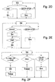
- the flow of the functions would essentially correspond to a flow diagram, not shown, in which the input of the flow diagram of FIG. 2A would be connected to the output of the flow diagram of FIG. 4 .
- control device 10 for carrying out the method, including the possible mounting positions of the control unit 10.2, are described in more detail below.
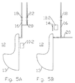
- FIGS. 5A and 5B each show a control unit 10.2 of a control device 10 , which further includes the operating unit 10.1 already shown in FIG. 1 .
- the control device 10 serves to control a service method that is applied to a sanitary apparatus 12 in the form of a urinal with the bowl 13 .
- the control unit 10.2 of the control device 10 comprises a plurality of electronic elements and a mounting box in which these electronic elements are accommodated.
- 5A shows the control unit 10.2 mounted in a first position, namely above the bowl 13 .
- the control unit 10.2 can be arranged behind a wall or behind a wall covering or behind a cover plate 14 in a recess in the wall.
- 5B shows the control unit 10.2 in a second position, namely directly behind the bowl 13 . In this position, the control unit 10.2 is perfectly protected against vandalism, but replacing a defective control unit 10.2 is relatively complex since it can only be carried out when the bowl 13 is removed.
- a detail of the sanitary apparatus 12 is shown below, namely the device for adding an additive such as, for example, a cleaning, disinfecting, decalcifying or scenting agent to the rinsing liquid, which preferably with individual or all rinsing processes of the new one Service procedure can be combined.
- the flushing liquid is supplied to the bowl 13 in the usual way through a flushing liquid supply line 16 in which a solenoid valve 18 is arranged.
- An additive supply line 20 opens into the rinsing liquid supply line 16 , preferably in the region close to the bowl, or, as not shown, into the bowl 13 .
- the additive supply line 20 also contains a controllable valve 22, which is controlled in such a way that a certain amount of the additive gets into the bowl 13 during certain or all rinsing processes or possibly also outside a rinsing process.
- the additive supply line 20 contains no valve; the additive is sucked in by the rinsing liquid from an additive container (not shown) during each rinsing process according to the principle of a water jet pump and thus reaches the region of the rinsing liquid supply line 16 near the bowl.
- the arrangement and design of the control unit on the one hand and the additive adding device on the other hand are independent of one another and not restricted to the design forms shown in FIGS. 5A and 5B .
- control device 10 Conventional control devices of various types can be used to control the new service process.
- the control device 10 according to the invention is particularly suitable, the details of which are shown in FIGS. 6A to 6D and are described below.
- 6A shows the control unit 10.1 and the operating unit 10.2 of the control device 10 , the operating unit 10.1 shown here only having two keys, namely a first, combined S / D key for the rinsing sequences S1 to S4 and the diagnosis sequence D1 and one has second key U for the maintenance cleaning sequences U1 to U3 .
- This control unit 10.1 was designed so that it is easy to operate thanks to the small number of only two buttons S / D and U ; for this purpose it is further advantageous if the keys S / D and U have different colors and / or shapes and / or are labeled with symbols or pictograms.
- Command signals K go from operating unit 10.1 to control unit 10.2 and acknowledgment signals Q go from control unit 10.2 to operating unit 10.1 ; these signals could be electronic, electromagnetic, optical or acoustic; however, devices with optical signals cannot be manufactured to be vandal-proof.
- the operating unit 10.1 can have a display 24 for the optical display of received electronic signals.
- the line representing the command signals K is drawn in FIG. 6A , while the line representing the acknowledgment signals Q is only dashed.
- the control device 10 works in such a way that the pulse-width-modulated electromagnetic waves of the low frequency range are transmitted by means of a ferrite rod by the transmitter, that is to say the operating unit 10.1 , and are received and evaluated on the receiver side, that is to say in the control unit, by means of a further ferrite rod.
- the shape of these directional command signals K is that of a lobe 30 , as shown in FIGS. 6B and 6C .
- the length of this naturally non-material lobe 30 is preferably in the range of approximately one meter and its width is in the range of approximately half a meter.
- the dimensions of the lobe 30 are such that only one control unit 10.2 is addressed with the operating unit 10.1 , as can be seen from FIG. 6C , where the control units 20.2 mounted behind a wall 40 are arranged in a completely vandal-proof manner and yet by the operating unit 10.1 emitted command signals K can be reached individually.
- this single operating unit 10.1 serves not only for the cleaning staff to control the maintenance cleaning sequences U1 to U3 and the diagnosis sequence D1 , but also for the specialists for presetting or programming all service sequences and in particular for selecting the suitable rinsing sequence S1, S2, S3, S4 or S5 .
- control unit 10.2 In order to prevent the selection of the rinsing sequence from being changed accidentally or maliciously, the control unit 10.2 is designed in such a way that it can only be reprogrammed within a certain programming period, for example 30 minutes after the start of the power supply. Although this has the consequence that the power supply must be interrupted before an intended reprogramming, but this means only a minimal disadvantage, since reprogramming is generally not carried out.
- the control unit 10.2 preferably also has a digital interface that is normally not used. This serves to preset or overload service sequences tailored to special needs. Via the same interface, variables determined by the control unit 10.2, such as the number of rinses carried out, can also be transmitted to a computer unit, where they can then be statistically evaluated. For this purpose and also for programming purposes, the control devices 10.2 can also be connected to a bus 26 , as shown in FIG. 6D ; this would have the advantage that several flushes can be carried out at different times despite simultaneous use, for example if the pressure of the flushing liquid and / or the cross section of the flushing liquid supply line is small.
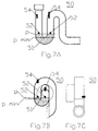
- FIG. 7A, 7B and 7C show an odor trap or siphon 50 , which is arranged downstream of a bowl, not shown, of a sanitary appliance.
- This odor trap or siphon 50 serves to produce an odor barrier between the bowl (not shown) and the room in which it is mounted on the one hand and the sewer system on the other.
- the odor barrier comes about because the odor trap or siphon 50 is completely filled with rinsing liquid in at least one cross section 51 , which to a certain extent forms a plug. So that this plug is retained, the level P of the rinsing liquid must not drop below a limit level P min .
- a sensor 52 or 54 is arranged in the odor trap or siphon 50 , which monitors the level P , determines the drop in the level P below the limit level P min and then emits a signal to cause rinsing liquid in the bowl is refilled.
- the sensor 52 or 54 can be arranged before or after the cross section 51 of the odor barrier. With simple sanitary appliances, forced flushing can be initiated at certain intervals. However, this means an unnecessary consumption of rinsing liquid; in order to maintain or regain the odor barrier, only a minimal amount of rinsing liquid is required.
- Suitable sensors are both media sensors 52 , for example optical sensors, capacitive sensors, inductive sensors, ultrasound sensors, conductivity sensors or mechanical-hydraulic sensors such as floats, and distance sensors 54 , which according to FIG. 3A , 3B and 3C .
- the sensors 52 and 54 which serve to ensure the maintenance of the odor barrier, are preferably the same sensors that also initiate the use-induced rinsing processes.
Landscapes
- Engineering & Computer Science (AREA)
- Health & Medical Sciences (AREA)
- Public Health (AREA)
- Life Sciences & Earth Sciences (AREA)
- Hydrology & Water Resources (AREA)
- Water Supply & Treatment (AREA)
- Aviation & Aerospace Engineering (AREA)
- Epidemiology (AREA)
- Bidet-Like Cleaning Device And Other Flush Toilet Accessories (AREA)
Applications Claiming Priority (2)
| Application Number | Priority Date | Filing Date | Title |
|---|---|---|---|
| CH161799 | 1999-09-06 | ||
| CH161799 | 1999-09-06 |
Publications (1)
| Publication Number | Publication Date |
|---|---|
| EP1081299A1 true EP1081299A1 (fr) | 2001-03-07 |
Family
ID=4214630
Family Applications (1)
| Application Number | Title | Priority Date | Filing Date |
|---|---|---|---|
| EP00118812A Withdrawn EP1081299A1 (fr) | 1999-09-06 | 2000-08-31 | Méthode de service pour un appareil sanitaire vidangeable à l'eau, dispositif de contrôle d'une méthode de service et dispositif pour maintenir le niveau d'eau dans un siphon |
Country Status (1)
| Country | Link |
|---|---|
| EP (1) | EP1081299A1 (fr) |
Cited By (3)
| Publication number | Priority date | Publication date | Assignee | Title |
|---|---|---|---|---|
| EP2011930A2 (fr) * | 2007-07-03 | 2009-01-07 | VIEGA GmbH & Co. KG. | Chasse d'eau avec système de bus de donnés |
| US7814582B2 (en) | 2003-12-31 | 2010-10-19 | Kimberly-Clark Worldwide, Inc. | System and method for measuring and monitoring overflow or wetness conditions in a washroom |
| NL2009825C2 (en) * | 2012-11-16 | 2014-05-21 | Ipee Bvba | Sanitary appliance and method of determining use thereof. |
Citations (7)
| Publication number | Priority date | Publication date | Assignee | Title |
|---|---|---|---|---|
| US4815150A (en) * | 1987-03-17 | 1989-03-28 | Bieri Pumpenbau Ag. | Double-urinal flushing apparatus and method for automatic operation |
| DE3735854A1 (de) * | 1987-10-23 | 1989-05-11 | Philips Patentverwaltung | Anordnung zur steuerung und fernsteuerung eines bei annaeherung bzw. weggang eines benutzers ein- bzw. abschaltbaren, batteriebetriebenen geraetes |
| DE3920581A1 (de) * | 1989-06-23 | 1991-01-24 | Dal Georg Rost & Soehne Gmbh A | Wasserspueleinrichtung mit infrarot-abtastung |
| EP0597286A1 (fr) * | 1992-11-11 | 1994-05-18 | von Lepel, Freifrau, Barbara | Procédé de fonctionnement d'un urinoir pour économiser l'eau de rinçage et urinoir pour appliquer le procédé |
| WO1994016158A1 (fr) * | 1993-01-16 | 1994-07-21 | Sanivac Vakuumtechnik Gmbh | Dispositif de commande du fonctionnement de w.-c. a aspiration |
| DE19608157A1 (de) * | 1996-01-04 | 1997-07-17 | Steinel Ag | Steuervorrichtung für ein Urinal o. dgl. |
| WO1999018296A1 (fr) * | 1997-10-01 | 1999-04-15 | Brand-Gerhart, Rosemarie | Dispositif pour le declenchement automatique d'un processus de chasse dans des urinoirs ou des installations sanitaires similaires |
-
2000
- 2000-08-31 EP EP00118812A patent/EP1081299A1/fr not_active Withdrawn
Patent Citations (7)
| Publication number | Priority date | Publication date | Assignee | Title |
|---|---|---|---|---|
| US4815150A (en) * | 1987-03-17 | 1989-03-28 | Bieri Pumpenbau Ag. | Double-urinal flushing apparatus and method for automatic operation |
| DE3735854A1 (de) * | 1987-10-23 | 1989-05-11 | Philips Patentverwaltung | Anordnung zur steuerung und fernsteuerung eines bei annaeherung bzw. weggang eines benutzers ein- bzw. abschaltbaren, batteriebetriebenen geraetes |
| DE3920581A1 (de) * | 1989-06-23 | 1991-01-24 | Dal Georg Rost & Soehne Gmbh A | Wasserspueleinrichtung mit infrarot-abtastung |
| EP0597286A1 (fr) * | 1992-11-11 | 1994-05-18 | von Lepel, Freifrau, Barbara | Procédé de fonctionnement d'un urinoir pour économiser l'eau de rinçage et urinoir pour appliquer le procédé |
| WO1994016158A1 (fr) * | 1993-01-16 | 1994-07-21 | Sanivac Vakuumtechnik Gmbh | Dispositif de commande du fonctionnement de w.-c. a aspiration |
| DE19608157A1 (de) * | 1996-01-04 | 1997-07-17 | Steinel Ag | Steuervorrichtung für ein Urinal o. dgl. |
| WO1999018296A1 (fr) * | 1997-10-01 | 1999-04-15 | Brand-Gerhart, Rosemarie | Dispositif pour le declenchement automatique d'un processus de chasse dans des urinoirs ou des installations sanitaires similaires |
Cited By (6)
| Publication number | Priority date | Publication date | Assignee | Title |
|---|---|---|---|---|
| US7814582B2 (en) | 2003-12-31 | 2010-10-19 | Kimberly-Clark Worldwide, Inc. | System and method for measuring and monitoring overflow or wetness conditions in a washroom |
| EP2011930A2 (fr) * | 2007-07-03 | 2009-01-07 | VIEGA GmbH & Co. KG. | Chasse d'eau avec système de bus de donnés |
| EP2011930A3 (fr) * | 2007-07-03 | 2009-10-21 | VIEGA GmbH & Co. KG. | Chasse d'eau avec système de bus de donnés |
| NL2009825C2 (en) * | 2012-11-16 | 2014-05-21 | Ipee Bvba | Sanitary appliance and method of determining use thereof. |
| WO2014076284A1 (fr) * | 2012-11-16 | 2014-05-22 | Ipee Bvba | Appareil sanitaire et procédé de détermination de son utilisation |
| US10732010B2 (en) | 2012-11-16 | 2020-08-04 | Ipee Nv | Sanitary appliance and method of determining use thereof |
Similar Documents
| Publication | Publication Date | Title |
|---|---|---|
| DE69736207T2 (de) | Vorrichtung zum Steuern einer Gruppe von Badezimmergeräten | |
| EP1601841B1 (fr) | Procede pour commander l'amenee d'eau a une installation sanitaire | |
| DE10157975B4 (de) | System zur Fernbetätigung einer Personenhygiene- oder Sanitäreinrichtung | |
| WO2009026733A1 (fr) | Procédé et dispositif de détermination des intervalles de maintenance | |
| DE102008047938A1 (de) | Trinkwasserleitungssystem zur Erhaltung der Trinkwassergüte und Verfahren zum Betrieb eines solchen Trinkwasserleitungssystems | |
| DE3008025C2 (fr) | ||
| DE102015106220A1 (de) | Sanitäreinrichtung | |
| EP3456891A1 (fr) | Cuve pour matières fécales pour un dispositif sanitaire | |
| EP2553178A1 (fr) | Dispositif permettant de constater et de définir le moment auquel doit être effectué un remplacement de pièces d'usure d'un appareil sanitaire en fonction de la fréquence d'utilisation | |
| EP1081299A1 (fr) | Méthode de service pour un appareil sanitaire vidangeable à l'eau, dispositif de contrôle d'une méthode de service et dispositif pour maintenir le niveau d'eau dans un siphon | |
| EP2034097A2 (fr) | Réservoir de chasse d'eau intelligent | |
| EP3795762A2 (fr) | Procédé de fonctionnement d'un système d'urinoir, système d'urinoir et système de consommation d'eau doté d'un système d'urinoir | |
| EP3085841A1 (fr) | Dispositif de lavage de parties intimes comprenant un dispositif de stérilisation par rayonnement uv | |
| EP1135559B1 (fr) | Dispositif d'actionnement de chasse d'eau sans contact pour des toilettes | |
| DE10330323B4 (de) | WC-Spülkasten mit Reinigungsmitteleinheit | |
| DE202021004386U1 (de) | Spül- und Vorspülsystem sowie Nachrüstset für eine Sanitäreinrichtung | |
| EP0597286A1 (fr) | Procédé de fonctionnement d'un urinoir pour économiser l'eau de rinçage et urinoir pour appliquer le procédé | |
| DE102011000485B4 (de) | Urinal mit Reinigungsfunktion | |
| EP1339923A1 (fr) | Dispositif de chasse sans contact pour w.-c., et procede d'actionnement sans contact d'une chasse de w.-c. | |
| DE102016009217A1 (de) | Sanitäre Vorrichtung zur Aufnahme von Körperausscheidungen | |
| DE10330334B4 (de) | Toilettensystem | |
| DE102017106557A1 (de) | Hygienestation | |
| DE102007005750B4 (de) | Umbauvorrichtung für eine automatische Toilettenspülung und Luftdeodorierung | |
| EP4105393A1 (fr) | Dispositif de rinçage d'hygiène | |
| EP4317623A1 (fr) | Dispositif de chasse sous pression d'un cuvette de wc, cuvette de wc dotée d'un tel dispositif et son utilisation |
Legal Events
| Date | Code | Title | Description |
|---|---|---|---|
| PUAI | Public reference made under article 153(3) epc to a published international application that has entered the european phase |
Free format text: ORIGINAL CODE: 0009012 |
|
| AK | Designated contracting states |
Kind code of ref document: A1 Designated state(s): AT BE CH CY DE DK ES FI FR GB GR IE IT LI LU MC NL PT SE |
|
| AX | Request for extension of the european patent |
Free format text: AL;LT;LV;MK;RO;SI |
|
| 17P | Request for examination filed |
Effective date: 20010705 |
|
| AKX | Designation fees paid |
Free format text: AT BE CH CY DE DK ES FI FR GB GR IE IT LI LU MC NL PT SE |
|
| 17Q | First examination report despatched |
Effective date: 20020409 |
|
| STAA | Information on the status of an ep patent application or granted ep patent |
Free format text: STATUS: THE APPLICATION HAS BEEN WITHDRAWN |
|
| 18W | Application withdrawn |
Withdrawal date: 20020829 |