EP1081029A1 - Procedure for blind-assembly of at least one component and device foor carrying out the procedure - Google Patents
Procedure for blind-assembly of at least one component and device foor carrying out the procedure Download PDFInfo
- Publication number
- EP1081029A1 EP1081029A1 EP00402356A EP00402356A EP1081029A1 EP 1081029 A1 EP1081029 A1 EP 1081029A1 EP 00402356 A EP00402356 A EP 00402356A EP 00402356 A EP00402356 A EP 00402356A EP 1081029 A1 EP1081029 A1 EP 1081029A1
- Authority
- EP
- European Patent Office
- Prior art keywords
- door
- component
- wall
- mounting
- cassette
- Prior art date
- Legal status (The legal status is an assumption and is not a legal conclusion. Google has not performed a legal analysis and makes no representation as to the accuracy of the status listed.)
- Granted
Links
Images


Classifications
-
- B—PERFORMING OPERATIONS; TRANSPORTING
- B62—LAND VEHICLES FOR TRAVELLING OTHERWISE THAN ON RAILS
- B62D—MOTOR VEHICLES; TRAILERS
- B62D65/00—Designing, manufacturing, e.g. assembling, facilitating disassembly, or structurally modifying motor vehicles or trailers, not otherwise provided for
-
- Y—GENERAL TAGGING OF NEW TECHNOLOGICAL DEVELOPMENTS; GENERAL TAGGING OF CROSS-SECTIONAL TECHNOLOGIES SPANNING OVER SEVERAL SECTIONS OF THE IPC; TECHNICAL SUBJECTS COVERED BY FORMER USPC CROSS-REFERENCE ART COLLECTIONS [XRACs] AND DIGESTS
- Y10—TECHNICAL SUBJECTS COVERED BY FORMER USPC
- Y10T—TECHNICAL SUBJECTS COVERED BY FORMER US CLASSIFICATION
- Y10T29/00—Metal working
- Y10T29/49—Method of mechanical manufacture
- Y10T29/49826—Assembling or joining
- Y10T29/49895—Associating parts by use of aligning means [e.g., use of a drift pin or a "fixture"]
-
- Y—GENERAL TAGGING OF NEW TECHNOLOGICAL DEVELOPMENTS; GENERAL TAGGING OF CROSS-SECTIONAL TECHNOLOGIES SPANNING OVER SEVERAL SECTIONS OF THE IPC; TECHNICAL SUBJECTS COVERED BY FORMER USPC CROSS-REFERENCE ART COLLECTIONS [XRACs] AND DIGESTS
- Y10—TECHNICAL SUBJECTS COVERED BY FORMER USPC
- Y10T—TECHNICAL SUBJECTS COVERED BY FORMER US CLASSIFICATION
- Y10T29/00—Metal working
- Y10T29/49—Method of mechanical manufacture
- Y10T29/49826—Assembling or joining
- Y10T29/49904—Assembling a subassembly, then assembling with a second subassembly
-
- Y—GENERAL TAGGING OF NEW TECHNOLOGICAL DEVELOPMENTS; GENERAL TAGGING OF CROSS-SECTIONAL TECHNOLOGIES SPANNING OVER SEVERAL SECTIONS OF THE IPC; TECHNICAL SUBJECTS COVERED BY FORMER USPC CROSS-REFERENCE ART COLLECTIONS [XRACs] AND DIGESTS
- Y10—TECHNICAL SUBJECTS COVERED BY FORMER USPC
- Y10T—TECHNICAL SUBJECTS COVERED BY FORMER US CLASSIFICATION
- Y10T29/00—Metal working
- Y10T29/53—Means to assemble or disassemble
- Y10T29/53978—Means to assemble or disassemble including means to relatively position plural work parts
Definitions
- the present invention relates to a blind mounting method at least one component and one device for implementing this method.
- the blind assembly of components is a problem for especially automobile manufacturers.
- This method and this device are especially used when assembling a multi-function plate in a opening element for vehicle.
- the opening element may be a door or a vehicle tailgate.
- the primary object of the present invention is therefore to overcome the disadvantages of the prior art by proposing a method allowing the blind positioning and mounting of components.
- the housing is integral with a second wall.
- the second wall forms with the first a volume.
- the complementary components are a covering component and an operating component.
- the volume is a vehicle opening.
- the three-dimensional connection is rigid in X and Z and stiffenable in Y by a key.
- the multifunctional plate is a vehicle door cassette.
- an opening element is a door or a tailgate
- the step of removing stiffening frees the space between the two walls forming a well for a mobile element such as a window, one of the components to be mounted is the technical part of an order exterior opening.
- the method comprises a step of mounting of an external part of the door opening control comprising an operating member and / or a covering outside the door, assembly being carried out by fixing on the opening control outer to enclose the wall between the outer part and the technical part of the external opening control.
- a removable connection means comprises a bar comprising means allowing its locking on the one hand on the second wall, and on the other hand on one of the components intended to be mounted at inside the volume, these locking means being unlockable once the component put in place and fixed in the volume in order to free the space between the two walls of the volume.
- the step of mounting and joining together the assembly formed by the cassette and all the interior elements inside of a vehicle door consists, firstly, in securing each element to the walls of the door, and on the other hand to be joined, when this is required, at least one mechanism of each element to a mechanism of the cassette.
- a second object of the invention is to propose a device allowing the implementation of the method according to the invention.
- the device for mounting at least at least one component inside a vehicle opening element comprises means for removable connection of the component (s) to a cassette intended to be mounted on the opening element, the removable connection means being shaped to ensure rotation and translation locking by relation to the cassette of the component or components to be mounted inside the element opening.
- a removable connection means comprises a bar comprising means allowing its locking on the one hand on the cassette and on the other hand on one of the components, these locking means being unlockable once all the components are in place in the door in order to free the glass circulation hole.
- a retractable connecting means includes a threaded sleeve ensuring, by means of securing, the connection between the cassette and an internal component, the thread of the sleeve being intended to collaborate with a screw for fixing to a wall of the door of one of the interior elements, the retraction of the sleeve being obtained by screwing in the fixing screw when the inner element is attached to the door.
- the interior door components include, on the one hand, the technical part of an external control opening intended to be secured to the inner surface of the sheet forming the exterior wall of the door, by means of an exterior portion, positioned on a stamping of the outer surface of the sheet and the means of fixing ensuring the mechanical connection between the external part and the part external opening control technique, and / or the door lock mechanism.
- the external part consists of a dressing and a gripping member.
- the exterior wall of the door includes a recess or a centering cutout of the part exterior, the latter comprising centering wells which penetrate into pins of the technical part of the exterior opening control, the well receiving a screw connecting the external part with the technical part of the external opening control.
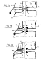
- FIG. 1 represents a simplified diagram of the principle of the invention which consists of forming rigid links L1, L2, L3 on a multifunction plate (10) for positioning in space each of the components C1, C2, C3 which must be mounted blind in housings provided for C1 in a second wall (52), for C2 in the same wall (51) and for C3 in a third wall (53).
- the multi-function plate is positioned in a housing or a recess (510) allowing its positioning on the wall (51).
- This wall (51) is also provided with orifices (511 and 512) of sizes sufficient to allow the passage of the component and the positioning link in space this component.
- each of the components C1, C2, C3 is positioned opposite from their respective accommodation.
- each of the links allows a three-dimensional positioning of component C1, i.e. that the link L1 allows at the same time a displacement in Z and in Y compared to the point of attachment on the plate (10) but also a displacement in X, that is to say perpendicular to the plane formed by the sheet to position, for example, the component C1 at a certain distance above the sheet. It can be the same for the L2 and L3 links.
- One application of the method relates to doors of a vehicle, namely doors, tailgates or hoods engines.
- Component C3 can be, as shown in FIG. 9, a keyboard of switches controlling the electric windows placed on the flat part of an armrest formed in a recess (530).
- Component C1 can be the external control opening doors to operate the vehicle lock.
- FIG. 2 represents an application of this type of the method of the invention in which we find the cutout (521) allowing the fixing of the external part CE on the component C1 which is constituted by the control opening (4) which is mechanically connected to the lock (3) of the door and the assembly being connected by a link (21-22) to the multifunction plate (10).
- the door has a first interior wall (51) provided with two cutouts (511-512) through which we can see the inside of the outer wall at 52 defining the volume of the door in which the glass can be retracted.
- Line (510) defines the outline of the recess forming the means for positioning the multifunction plate (10).
- Well glass is accessible by the lower edge (55) forming the frame of the door.
- a cutout (56) allows to receive the housing (3) lock.
- FIGS. 8A, 8B The part external CE which is fixed on the component (4) is shown in FIGS. 8A, 8B and consists of a covering (53 or 53B) which, using screws, comes sandwich the wall (52) with component C1 and this covering (53) is provided with openings (535) allowing the clipping of an operating member (533) in the additional elements provided for this purpose in the order door opening opening constituting component C1.
- FIG. 2 represents a diagram of the device allowing the setting in work of the method according to the invention.
- the device according to the invention is by example, intended to be mounted on a cassette (1) of an opening element of a vehicle such as a door or a tailgate.
- a vehicle such as a door or a tailgate.
- a door of vehicle consists, in its upper part, of a window frame intended to receive a window and in its lower part, under the frame, of a hollow volume closed consisting of a first wall or external envelope and a inner envelope comprising at least one opening.
- the hollow volume forms a well intended to receive the window when it is lowered.
- a door cassette (1) comprises a wall (10) intended to close the opening formed in the interior wall of the door so as to delimit a closed volume.
- the wall (10) of the cassette (1) is configured to receive at least one connecting means (20, 21, 22) allowing to secure at least one element (3, 4) inside the door and to block all the internal elements (3, 4) in rotation and in translation relative to the cassette (1).
- These interior elements (3, 4) or components are intended for perform specific door functions.
- a first component consists, for example, of the mechanism (3) of the door lock, and a second component is made up of the part technique of the external opening control (4), hereinafter called "WCC".
- the connecting means (20, 21, 22) are designed to either not occupy the space intended for the window, or door well, either to be able to be removed or retracted if they obstruct the door well.
- the means (20, 21, 22) of connection comprise, on the one hand at least one means (21, 22) of fixed link to secure the door components (3, 4) to the wall (10) of the cassette (1) and not closing the door well, and on the other hand to at least one means (20) of removable or retractable connection allowing the locking in rotation and in translation of the component (4) intended to be mounted at inside the outer wall of the door.
- the fixed connection means (21, 22) include, for example, at at least one lug (21, 22) or fixing tab.
- Each leg (21, 22) comprises, on the one hand mounting means with at least one component (3, 4) door, and secondly mounting means, either on the cassette (1), or on another means of connection.
- a first tab (21) mounted on the wall (10) of the cassette (1) secures the mechanism (3) of the door lock
- a second tab (12) mounted on the first tab (21) ensures the joining from the lock to the technical part of the external opening control (4).
- these tabs (21, 22) secure the components (3, 4) of door with the cassette (1) and therefore allow easy installation of the components (3, 4) in the door, intended subsequently to be mounted on this one.
- the legs (21, 22) are shaped so as not to enter the well (54) door.
- the positioning then the complete locking in translation and rotation of the components (3, 4) relative to to the cassette (1) must be secured to avoid any risk of discrepancy, when the final assembly of the components (3, 4) in the door.
- the blocking is ensured by at least one removable connection means (20) or retractable, described in detail later.
- the removable connection means (20) consists of a bar (20) integral with, on the one hand, the external control (4) for opening, and on the other hand from the wall (10) of the cassette (1).
- connection between the bar (20) and the wall (10) of the cassette (1) is provided, for example, by a tongue (12) provided with a hole.
- the tongue is formed in a cutout (11) of the wall (10).
- the hole of determined size and geometry, can be practiced directly in the wall (10).
- the bar (20) is then engaged in the bore (12) of the wall (10), and in a second bore (41) made on part of the exterior opening control (4). So once the components (3, 4) secured to the wall (10) of the cassette (1) by through the tabs (21, 22), this bar (20) blocks the components (3, 4) in an optimal position for fixing in the door.
- this bar (20) on the cassette and on the technical part of the external opening control (4) is such that an operator can remove the bar (20), once all the components (3, 4) are mounted in the door, by through a gripping means (201) located on a first end of the bar (20) and projecting from the outer face of the wall (10) of the cassette (1).
- FIG. 3 shows a cross-sectional view of a first variant embodiment of the device according to the invention.
- the cassette (1) is mounted on the interior wall (51) of a door (5), cut through at least one opening.
- a decorative element (53) or part outside of the door opening control with the handle or control pallet (533) of the technical part (4) of the COE, allowing to open the door (50) and a decorative covering, is, for example, mounted on the outer part of the outer wall (52) of this door (5).
- This part exterior (53) also includes means (530) for mounting the exterior opening control (COE) (4) in the door (5), and comprising for this purpose complementary means (42) for mounting on the external part (53).
- the outer part (53) comprises means (533) to allow attachment to the outer wall (52) of the door (5) and means for mounting the pallet (533b).
- the outer wall (52) can include a deep drawing allowing the positioning and / or centering of the external part (53), during its assembly.
- the outer wall (52) comprises also holes for the passage of COE fasteners on the outer part, so that once the assembly has been carried out, the wall (52) is taken between the outer part (53) and the COE (4), which allows the solidarity of the WCC.
- Fasteners include, for example, pins which also allow the positioning of the COE (4).
- the mechanical connection between the external part (53) and the COE (4) is then carried out by screws screwed into the pins.
- the means (530) of mounting the COE as well as the complementary mounting means (42) are located in the interior volume (54) of the door delimited by the two walls (51, 52) of this one.
- These means (530, 42) for mounting the COE include, by example, on the outer part (53), wells (530) of screws shaped for penetrate into pins (531) made on the COE, the connection between the part external and the COE (4) then being ensured by screws adapted to the wells (530) of screw of the external part (53).
- the first tab (21) is, for example, an integral part of the wall (10) from the cassette (1) and projects into the volume (54) inside the door (5).
- This first tab (21) comprises, for example, two holes (210) intended for mounting the second tab (22) via a system screw / nut, the second tab (22) then comprising two holes (220) complementary.
- the means (20) removable link also consist of a bar, the second of which end (202) collaborates with, for example, a tongue (41) integral with the COE (4) to ensure the translational and rotational locking of all interior components of the door.
- the connection between the bar (20) and a on the one hand the tongue (41) of the COE (4), and on the other hand the wall (10) of the cassette (1) will be described later.
- FIG. 4 represents an exemplary embodiment of a connection means removable.
- a removable connection means is, for example, consisting of a bar (20).
- This bar (20) is, for example, consisting of a cylindrical bar on which are made two flats parallel.
- the dimensions and geometry of the cross-section of the bar (20) are substantially identical to the dimensions and geometry of the bore of the tab or hole (12) in the wall (10, fig. 2) of the cassette (1), and piercing (41, fig. 2) of the COE or piercing the tongue (42, fig. 3) of the WCC.
- Each end (201, 202) of the bar (20) comprises means (201, 202) for gripping or handling consisting, for example, of a handle (201, 202).
- This bar (20) also includes means for lock (203, 204) intended to ensure the mounting and dismounting of the bar (20) on the cassette and, for example, the COE or a tab of the WCC.
- These locking means (203, 204) comprise, for example, two grooves made around the entire circumference of the body of the bar (20).
- the thickness of each groove (203, 204) corresponds substantially to the thickness of the wall (10, fig. 2) of the cassette and the thickness of the tongue of the WCC.
- the dimensions of the grooves (203, 204) are chosen so that the section of the bar (20) is cylindrical at their level. The diameter of the cylinder, moreover, the thickness of the bar (20) is less than or equal.
- FIGS. 5A to 5D represent the different stages of implementation place and removal of the removable connecting means of the exemplary embodiment in Figure 3.
- the bar (20) is, firstly, shown in Figure 4A, introduced between the wall (10) of the cassette, and for example a tongue (42) of the COE, by drilling the wall (10) of the cassette, and by drilling (420) of the tongue (42).
- the introduction of the bar (20) can be carried out either starting by introducing the bar (20) through the hole (120) in the wall (10), either by first introducing the bar (20) through the bore (420) of the tongue (42).
- the introduction of the bar (20), shown in Figure 4B, is performed until the first (203), respectively the second grooves (204) are opposite the bore (120) of the wall (10), respectively of the bore (420) of the tongue (42).
- FIG. 4C represents the bar (20), after a operator rotated it a quarter turn in any direction.
- the bar (20) is blocked in translation since, as shows the cross section (D) made at the level of the first groove, the longitudinal axis (205) of the cross section of the bar (20) is no longer parallel to the axis longitudinal (121) of the bore (120) of the wall (10).
- the bar (20) is locked between the wall (10) and the COE and therefore ensures the mounting and blocking in translation and rotation of the COE with respect to the cassette, which facilitates mounting of the COE and possibly other door components.
- FIGS. 6A to 6C represent the different stages of implementation place and retraction of a first alternative embodiment of a means of retractable link.
- the connecting means ensuring the locking in rotation and in translation is not removable but is retractable, i.e. it is not removed once the door components mounted in the door, but simply operated to release the well (54) door.
- the wall (10) of the cassette comprises an opening (13) extended towards the well (54) of the door by a tube (14).
- the end of this tube (14) located inside the well (54), includes a seal (71) in which is fitted a first end of a nut (7), or threaded sleeve, of which the second end is engaged in a first end of a sleeve (43) practiced in the tongue (42) or extension of the COE.
- Geometry and the dimensions of the sleeve (43) are substantially identical to the geometry and to the dimensions of the nut (7) so that the only movement of the nut (7) in the sleeve (43) or the sliding.
- FIG. 5A represents the positioning step of a door component, for example, the WCC.
- the COE is mounted on the wall (10) of the cassette by the intermediary, in particular of the nut (7). Then the cassette is mounted in the door.
- the next step, for the variant shown on the Figures 5A to 5C, consists of fixing the COE to the door and mounting the part exterior (534) on the exterior wall (52) of the door.
- This step consists, first, to engage the bar (532) thread of the screw (531) fixing the external part (53) in the sleeve (43) of the tongue (42), then into the nut (7).
- the last step shown in Figure 6C, consists of tightening the screw (531).
- This operation then causes the sliding from the nut (7) in the sleeve (43) towards the wall (52), since the screw head (531) abuts against the exterior wall (52) of the door.
- the sliding of the nut (7) then causes the release of the well (54) from the door in which the window (6) can slide.
- a second seal (72) can, for example, be fixed on the tongue (42) opposite the joint (71) of the sleeve (14) of the wall (10) of the cassette.
- This first alternative embodiment therefore allows the fixing of the exterior part and mounting of the COE in the door by an operation of screwing performed by the outer wall (52) of the door.
- FIGS. 7A to 7C represent the different stages of implementation place and retraction of a second alternative embodiment of a means of retractable link.
- This second embodiment allows the fixing of the external part (53) and the mounting of the COE in the door by a screwing operation performed by the wall (10) of the cassette.
- the wall (10) of the cassette remains unchanged from that of the first variant.
- the nut is replaced by a screw (8) whose screw head is accessible through the tube (14) of the wall (10).
- the tongue (42) remains also unchanged from the first variant.
- the contact between the COE and the exterior wall (52) of the door is no longer ensured by the second end of the sleeve (43), but by an extension (44) of the tongue (42).
- the outer part (53) is, by example, a decorative box that hides an opening in the wall (52) outside the door.
- the outer part (53) comprises, on its face not visible from the outside, a sleeve (541) whose dimensions and geometry allow its nesting in the sleeve (43) of the tongue (42) of the WCC.
- the outer part (53) is secured to the COE.
- This connection shown in Figure 6B, consists of fitting the sleeve (541) of the outer part (53) in the sleeve (43) of the tongue (42) of the WCC.
- the outer part (53) is then pressed against the outer wall (52) of the door and the end of the bar (80) is engaged in the sleeve (541) of the outer part (53).
- the final determination of the external part (53), as well as the release of the well (54), represented figure 6C, are obtained by screwing the screw (8) into the sleeve (541) of the part exterior (53) equipped for this purpose, for example, with a threaded insert.
- FIGS. 8A and 8B represent a first, respectively a second, alternative embodiments of an external housing or external part a door open command.
- the part outer (53a, 53b) is mounted on the outer wall (52) of the door by via mounting means comprising, on the one hand on the part exterior (53a, 53b), at least two screw wells (534), and on the other hand, on the wall (52) of the door, corresponding holes (520). These holes (520) also allow the mounting of the COE on the external part (53a, 53b), for example, by means of positioning pins and screws.
- the external part (53a, 53b) also comprises means (535a, 535b) to allow the pallet (533a, 533b) to be linked to the opening control exterior (COE).
- the pallet (533a) is intended for rotate along a vertical axis
- the palette (533b) is intended to pivot along a horizontal axis.
- the method according to the invention includes, first of all, a step in which the components or elements door interiors are mounted on the cassette. This allows in a second step to insert and mount this assembly in the door. Finally, a final step is to release the door well, either by removing the removable means, either by retracting the connecting means ensuring blocking in rotation and translation.
- the variant embodiments shown in FIGS. 6A to 6C, and 7A to 7C, make it possible to carry out the step of mounting the components in the door and the release of the well simultaneously.
- the method and the device according to the invention allow to facilitate the operation of mounting components inside a door. Indeed, all components can be positioned for mounting blind in the door in a single operation which consists in inserting, into the door, the cassette previously fitted with the various components. Finally, the different embodiments of the removable connection means or retractable depend, on the one hand, on the configuration of the components and on the door, and on the other hand the choice of the user as to reuse or not connecting means allowing the blocking of all the components.
Landscapes
- Engineering & Computer Science (AREA)
- Manufacturing & Machinery (AREA)
- Chemical & Material Sciences (AREA)
- Combustion & Propulsion (AREA)
- Transportation (AREA)
- Mechanical Engineering (AREA)
- Lock And Its Accessories (AREA)
- Automobile Manufacture Line, Endless Track Vehicle, Trailer (AREA)
- Automatic Assembly (AREA)
- Vehicle Step Arrangements And Article Storage (AREA)
- Connection Of Plates (AREA)
Abstract
Description
La présente invention concerne un procédé de montage en aveugle d'au moins un composant et un dispositif de mise en oeuvre de ce procédé. Le montage en aveugle de composants est un problème qui se pose aux constructeurs en particulier automobiles. Ce procédé et ce dispositif sont notamment utilisés lors de l'assemblage d'une platine multifonction dans un élément ouvrant pour véhicule. L'élément ouvrant peut-être une porte ou un hayon de véhicule.The present invention relates to a blind mounting method at least one component and one device for implementing this method. The blind assembly of components is a problem for especially automobile manufacturers. This method and this device are especially used when assembling a multi-function plate in a opening element for vehicle. The opening element may be a door or a vehicle tailgate.
Il est connu dans l'art antérieur que le montage des composants disposés, par exemple, dans l'espace intérieur d'une portière est problématique. En effet, l'espace disponible pour manoeuvrer les composants ainsi que les outils pour assurer leur ajustage est réduit. De plus, certains de ces composants, comme par exemple, la commande d'ouverture extérieure, sont positionnés avec une visibilité quasiment nulle. Ainsi, les opérations de montage de ces composants sont longues et fastidieuses. Les risques d'erreurs de montage sont importants.It is known in the prior art that the mounting of the components arranged, for example, in the interior space of a door is problematic. Indeed, the space available to maneuver the components as well as the tools to ensure their adjustment is reduced. In addition, some of these components, such as the exterior opening control, are positioned with almost zero visibility. So the operations of mounting these components are long and tedious. The risks of errors are important.
Par ailleurs, la tendance des constructeurs à regrouper plusieurs fonctions qui doivent être installées dans le véhicule sur des platines multifonctions réduit encore les possibilités d'accès pour les monteurs.In addition, the tendency of manufacturers to group several functions that must be installed in the vehicle on turntables multifunctional further reduces the access possibilities for fitters.
La présente invention a donc pour premier objet de pallier les inconvénients de l'art antérieur en proposant un procédé permettant le positionnement et le montage en aveugle de composants.The primary object of the present invention is therefore to overcome the disadvantages of the prior art by proposing a method allowing the blind positioning and mounting of components.
Ce but est atteint par le fait que le procédé de montage en aveugle d'au moins un composant destiné à être mis en place dans un logement difficilement accessible comprend :
- une étape de liaison tridimensionnelle du composant par un lien avec une platine multifonction;
- une étape de formation de moyens de positionnement de la platine multifonctionnelle dans une première paroi pourvue d'au moins un trou permettant le passage du lien et du composant, le dit lien positionnant dans l'espace le composant pour qu'après positionnement de la platine, le composant soit en place dans le logement;
- une étape de fixation de composants supplémentaires sur le composant.
- a step of three-dimensional connection of the component by a link with a multifunction plate;
- a step of forming means for positioning the multifunctional plate in a first wall provided with at least one hole allowing the passage of the link and of the component, said link positioning the component in space so that after positioning of the plate , the component is in place in the housing;
- a step of fixing additional components to the component.
Selon une autre particularité, le logement est solidaire d'une seconde paroi.According to another particularity, the housing is integral with a second wall.
Selon une autre particularité, la seconde paroi forme avec la première un volume.According to another particular feature, the second wall forms with the first a volume.
Selon une autre particularité, les composants complémentaires sont un composant d'habillage et un composant de manoeuvre.According to another particularity, the complementary components are a covering component and an operating component.
Selon une autre particularité, le volume est un ouvrant de véhicule.According to another particular feature, the volume is a vehicle opening.
Selon une autre particularité, la liaison tridimensionnelle est rigide en X et Z et rigidifiable en Y par une clé.According to another particularity, the three-dimensional connection is rigid in X and Z and stiffenable in Y by a key.
Selon une autre particularité, la platine multifonctionnelle est une cassette de porte de véhicule.According to another particularity, the multifunctional plate is a vehicle door cassette.
Selon une autre caractéristique, le procédé de montage en aveugle d'un composant dans un volume constituant un élément ouvrant, formé d'une première paroi extérieure et d'une deuxième paroi intérieure est caractérisé en ce qu'il comprend :
- une étape de rigidification d'un composant sur une cassette multifonction
- une étape de fixation de la cassette dans un logement prévu sur la deuxième paroi et de positionnement d'un composant sur la face interne de la paroi extérieure de l'élément ouvrant
- une étape de suppression de la rigidification
- une étape de montage des composants extérieurs de manoeuvre et d'habillage.
- a step of stiffening a component on a multifunction cassette
- a step of fixing the cassette in a housing provided on the second wall and positioning of a component on the internal face of the external wall of the opening element
- a step of removing stiffening
- a step of mounting the exterior components for operation and covering.
Selon une autre particularité, un élément ouvrant est une portière ou un hayon, l'étape de suppression de la rigidification libère l'espace entre les deux parois formant un puits pour un élément mobile tel qu'une vitre, un des composants destiné à être monté est la partie technique d'une commande extérieure d'ouverture. According to another particular feature, an opening element is a door or a tailgate, the step of removing stiffening frees the space between the two walls forming a well for a mobile element such as a window, one of the components to be mounted is the technical part of an order exterior opening.
Selon une autre particularité, le procédé comprend une étape de montage d'une partie extérieure de la commande d'ouverture de la porte comprenant un organe de manoeuvre et/ou un habillage à l'extérieur de la portière, le montage étant réalisé par fixation sur la commande d'ouverture extérieure pour enserrer la paroi entre la partie extérieure et la partie technique de la commande extérieure d'ouverture.According to another particular feature, the method comprises a step of mounting of an external part of the door opening control comprising an operating member and / or a covering outside the door, assembly being carried out by fixing on the opening control outer to enclose the wall between the outer part and the technical part of the external opening control.
Selon une autre particularité, un moyen de liaison amovible comprend un barreau comportant des moyens permettant son verrouillage d'une part sur la seconde paroi, et d'autre part sur un des composants destiné à être monté à l'intérieur du volume, ces moyens de verrouillage étant déverrouillables une fois le composant mis en place et fixé dans le volume afin de libérer l'espace entre les deux parois du volume.According to another particularity, a removable connection means comprises a bar comprising means allowing its locking on the one hand on the second wall, and on the other hand on one of the components intended to be mounted at inside the volume, these locking means being unlockable once the component put in place and fixed in the volume in order to free the space between the two walls of the volume.
Selon une autre particularité, l'étape de montage et de solidarisation de l'ensemble formé par la cassette et de tous les éléments intérieurs à l'intérieur d'une portière de véhicule consiste, d'une part à solidariser chaque élément aux parois de la portière, et d'autre part à solidariser, lorsque cela est nécessaire, au moins un mécanisme de chaque élément à un mécanisme de la cassette.According to another particular feature, the step of mounting and joining together the assembly formed by the cassette and all the interior elements inside of a vehicle door consists, firstly, in securing each element to the walls of the door, and on the other hand to be joined, when this is required, at least one mechanism of each element to a mechanism of the cassette.
Un deuxième but de l'invention a pour objet de proposer un dispositif permettant la mise en oeuvre du procédé selon l'invention.A second object of the invention is to propose a device allowing the implementation of the method according to the invention.
Ce deuxième but est atteint par le fait que le dispositif de montage d'au moins un composant à l'intérieur d'un élément ouvrant de véhicule comprend des moyens de liaison amovible du ou des composants à une cassette destinée à être montée sur l'élément ouvrant, les moyens de liaison amovible étant conformés pour assurer le blocage en rotation et en translation par rapport à la cassette du ou des composants à monter à l'intérieur de l'élément ouvrant.This second object is achieved by the fact that the device for mounting at least at least one component inside a vehicle opening element comprises means for removable connection of the component (s) to a cassette intended to be mounted on the opening element, the removable connection means being shaped to ensure rotation and translation locking by relation to the cassette of the component or components to be mounted inside the element opening.
Selon une autre particularité, un moyen de liaison amovible comprend un barreau comportant des moyens permettant son verrouillage d'une part sur la cassette et d'autre part sur un des composants, ces moyens de verrouillage étant déverrouillables une fois tous les composants mis en place dans la portière afin de libérer le puits de circulation de la vitre. According to another particularity, a removable connection means comprises a bar comprising means allowing its locking on the one hand on the cassette and on the other hand on one of the components, these locking means being unlockable once all the components are in place in the door in order to free the glass circulation hole.
Selon une autre particularité, un moyen de liaison escamotable comprend un manchon taraudé assurant, par des moyens de solidarisation, la liaison entre la cassette et un composant intérieur, le taraudage du manchon étant destiné à collaborer avec une vis de fixation à une paroi de la portière d'un des éléments intérieurs, l'escamotage du manchon étant obtenu par vissage de la vis de fixation lors de la solidarisation de l'élément intérieur sur la portière.In another feature, a retractable connecting means includes a threaded sleeve ensuring, by means of securing, the connection between the cassette and an internal component, the thread of the sleeve being intended to collaborate with a screw for fixing to a wall of the door of one of the interior elements, the retraction of the sleeve being obtained by screwing in the fixing screw when the inner element is attached to the door.
Selon une autre particularité, les composants intérieurs de portière comprennent, d'une part la partie technique d'une commande extérieure d'ouverture destinée à être solidarisée à la surface intérieure de la tôle formant la paroi extérieure de la portière, par l'intermédiaire d'une partie extérieure, positionnée sur un embouti de la surface extérieure de la tôle et des moyens de fixation assurant la liaison mécanique entre la partie extérieure et la partie technique de la commande extérieure d'ouverture, et/ou d'autre part le mécanisme de serrure de la portière.In another feature, the interior door components include, on the one hand, the technical part of an external control opening intended to be secured to the inner surface of the sheet forming the exterior wall of the door, by means of an exterior portion, positioned on a stamping of the outer surface of the sheet and the means of fixing ensuring the mechanical connection between the external part and the part external opening control technique, and / or the door lock mechanism.
Selon une autre particularité, la partie extérieure est constituée d'un habillage et d'un organe de préhension.According to another particularity, the external part consists of a dressing and a gripping member.
Selon une autre particularité, la paroi extérieure de la portière comprend un renfoncement ou une découpe de centrage de la partie extérieure, cette dernière comportant des puits de centrage qui pénètrent dans des broches de la partie technique de la commande d'ouverture extérieure, les puits recevant une vis de liaison de la partie extérieure avec la partie technique de la commande extérieure d'ouverture.In another feature, the exterior wall of the door includes a recess or a centering cutout of the part exterior, the latter comprising centering wells which penetrate into pins of the technical part of the exterior opening control, the well receiving a screw connecting the external part with the technical part of the external opening control.
D'autres particularités et avantages de la présente invention apparaítront plus clairement à la lecture de la description ci-après faite en référence aux dessins annexés dans lesquels :
- la figure 1 représente un schéma simplifié du dispositif permettant la mise en oeuvre du procédé.
- la figure 2 représente un schéma du dispositif permettant la mise en oeuvre du procédé selon l'invention,
- la figure 3 représente une vue en coupe transversale d'une première variante de réalisation du dispositif selon l'invention,
- la figure 4 représente un exemple de réalisation d'un moyen de liaison amovible,
- les figures 5A à 5D représentent les différentes étapes de mise en place et d'enlèvement de l'exemple de réalisation du moyen de liaison amovible de la figure 4,
- les figures 6A à 6C représentent les différentes étapes de mise en place et d'escamotage d'une première variante de réalisation d'un moyen de liaison escamotable,
- les figures 7A à 7C représentent les différentes étapes de mise en place et d'escamotage d'une deuxième variante de réalisation d'un moyen de liaison escamotable,
- les figures 8A et 8B représentent une première, respectivement une deuxième variante, de réalisation d'un boítier extérieur d'une commande d'ouverture de porte.
- la figure 9 représente une vue en perspective d'une utilisation du procédé défini par rapport à la figure 1.
- FIG. 1 represents a simplified diagram of the device allowing the implementation of the method.
- FIG. 2 represents a diagram of the device allowing the implementation of the method according to the invention,
- FIG. 3 represents a cross-sectional view of a first alternative embodiment of the device according to the invention,
- FIG. 4 represents an exemplary embodiment of a removable connection means,
- FIGS. 5A to 5D represent the different stages of setting up and removing the example of embodiment of the removable connection means of FIG. 4,
- FIGS. 6A to 6C represent the different stages of setting up and retracting a first variant embodiment of a retractable connecting means,
- FIGS. 7A to 7C represent the different stages of setting up and retracting a second variant embodiment of a retractable connecting means,
- Figures 8A and 8B show a first, respectively a second variant, of an external housing of a door opening control.
- FIG. 9 represents a perspective view of a use of the method defined with respect to FIG. 1.
La figure 1 représente un schéma simplifié du principe de l'invention qui consiste à former sur une platine multifonction (10) des liens L1, L2, L3 rigides permettant de positionner dans l'espace chacun des composants C1, C2, C3 qui doivent être montés en aveugle dans des logements prévus pour C1 dans une deuxième paroi (52), pour C2 dans la même paroi (51) et pour C3 dans une troisième paroi (53). La platine multifonction vient se positionner dans un logement ou un renfoncement (510) permettant son positionnement sur la paroi (51). Cette paroi (51) est également pourvue d'orifices (511 et 512) de tailles suffisantes pour permettre le passage du composant et du lien positionnant dans l'espace ce composant. Lorsque la platine est mise en place dans son logement (510), chacun des composants C1, C2, C3 est positionné en vis-à-vis de son logement respectif. Le procédé consiste ensuite à rendre le composant solidaire d'une partie extérieure qui viendra prendre en sandwich la paroi (52) entre C1 et cette partie extérieure. Le lecteur doit bien réaliser que chacun des liens permet un positionnement tridimensionnel du composant C1, c'est à dire que le lien L1 permet à la fois un déplacement en Z et en Y par rapport au point d'attache sur la platine (10) mais également un déplacement en X, c'est à dire perpendiculaire au plan formé par la feuille pour positionner, par exemple, le composant C1 à une certaine distance au-dessus de la feuille. Il peut en être de même pour les liens L2 et L3. Une application du procédé concerne les ouvrants d'un véhicule, à savoir les portières, les hayons ou les capots moteurs. Ainsi dans une portière, la paroi (52) et la paroi externe de la portière, la paroi (53) constitue l'habillage intérieur de la portière. Le composant C3 peut être, comme représenté figure 9, un clavier d'interrupteurs commandant les vitres électriques placées sur la partie plane d'un accoudoir formé dans un renfoncement (530). Le composant C1 peut être la commande extérieure d'ouverture de portières permettant d'actionner la serrure du véhicule.FIG. 1 represents a simplified diagram of the principle of the invention which consists of forming rigid links L1, L2, L3 on a multifunction plate (10) for positioning in space each of the components C1, C2, C3 which must be mounted blind in housings provided for C1 in a second wall (52), for C2 in the same wall (51) and for C3 in a third wall (53). The multi-function plate is positioned in a housing or a recess (510) allowing its positioning on the wall (51). This wall (51) is also provided with orifices (511 and 512) of sizes sufficient to allow the passage of the component and the positioning link in space this component. When the plate is placed in its housing (510), each of the components C1, C2, C3 is positioned opposite from their respective accommodation. The process then consists in rendering the component integral with an external part which will sandwich the wall (52) between C1 and this outer part. The reader must realize that each of the links allows a three-dimensional positioning of component C1, i.e. that the link L1 allows at the same time a displacement in Z and in Y compared to the point of attachment on the plate (10) but also a displacement in X, that is to say perpendicular to the plane formed by the sheet to position, for example, the component C1 at a certain distance above the sheet. It can be the same for the L2 and L3 links. One application of the method relates to doors of a vehicle, namely doors, tailgates or hoods engines. Thus in a door, the wall (52) and the external wall of the door, the wall (53) constitutes the interior trim of the door. Component C3 can be, as shown in FIG. 9, a keyboard of switches controlling the electric windows placed on the flat part of an armrest formed in a recess (530). Component C1 can be the external control opening doors to operate the vehicle lock.
La figure 2 représente une application de ce type du procédé de l'invention dans laquelle on retrouve la découpe (521) permettant la fixation de la partie extérieure CE sur le composant C1 qui est constitué par la commande d'ouverture extérieure (4) laquelle est reliée mécaniquement à la serrure (3) de la portière et l'ensemble étant relié par un lien (21-22) à la platine multifonction (10). La portière comporte une première paroi intérieure (51) pourvue de deux découpes (511-512) à travers lesquelles on peut apercevoir la face intérieure de la paroi extérieure à 52 définissant le volume de la portière dans laquelle la vitre peut s'escamoter. La ligne (510) définit le contour du renfoncement formant les moyens de positionnement de la platine multifonction (10). Le puits de vitre est accessible par le bord inférieur (55) formant le cadre de la portière. Une découpe (56) permet de recevoir le boítier (3) de serrure. La partie extérieure CE qui vient se fixer sur le composant (4) est représentée figures 8A, 8B et est constituée d'un habillage (53 ou 53B) qui, à l'aide de vis, vient prendre en sandwich la paroi (52) avec le composant C1 et cet habillage (53) est pourvu d'ouvertures (535) permettant le clipsage d'un organe de manoeuvre (533) dans les éléments complémentaires prévus à cet effet dans la commande d'ouverture extérieure de porte constituant le composant C1.FIG. 2 represents an application of this type of the method of the invention in which we find the cutout (521) allowing the fixing of the external part CE on the component C1 which is constituted by the control opening (4) which is mechanically connected to the lock (3) of the door and the assembly being connected by a link (21-22) to the multifunction plate (10). The door has a first interior wall (51) provided with two cutouts (511-512) through which we can see the inside of the outer wall at 52 defining the volume of the door in which the glass can be retracted. Line (510) defines the outline of the recess forming the means for positioning the multifunction plate (10). Well glass is accessible by the lower edge (55) forming the frame of the door. A cutout (56) allows to receive the housing (3) lock. The part external CE which is fixed on the component (4) is shown in FIGS. 8A, 8B and consists of a covering (53 or 53B) which, using screws, comes sandwich the wall (52) with component C1 and this covering (53) is provided with openings (535) allowing the clipping of an operating member (533) in the additional elements provided for this purpose in the order door opening opening constituting component C1.
La figure 2 représente un schéma du dispositif permettant la mise en oeuvre du procédé selon l'invention. Le dispositif, selon l'invention, est par exemple, destiné à être monté sur une cassette (1) d'un élément ouvrant d'un véhicule tel qu'une portière ou un hayon. A titre d'exemple, la description est réalisée pour une portière mais reste valable pour un hayon. Une portière de véhicule est constituée, dans sa partie haute, d'un cadre de fenêtre destiné à recevoir une vitre et dans sa partie basse, sous le cadre, d'un volume creux fermé constitué d'une première paroi ou enveloppe extérieure et d'une enveloppe intérieure comportant au moins une ouverture. Le volume creux forme un puits destiné à recevoir la vitre lorsque celle-ci est abaissée. En règle générale, une cassette (1) de portière comprend une paroi (10) destinée à fermer l'ouverture formée dans la paroi intérieure de la portière de façon à délimiter un volume fermé. Selon l'invention, la paroi (10) de la cassette (1) est conformée pour recevoir au moins un moyen (20, 21, 22) de liaison permettant de solidariser au moins un élément (3, 4) intérieur de portière et de bloquer tous les éléments (3, 4) intérieurs en rotation et en translation par rapport à la cassette (1). Ces éléments (3, 4) intérieurs ou composants sont destinés à assurer des fonctions particulières de la portière. A titre d'exemple non limitatif, un premier composant est constitué, par exemple, du mécanisme (3) de la serrure de la portière, et un deuxième composant est constitué de la partie technique de la commande extérieure d'ouverture (4), par la suite appelée "COE". Les moyens (20, 21, 22) de liaison sont conformés pour, soit ne pas occuper l'espace destiné à la vitre, ou puits de la portière, soit pour pouvoir être enlevés ou escamotés s'ils entravent le puits de la portière. Ainsi, les moyens (20, 21, 22) de liaison comprennent, d'une part au moins un moyen (21, 22) de liaison fixe permettant de solidariser les composants (3, 4) de portière à la paroi (10) de la cassette (1) et n'obturant pas le puits de portière, et d'autre part au moins un moyen (20) de liaison amovible ou escamotable permettant le blocage en rotation et en translation du composant (4) destiné à être monté à l'intérieur de la paroi externe de la portière.FIG. 2 represents a diagram of the device allowing the setting in work of the method according to the invention. The device according to the invention is by example, intended to be mounted on a cassette (1) of an opening element of a vehicle such as a door or a tailgate. As an example, the description is made for a door but remains valid for a tailgate. A door of vehicle consists, in its upper part, of a window frame intended to receive a window and in its lower part, under the frame, of a hollow volume closed consisting of a first wall or external envelope and a inner envelope comprising at least one opening. The hollow volume forms a well intended to receive the window when it is lowered. In good standing general, a door cassette (1) comprises a wall (10) intended to close the opening formed in the interior wall of the door so as to delimit a closed volume. According to the invention, the wall (10) of the cassette (1) is configured to receive at least one connecting means (20, 21, 22) allowing to secure at least one element (3, 4) inside the door and to block all the internal elements (3, 4) in rotation and in translation relative to the cassette (1). These interior elements (3, 4) or components are intended for perform specific door functions. By way of nonlimiting example, a first component consists, for example, of the mechanism (3) of the door lock, and a second component is made up of the part technique of the external opening control (4), hereinafter called "WCC". The connecting means (20, 21, 22) are designed to either not occupy the space intended for the window, or door well, either to be able to be removed or retracted if they obstruct the door well. So the means (20, 21, 22) of connection comprise, on the one hand at least one means (21, 22) of fixed link to secure the door components (3, 4) to the wall (10) of the cassette (1) and not closing the door well, and on the other hand to at least one means (20) of removable or retractable connection allowing the locking in rotation and in translation of the component (4) intended to be mounted at inside the outer wall of the door.
Les moyens (21, 22) de liaison fixe comprennent, par exemple, au moins une patte (21, 22) ou languette de fixation. Chaque patte (21, 22) comprend, d'une part des moyens de montage avec au moins un composant (3, 4) de portière, et d'autre part des moyens de montage, soit sur la cassette (1), soit sur un autre moyen de liaison. Dans l'exemple de réalisation de la figure 1, une première patte (21) montée sur la paroi (10) de la cassette (1) assure la solidarisation du mécanisme (3) de la serrure de la portière, et une deuxième patte (12) montée sur la première patte (21) assure la solidarisation de la serrure à la partie technique de la commande extérieure (4) d'ouverture. Ainsi, ces pattes (21, 22) assurent une solidarisation des composants (3, 4) de portière avec la cassette (1) et permettent donc une mise en place aisée des composants (3, 4) dans la portière, destinés, par la suite, à être montés sur celle-ci. Ces pattes (21, 22) sont conformées pour ne pas pénétrer dans le puits (54) de portière. Cependant, compte tenu de la contrainte liée à la libération du puits de portière, pour le passage de la vitre (6), le positionnement puis le blocage complet en translation et en rotation des composants (3, 4) par rapport à la cassette (1) doivent être assurés pour éviter tout risque de décalage, lors du montage définitif des composants (3, 4) dans la portière. Pour ce faire, le blocage est assuré par au moins un moyen (20) de liaison amovible ou escamotable, décrit en détails ultérieurement. Dans l'exemple de réalisation représenté figure 1, le moyen (20) de liaison amovible est constitué d'un barreau (20) solidaire, d'une part de la commande extérieure (4) d'ouverture, et d'autre part de la paroi (10) de la cassette (1). La liaison entre le barreau (20) et la paroi (10) de la cassette (1) est assurée, par exemple, par une languette (12) pourvue d'un perçage. La languette est formée dans une découpe (11) de la paroi (10). Le perçage, de dimension et géométrie déterminées, peut être pratiqué directement dans la paroi (10). Le barreau (20) est alors engagé dans le perçage (12) de la paroi (10), et dans un second perçage (41) pratiqué sur une partie de la commande extérieure d'ouverture (4). Ainsi, une fois les composants (3, 4) solidarisés à la paroi (10) de la cassette (1) par l'intermédiaire des pattes (21, 22), ce barreau (20) assure le blocage des composants (3, 4) dans une position optimale pour leur fixation dans la portière. Le montage de ce barreau (20) sur la cassette et sur la partie technique de la commande extérieure (4) d'ouverture est tel qu'un opérateur peut retirer le barreau (20), une fois tous les composants (3, 4) montés dans la portière, par l'intermédiaire d'un moyen (201) de préhension situé sur une première extrémité du barreau (20) et en saillie par rapport à la face extérieure de la paroi (10) de la cassette (1).The fixed connection means (21, 22) include, for example, at at least one lug (21, 22) or fixing tab. Each leg (21, 22) comprises, on the one hand mounting means with at least one component (3, 4) door, and secondly mounting means, either on the cassette (1), or on another means of connection. In the example of realization of the Figure 1, a first tab (21) mounted on the wall (10) of the cassette (1) secures the mechanism (3) of the door lock, and a second tab (12) mounted on the first tab (21) ensures the joining from the lock to the technical part of the external opening control (4). Thus, these tabs (21, 22) secure the components (3, 4) of door with the cassette (1) and therefore allow easy installation of the components (3, 4) in the door, intended subsequently to be mounted on this one. These legs (21, 22) are shaped so as not to enter the well (54) door. However, given the constraint linked to the release of the door well, for the passage of the window (6), the positioning then the complete locking in translation and rotation of the components (3, 4) relative to to the cassette (1) must be secured to avoid any risk of discrepancy, when the final assembly of the components (3, 4) in the door. To do this, the blocking is ensured by at least one removable connection means (20) or retractable, described in detail later. In the example of realization shown in Figure 1, the removable connection means (20) consists of a bar (20) integral with, on the one hand, the external control (4) for opening, and on the other hand from the wall (10) of the cassette (1). The connection between the bar (20) and the wall (10) of the cassette (1) is provided, for example, by a tongue (12) provided with a hole. The tongue is formed in a cutout (11) of the wall (10). The hole, of determined size and geometry, can be practiced directly in the wall (10). The bar (20) is then engaged in the bore (12) of the wall (10), and in a second bore (41) made on part of the exterior opening control (4). So once the components (3, 4) secured to the wall (10) of the cassette (1) by through the tabs (21, 22), this bar (20) blocks the components (3, 4) in an optimal position for fixing in the door. The mounting of this bar (20) on the cassette and on the technical part of the external opening control (4) is such that an operator can remove the bar (20), once all the components (3, 4) are mounted in the door, by through a gripping means (201) located on a first end of the bar (20) and projecting from the outer face of the wall (10) of the cassette (1).
La figure 3 représente une vue en coupe transversale d'une première variante de réalisation du dispositif selon l'invention. Dans cette représentation, la cassette (1) est montée sur la paroi (51) intérieure d'une portière (5), découpée selon au moins une ouverture. Un élément (53) décoratif ou partie extérieure de la commande d'ouverture de la porte comportant la poignée ou palette (533) de commande de la partie (4) technique de la COE, permettant d'ouvrir la portière (50) et un habillage décoratif, est, par exemple, monté sur la partie externe de la paroi (52) extérieure de cette portière (5). Cette partie extérieure (53) comprend également des moyens (530) permettant le montage de la commande extérieure d'ouverture (COE) (4) dans la portière (5), et comportant à cet effet, des moyens (42) complémentaires de montage sur la partie extérieure (53). La partie extérieure (53) comprend des moyens (533) pour permettre la fixation sur la paroi extérieure (52) de la portière (5) et des moyens de montage de la palette (533b). La paroi (52) extérieure peut comprendre un embouti permettant le positionnement et/ou le centrage de la partie extérieure (53), lors de son montage. La paroi (52) extérieure comprend également des perçages destinés au passage d'éléments de fixation de la COE sur la partie extérieure, de sorte qu'une fois le montage effectué, la paroi (52) est prise entre la partie extérieure (53) et la COE (4), ce qui permet la solidarisation de la COE. Les éléments de fixation comprennent, par exemple, des broches qui permettent également le positionnement de la COE (4). La liaison mécanique entre la partie extérieure (53) et la COE (4) est alors réalisée par des vis vissées dans les broches. Les moyens (530) de montage de la COE ainsi que les moyens (42) complémentaires de montage sont situés dans le volume (54) intérieur de la portière délimité par les deux parois (51, 52) de celle-ci. Ces moyens (530, 42) de montage de la COE comprennent, par exemple, sur la partie extérieure (53), des puits (530) de vis conformés pour pénétrer dans des broches (531) réalisées sur la COE, la liaison entre la partie extérieure et la COE (4) étant assurée alors par des vis adaptées aux puits (530) de vis de la partie extérieure (53). Dans cette première variante de réalisation, la première patte (21) fait, par exemple, partie intégrante de la paroi (10) de la cassette (1) et fait saillie dans le volume (54) intérieur de la portière (5). Cette première patte (21) comprend, par exemple, deux perçages (210) destinés au montage de la deuxième patte (22) par l'intermédiaire d'un système vis/écrou, la deuxième patte (22) comportant alors deux perçages (220) complémentaires. Dans cette première variante de réalisation, les moyens (20) de liaison amovible sont également constitués d'un barreau dont la deuxième extrémité (202) collabore avec, par exemple, une languette (41) solidaire de la COE (4) pour assurer le blocage en translation et en rotation de tous les composants intérieurs de la portière. La liaison entre le barreau (20) et d'une part la languette (41) de la COE (4), et d'autre part la paroi (10) de la cassette (1) sera décrite ultérieurement.Figure 3 shows a cross-sectional view of a first variant embodiment of the device according to the invention. In this representation, the cassette (1) is mounted on the interior wall (51) of a door (5), cut through at least one opening. A decorative element (53) or part outside of the door opening control with the handle or control pallet (533) of the technical part (4) of the COE, allowing to open the door (50) and a decorative covering, is, for example, mounted on the outer part of the outer wall (52) of this door (5). This part exterior (53) also includes means (530) for mounting the exterior opening control (COE) (4) in the door (5), and comprising for this purpose complementary means (42) for mounting on the external part (53). The outer part (53) comprises means (533) to allow attachment to the outer wall (52) of the door (5) and means for mounting the pallet (533b). The outer wall (52) can include a deep drawing allowing the positioning and / or centering of the external part (53), during its assembly. The outer wall (52) comprises also holes for the passage of COE fasteners on the outer part, so that once the assembly has been carried out, the wall (52) is taken between the outer part (53) and the COE (4), which allows the solidarity of the WCC. Fasteners include, for example, pins which also allow the positioning of the COE (4). The mechanical connection between the external part (53) and the COE (4) is then carried out by screws screwed into the pins. The means (530) of mounting the COE as well as the complementary mounting means (42) are located in the interior volume (54) of the door delimited by the two walls (51, 52) of this one. These means (530, 42) for mounting the COE include, by example, on the outer part (53), wells (530) of screws shaped for penetrate into pins (531) made on the COE, the connection between the part external and the COE (4) then being ensured by screws adapted to the wells (530) of screw of the external part (53). In this first variant of embodiment, the first tab (21) is, for example, an integral part of the wall (10) from the cassette (1) and projects into the volume (54) inside the door (5). This first tab (21) comprises, for example, two holes (210) intended for mounting the second tab (22) via a system screw / nut, the second tab (22) then comprising two holes (220) complementary. In this first variant, the means (20) removable link also consist of a bar, the second of which end (202) collaborates with, for example, a tongue (41) integral with the COE (4) to ensure the translational and rotational locking of all interior components of the door. The connection between the bar (20) and a on the one hand the tongue (41) of the COE (4), and on the other hand the wall (10) of the cassette (1) will be described later.
La figure 4 représente un exemple de réalisation d'un moyen de liaison amovible. Comme expliqué précédemment, un moyen de liaison amovible est, par exemple, constitué d'un barreau (20). Ce barreau (20) est, par exemple, constitué d'une barre cylindrique sur laquelle sont pratiqués deux méplats parallèles. Les dimensions et la géométrie de la section du barreau (20) sont sensiblement identiques aux dimensions et géométrie du perçage de la languette ou du perçage (12) de la paroi (10, fig. 2) de la cassette (1), et du perçage (41, fig. 2) de la COE ou du perçage de la languette (42, fig. 3) de la COE. Chaque extrémité (201, 202) du barreau (20) comprend des moyens (201, 202) de préhension ou de manipulation constitués, par exemple, d'une anse (201, 202). Ce barreau (20) comprend également des moyens de verrouillage (203, 204) destinés à assurer le montage et le démontage du barreau (20) sur la cassette et, par exemple, la COE ou une languette de la COE. Ces moyens de verrouillage (203, 204) comprennent, par exemple, deux saignées pratiquées sur toute la circonférence du corps du barreau (20). L'épaisseur de chaque saignée (203, 204) correspond sensiblement à l'épaisseur de la paroi (10, fig. 2) de la cassette et à l'épaisseur de la languette de la COE. Les dimensions des saignées (203, 204) sont choisies pour que la section du barreau (20) soit cylindrique à leur niveau. Le diamètre du cylindre, par ailleurs, est inférieur ou égal l'épaisseur du barreau (20). FIG. 4 represents an exemplary embodiment of a connection means removable. As explained above, a removable connection means is, for example, consisting of a bar (20). This bar (20) is, for example, consisting of a cylindrical bar on which are made two flats parallel. The dimensions and geometry of the cross-section of the bar (20) are substantially identical to the dimensions and geometry of the bore of the tab or hole (12) in the wall (10, fig. 2) of the cassette (1), and piercing (41, fig. 2) of the COE or piercing the tongue (42, fig. 3) of the WCC. Each end (201, 202) of the bar (20) comprises means (201, 202) for gripping or handling consisting, for example, of a handle (201, 202). This bar (20) also includes means for lock (203, 204) intended to ensure the mounting and dismounting of the bar (20) on the cassette and, for example, the COE or a tab of the WCC. These locking means (203, 204) comprise, for example, two grooves made around the entire circumference of the body of the bar (20). The thickness of each groove (203, 204) corresponds substantially to the thickness of the wall (10, fig. 2) of the cassette and the thickness of the tongue of the WCC. The dimensions of the grooves (203, 204) are chosen so that the section of the bar (20) is cylindrical at their level. The diameter of the cylinder, moreover, the thickness of the bar (20) is less than or equal.
Les figures 5A à 5D représentent les différentes étapes de mise en place et d'enlèvement du moyen de liaison amovible de l'exemple de réalisation de la figure 3. Le barreau (20) est, dans un premier temps, représenté figure 4A, introduit entre la paroi (10) de la cassette, et par exemple une languette (42) de la COE, par le perçage de la paroi (10) de la cassette, et par le perçage (420) de la languette (42). L'introduction du barreau (20) peut être réalisée soit en commençant par introduire le barreau (20) par le perçage (120) de la paroi (10), soit en commençant par introduire le barreau (20) par le perçage (420) de la languette (42). L'introduction du barreau (20), représentée figure 4B, est réalisée jusqu'à ce que la première (203), respectivement la deuxième saignées (204) soient en face du perçage (120) de la paroi (10), respectivement du perçage (420) de la languette (42). A ce stade, le barreau (20) peut donc tourner sur son axe (200) longitudinal. En effet, au niveau des saignées (203, 204), les dimensions du barreau (20) sont inférieures aux dimensions respectives du perçage (120) de la paroi (10) et du perçage (420) de la languette (42). Ainsi, la figure 4C représente le barreau (20), après qu'un opérateur l'ait fait tourner d'un quart de tour selon n'importe quel sens. Une fois la rotation exécutée, le barreau (20) est bloqué en translation puisque, comme le montre la coupe (D) transversale réalisée au niveau de la première saignée, l'axe longitudinal (205) de la section du barreau (20) n'est plus parallèle à l'axe longitudinal (121) du perçage (120) de la paroi (10). Dans cette position, le barreau (20) est verrouillé entre la paroi (10) et la COE et assure donc le montage et le blocage en translation et en rotation de la COE par rapport à la cassette, ce qui facilite le montage de la COE et éventuellement, des autres composants de la portière. Pour enlever le barreau (20) et ainsi libérer le puits (54) de la portière, il suffit de faire tourner le barreau (20) d'un nouveau quart de tour pour que l'axe longitudinal de la section du barreau (20) soit parallèle à l'axe longitudinal du perçage (120) de la paroi (10). Une fois la rotation exécutée, on se retrouve dans la configuration représentée figure 4B. Alors, le barreau (20) n'est plus bloqué en translation et peut être retiré, par exemple, dans le sens inverse de celui où il a été introduit. FIGS. 5A to 5D represent the different stages of implementation place and removal of the removable connecting means of the exemplary embodiment in Figure 3. The bar (20) is, firstly, shown in Figure 4A, introduced between the wall (10) of the cassette, and for example a tongue (42) of the COE, by drilling the wall (10) of the cassette, and by drilling (420) of the tongue (42). The introduction of the bar (20) can be carried out either starting by introducing the bar (20) through the hole (120) in the wall (10), either by first introducing the bar (20) through the bore (420) of the tongue (42). The introduction of the bar (20), shown in Figure 4B, is performed until the first (203), respectively the second grooves (204) are opposite the bore (120) of the wall (10), respectively of the bore (420) of the tongue (42). At this point, the bar (20) can therefore rotate on its longitudinal axis (200). Indeed, at the level of grooves (203, 204), the dimensions of the bar (20) are less than respective dimensions of the bore (120) of the wall (10) and of the bore (420) of the tongue (42). Thus, FIG. 4C represents the bar (20), after a operator rotated it a quarter turn in any direction. Once the rotation performed, the bar (20) is blocked in translation since, as shows the cross section (D) made at the level of the first groove, the longitudinal axis (205) of the cross section of the bar (20) is no longer parallel to the axis longitudinal (121) of the bore (120) of the wall (10). In this position, the bar (20) is locked between the wall (10) and the COE and therefore ensures the mounting and blocking in translation and rotation of the COE with respect to the cassette, which facilitates mounting of the COE and possibly other door components. To remove the bar (20) and thus free the well (54) of the door, just rotate the bar (20) a new quarter so that the longitudinal axis of the cross-section of the bar (20) is parallel to the longitudinal axis of the bore (120) of the wall (10). Once the rotation executed, we find ourselves in the configuration shown in FIG. 4B. Therefore the bar (20) is no longer blocked in translation and can be removed, for example, in the opposite direction to that in which it was introduced.
Les figures 6A à 6C représentent les différentes étapes de mise en place et d'escamotage d'une première variante de réalisation d'un moyen de liaison escamotable. Dans cette variante de réalisation, le moyen de liaison assurant le blocage en rotation et en translation n'est pas amovible mais est escamotable, c'est-à-dire qu'il n'est pas retiré une fois les composants de porte montés dans la portière, mais simplement manoeuvré pour libérer le puits (54) de portière. A cet effet, la paroi (10) de la cassette comprend une ouverture (13) prolongée vers le puits (54) de la portière par un tube (14). L'extrémité de ce tube (14) situé à l'intérieur du puits (54), comprend un joint (71) dans lequel est emboítée une première extrémité d'un écrou (7), ou manchon taraudé, dont la deuxième extrémité est engagée dans une première extrémité d'un manchon (43) pratiqué dans la languette (42) ou extension de la COE. La géométrie et les dimensions du manchon (43) sont sensiblement identiques à la géométrie et aux dimensions de l'écrou (7) de sorte que le seul mouvement de l'écrou (7) dans le manchon (43) soit le coulissement. La deuxième extrémité du manchon (43) est en vis-à-vis d'un perçage (521) pratiqué dans la paroi (52) extérieure de la portière et destiné à recevoir une vis (531) permettant la fixation, sur la paroi (52) extérieure de la portière, de la partie extérieure (53) sur laquelle est montée la palette (533b). La figure 5A représente l'étape de positionnement d'un composant de portière, par exemple, la COE. Comme expliqué précédemment, la COE est montée sur la paroi (10) de la cassette par l'intermédiaire, notamment de l'écrou (7). Puis, la cassette est montée dans la portière. L'étape suivante, pour la variante de réalisation représentée sur les figures 5A à 5C, consiste à fixer la COE à la portière et à monter la partie extérieure (534) sur la paroi (52) extérieure de la portière. Cette étape, représentée figure 5B, consiste, dans un premier temps, à engager le barreau (532) fileté de la vis (531) de fixation de la partie extérieure (53) dans le manchon (43) de la languette (42), puis dans l'écrou (7). Lorsque la vis (531) est engagée de cette manière, la tête de vis est alors en butée contre la paroi (52) extérieure de la portière. La dernière étape, représentée figure 6C, consiste à visser la vis (531). Cette opération provoque alors le coulissement de l'écrou (7) dans le manchon (43) vers la paroi (52), puisque la tête de vis (531) est en butée contre la paroi (52) extérieure de la portière. Le coulissement de l'écrou (7) provoque alors la libération du puits (54) de la portière dans lequel la vitre (6) peut coulisser. Un deuxième joint (72) peut, par exemple, être fixé sur la languette (42) en vis-à-vis du joint (71) du manchon (14) de la paroi (10) de la cassette. Ces deux joints (71, 72) assurent une protection de la vitre (6) contre les éventuels chocs.FIGS. 6A to 6C represent the different stages of implementation place and retraction of a first alternative embodiment of a means of retractable link. In this alternative embodiment, the connecting means ensuring the locking in rotation and in translation is not removable but is retractable, i.e. it is not removed once the door components mounted in the door, but simply operated to release the well (54) door. For this purpose, the wall (10) of the cassette comprises an opening (13) extended towards the well (54) of the door by a tube (14). The end of this tube (14) located inside the well (54), includes a seal (71) in which is fitted a first end of a nut (7), or threaded sleeve, of which the second end is engaged in a first end of a sleeve (43) practiced in the tongue (42) or extension of the COE. Geometry and the dimensions of the sleeve (43) are substantially identical to the geometry and to the dimensions of the nut (7) so that the only movement of the nut (7) in the sleeve (43) or the sliding. The second end of the sleeve (43) is opposite a bore (521) made in the outer wall (52) of the door and intended to receive a screw (531) allowing the fixing, on the outer wall (52) of the door, of the outer part (53) on which is mounted the pallet (533b). FIG. 5A represents the positioning step of a door component, for example, the WCC. As explained previously, the COE is mounted on the wall (10) of the cassette by the intermediary, in particular of the nut (7). Then the cassette is mounted in the door. The next step, for the variant shown on the Figures 5A to 5C, consists of fixing the COE to the door and mounting the part exterior (534) on the exterior wall (52) of the door. This step, shown in Figure 5B, consists, first, to engage the bar (532) thread of the screw (531) fixing the external part (53) in the sleeve (43) of the tongue (42), then into the nut (7). When the screw (531) is engaged in this way, the screw head is then in abutment against the wall (52) outside the door. The last step, shown in Figure 6C, consists of tightening the screw (531). This operation then causes the sliding from the nut (7) in the sleeve (43) towards the wall (52), since the screw head (531) abuts against the exterior wall (52) of the door. The sliding of the nut (7) then causes the release of the well (54) from the door in which the window (6) can slide. A second seal (72) can, for example, be fixed on the tongue (42) opposite the joint (71) of the sleeve (14) of the wall (10) of the cassette. These two seals (71, 72) provide a protection of the window (6) against possible shocks.
Cette première variante de réalisation permet donc la fixation de la partie extérieure et le montage de la COE dans la portière par une opération de vissage réalisée par la paroi (52) extérieure de la portière.This first alternative embodiment therefore allows the fixing of the exterior part and mounting of the COE in the door by an operation of screwing performed by the outer wall (52) of the door.
Les figures 7A à 7C représentent les différentes étapes de mise en place et d'escamotage d'une deuxième variante de réalisation d'un moyen de liaison escamotable. Cette deuxième variante de réalisation permet la fixation de la partie extérieure (53) et le montage de la COE dans la portière par une opération de vissage réalisée par la paroi (10) de la cassette. A cet effet, la paroi (10) de la cassette reste inchangée par rapport à celle de la première variante. En revanche, l'écrou est remplacé par une vis (8) dont la tête de vis est accessible par le tube (14) de la paroi (10). La languette (42) reste également inchangée par rapport à la première variante. En revanche, le contact entre la COE et la paroi (52) extérieure de la portière n'est plus assuré par la deuxième extrémité du manchon (43), mais par une extension (44) de la languette (42). Dans cette deuxième variante, la partie extérieure (53) est, par exemple, un boítier décor qui masque une ouverture pratiquée dans la paroi (52) extérieure de la portière. La partie extérieure (53) comprend, sur sa face non visible de l'extérieur, un manchon (541) dont les dimensions et la géométrie permettent son emboítement dans le manchon (43) de la languette (42) de la COE. Ainsi, après le montage de la COE sur la paroi (10) de la cassette, représenté figure 7A, et réalisé de façon similaire à la première variante de réalisation, la partie extérieure (53) est solidarisée avec la COE. Cette solidarisation, représentée figure 6B, consiste à emmancher le manchon (541) de la partie extérieure (53) dans le manchon (43) de la languette (42) de la COE. Une fois solidarisée, la partie extérieure (53) est alors en appui contre la paroi (52) extérieure de la portière et l'extrémité du barreau (80) est engagée dans le manchon (541) de la partie extérieure (53). La fixation définitive de la partie extérieure (53), ainsi que la libération du puits (54), représentées figure 6C, sont obtenues en vissant la vis (8) dans le manchon (541) de la partie extérieure (53) équipée à cet effet, par exemple, d'un insert taraudé. Ainsi, une fois l'opération de vissage terminée, la vis (8) est complètement engagée dans le manchon (541) de la partie extérieure (53) de sorte que, d'une part la tête de vis est en appui contre la languette (42) de la COE, et d'autre part la vis (8) a libéré le puits (54) de la portière. Deux joints (71, 72) identiques aux joints décrits pour la première variante sont, par exemple, également mis en place.FIGS. 7A to 7C represent the different stages of implementation place and retraction of a second alternative embodiment of a means of retractable link. This second embodiment allows the fixing of the external part (53) and the mounting of the COE in the door by a screwing operation performed by the wall (10) of the cassette. To this end, the wall (10) of the cassette remains unchanged from that of the first variant. However, the nut is replaced by a screw (8) whose screw head is accessible through the tube (14) of the wall (10). The tongue (42) remains also unchanged from the first variant. However, the contact between the COE and the exterior wall (52) of the door is no longer ensured by the second end of the sleeve (43), but by an extension (44) of the tongue (42). In this second variant, the outer part (53) is, by example, a decorative box that hides an opening in the wall (52) outside the door. The outer part (53) comprises, on its face not visible from the outside, a sleeve (541) whose dimensions and geometry allow its nesting in the sleeve (43) of the tongue (42) of the WCC. Thus, after mounting the COE on the wall (10) of the cassette, shown in FIG. 7A, and produced similarly to the first variant embodiment, the outer part (53) is secured to the COE. This connection, shown in Figure 6B, consists of fitting the sleeve (541) of the outer part (53) in the sleeve (43) of the tongue (42) of the WCC. Once secured, the outer part (53) is then pressed against the outer wall (52) of the door and the end of the bar (80) is engaged in the sleeve (541) of the outer part (53). The final determination of the external part (53), as well as the release of the well (54), represented figure 6C, are obtained by screwing the screw (8) into the sleeve (541) of the part exterior (53) equipped for this purpose, for example, with a threaded insert. So a once the screwing operation is finished, the screw (8) is fully engaged in the sleeve (541) of the external part (53) so that, on the one hand, the head of screw is pressed against the tongue (42) of the COE, and on the other hand the screw (8) has released the well (54) of the door. Two seals (71, 72) identical to the seals described for the first variant are, for example, also implemented.
Les figures 8A et 8B représentent une première, respectivement une deuxième, variantes de réalisation d'un boítier extérieur ou partie extérieure d'une commande d'ouverture de porte. Comme décrit précédemment, la partie extérieure (53a, 53b) est montée sur la paroi (52) extérieure de la portière par l'intermédiaire de moyens de montage comprenant, d'une part sur la partie extérieure (53a, 53b), au moins deux puits (534) de vis, et d'autre part, sur la paroi (52) de la portière, des perçages (520) correspondants. Ces perçages (520) permettent également le montage de la COE sur la partie extérieure (53a, 53b), par exemple, par l'intermédiaire de broches de positionnement et de vis. La partie extérieure (53a, 53b) comprend également des moyens (535a, 535b) pour permettre la liaison de la palette (533a, 533b) à la commande d'ouverture extérieure (COE). Dans la première variante, la palette (533a) est destinée à pivoter suivant un axe vertical, alors que dans la deuxième variante, la palette (533b) est destinée à pivoter suivant un axe horizontal.FIGS. 8A and 8B represent a first, respectively a second, alternative embodiments of an external housing or external part a door open command. As previously described, the part outer (53a, 53b) is mounted on the outer wall (52) of the door by via mounting means comprising, on the one hand on the part exterior (53a, 53b), at least two screw wells (534), and on the other hand, on the wall (52) of the door, corresponding holes (520). These holes (520) also allow the mounting of the COE on the external part (53a, 53b), for example, by means of positioning pins and screws. The external part (53a, 53b) also comprises means (535a, 535b) to allow the pallet (533a, 533b) to be linked to the opening control exterior (COE). In the first variant, the pallet (533a) is intended for rotate along a vertical axis, while in the second variant, the palette (533b) is intended to pivot along a horizontal axis.
Ainsi, comme il vient d'être décrit, le procédé selon l'invention comprend, tout d'abord, une étape dans laquelle les composants ou éléments intérieurs d'une portière sont montés sur la cassette. Ceci permet dans une deuxième étape d'insérer et de monter cet ensemble dans la portière. Enfin, une dernière étape consiste à libérer le puits de portière, soit en retirant le moyen amovible, soit en escamotant le moyen de liaison assurant le blocage en rotation et en translation. Les variantes de réalisation représentées aux figures 6A à 6C, et 7A à 7C, permettent de réaliser l'étape de montage des composants dans la portière et la libération du puits de manière simultanée. Thus, as just described, the method according to the invention includes, first of all, a step in which the components or elements door interiors are mounted on the cassette. This allows in a second step to insert and mount this assembly in the door. Finally, a final step is to release the door well, either by removing the removable means, either by retracting the connecting means ensuring blocking in rotation and translation. The variant embodiments shown in FIGS. 6A to 6C, and 7A to 7C, make it possible to carry out the step of mounting the components in the door and the release of the well simultaneously.
On conçoit que le procédé et le dispositif selon l'invention, permettent de faciliter l'opération de montage de composants à l'intérieur d'une portière. En effet, tous les composants peuvent être positionnés en vue de leur montage en aveugle dans la portière en une seule opération qui consiste à insérer, dans la portière, la cassette préalablement équipée des différents composants. Enfin, les différentes variantes de réalisation des moyens de liaison amovible ou escamotable dépendent, d'une part de la configuration des composants et de la portière, et d'autre part du choix de l'utilisateur quant à la réutilisation ou non des moyens de liaison permettant le blocage de tous les composants.It is understood that the method and the device according to the invention allow to facilitate the operation of mounting components inside a door. Indeed, all components can be positioned for mounting blind in the door in a single operation which consists in inserting, into the door, the cassette previously fitted with the various components. Finally, the different embodiments of the removable connection means or retractable depend, on the one hand, on the configuration of the components and on the door, and on the other hand the choice of the user as to reuse or not connecting means allowing the blocking of all the components.
Il est clair que d'autres modifications à la portée de l'homme du métier entrent dans le cadre de l'invention.It is clear that other modifications within the reach of those skilled in the art are within the scope of the invention.
Claims (18)
Applications Claiming Priority (2)
| Application Number | Priority Date | Filing Date | Title |
|---|---|---|---|
| FR9911121A FR2798111B1 (en) | 1999-09-06 | 1999-09-06 | METHOD FOR BLIND MOUNTING OF AT LEAST ONE COMPONENT AND DEVICE FOR CARRYING OUT SAID METHOD |
| FR9911121 | 1999-09-06 |
Publications (2)
| Publication Number | Publication Date |
|---|---|
| EP1081029A1 true EP1081029A1 (en) | 2001-03-07 |
| EP1081029B1 EP1081029B1 (en) | 2003-05-21 |
Family
ID=9549567
Family Applications (1)
| Application Number | Title | Priority Date | Filing Date |
|---|---|---|---|
| EP00402356A Expired - Lifetime EP1081029B1 (en) | 1999-09-06 | 2000-08-24 | Procedure for blind-assembly of at least one component and device foor carrying out the procedure |
Country Status (7)
| Country | Link |
|---|---|
| US (1) | US6532640B1 (en) |
| EP (1) | EP1081029B1 (en) |
| JP (1) | JP2001138741A (en) |
| CA (1) | CA2317923A1 (en) |
| DE (1) | DE60002800T2 (en) |
| ES (1) | ES2199749T3 (en) |
| FR (1) | FR2798111B1 (en) |
Cited By (1)
| Publication number | Priority date | Publication date | Assignee | Title |
|---|---|---|---|---|
| DE202017101685U1 (en) | 2016-08-30 | 2017-05-29 | i.GLUESYSTEMS GmbH | Multi-chamber bag |
Citations (2)
| Publication number | Priority date | Publication date | Assignee | Title |
|---|---|---|---|---|
| US2935314A (en) * | 1957-04-01 | 1960-05-03 | Johns Manville | Fastener holding tool |
| EP0903286A2 (en) * | 1997-09-18 | 1999-03-24 | REHAU AG + Co | Mounting method |
Family Cites Families (2)
| Publication number | Priority date | Publication date | Assignee | Title |
|---|---|---|---|---|
| JP3080732B2 (en) * | 1991-11-15 | 2000-08-28 | マツダ株式会社 | Automobile trunk lid assembly device |
| US6006635A (en) * | 1998-05-22 | 1999-12-28 | Chrysler Corporation | Setting fixture |
-
1999
- 1999-09-06 FR FR9911121A patent/FR2798111B1/en not_active Expired - Fee Related
-
2000
- 2000-08-24 ES ES00402356T patent/ES2199749T3/en not_active Expired - Lifetime
- 2000-08-24 EP EP00402356A patent/EP1081029B1/en not_active Expired - Lifetime
- 2000-08-24 DE DE60002800T patent/DE60002800T2/en not_active Expired - Fee Related
- 2000-08-30 CA CA002317923A patent/CA2317923A1/en not_active Abandoned
- 2000-09-01 JP JP2000264927A patent/JP2001138741A/en not_active Withdrawn
- 2000-09-06 US US09/656,217 patent/US6532640B1/en not_active Expired - Fee Related
Patent Citations (2)
| Publication number | Priority date | Publication date | Assignee | Title |
|---|---|---|---|---|
| US2935314A (en) * | 1957-04-01 | 1960-05-03 | Johns Manville | Fastener holding tool |
| EP0903286A2 (en) * | 1997-09-18 | 1999-03-24 | REHAU AG + Co | Mounting method |
Cited By (2)
| Publication number | Priority date | Publication date | Assignee | Title |
|---|---|---|---|---|
| DE202017101685U1 (en) | 2016-08-30 | 2017-05-29 | i.GLUESYSTEMS GmbH | Multi-chamber bag |
| WO2018041797A1 (en) | 2016-08-30 | 2018-03-08 | i.GLUESYSTEMS GmbH | Multi-chamber bag |
Also Published As
| Publication number | Publication date |
|---|---|
| ES2199749T3 (en) | 2004-03-01 |
| US6532640B1 (en) | 2003-03-18 |
| EP1081029B1 (en) | 2003-05-21 |
| FR2798111A1 (en) | 2001-03-09 |
| FR2798111B1 (en) | 2001-10-12 |
| DE60002800D1 (en) | 2003-06-26 |
| JP2001138741A (en) | 2001-05-22 |
| CA2317923A1 (en) | 2001-03-06 |
| DE60002800T2 (en) | 2004-03-18 |
Similar Documents
| Publication | Publication Date | Title |
|---|---|---|
| EP1026351B1 (en) | Handle for a motor vehicle wing comprising improved means for blocking an external element | |
| FR2589403A1 (en) | AUTOMOTIVE HEADLAMP ADJUSTING MECHANISM AND ITS HOUSING | |
| WO2000054997A1 (en) | Folding roof for convertible vehicle | |
| EP0088699A1 (en) | Key holder of the type of a key retracting in a case | |
| WO2006125926A1 (en) | Rear support for motor vehicle, rear module and method of fixing one such module | |
| FR2971372A1 (en) | CONNECTOR CONNECTABLE WITH REAR PROTECTION BONNET SUPPORT MECHANISM | |
| EP0980948B1 (en) | Mounting device for a vehicle door handle | |
| EP1948499B1 (en) | Spacing device secured against extraction | |
| FR2924072A1 (en) | FASTENING SYSTEM | |
| EP1081029B1 (en) | Procedure for blind-assembly of at least one component and device foor carrying out the procedure | |
| EP0721044A1 (en) | Carrier for mounting on a slide of a motor vehicle window raiser | |
| EP1020337A1 (en) | Antitheft device for a motor vehicle steering column | |
| EP1059409B1 (en) | Drive gear for a lock follower | |
| EP3967838A1 (en) | Device for controlling opening for a door of a motor vehicle | |
| EP0742329B1 (en) | Vehicle locking device comprising improved mounting means for trim cap | |
| EP2048379B1 (en) | Window trim, door equipped with such a trim and associated positioning method | |
| EP1388447A1 (en) | Door for loading space and a utility vehicle equipped with at least such door | |
| FR2846691A1 (en) | Motor vehicle door opener has internal kinematic module with cam and external handle with hook to to interact with it | |
| FR2776574A1 (en) | Window lift mechanism for vehicle door, | |
| FR2896816A1 (en) | Door locking device for e.g. lorry, has lock comprising gear motor assembly for displacing bolt, and cover mounted on lock and surrounding substantial part of motor assembly for preventing breaking of lock | |
| FR2715111A1 (en) | Fixing of heating and ventilation control panel to instrument panel of vehicle | |
| EP3549803A1 (en) | Assembly by sliding of a window and a motor vehicle tailgate | |
| EP1008710A1 (en) | Lock fitting of the espagnolette type | |
| EP1661760A1 (en) | Fastening device and arrangement of a vehicle external rearview mirror. | |
| FR2890362A1 (en) | Rear support for motor vehicle, has body panel enclosing caisson, where support is shaped to receive and connect fixed part of hinge to vehicle body and to receive functional equipments e.g. actuator, of vehicle |
Legal Events
| Date | Code | Title | Description |
|---|---|---|---|
| PUAI | Public reference made under article 153(3) epc to a published international application that has entered the european phase |
Free format text: ORIGINAL CODE: 0009012 |
|
| AK | Designated contracting states |
Kind code of ref document: A1 Designated state(s): DE ES FR IT SE |
|
| AX | Request for extension of the european patent |
Free format text: AL;LT;LV;MK;RO;SI |
|
| 17P | Request for examination filed |
Effective date: 20010607 |
|
| AKX | Designation fees paid |
Free format text: DE ES FR IT SE |
|
| GRAH | Despatch of communication of intention to grant a patent |
Free format text: ORIGINAL CODE: EPIDOS IGRA |
|
| GRAH | Despatch of communication of intention to grant a patent |
Free format text: ORIGINAL CODE: EPIDOS IGRA |
|
| GRAA | (expected) grant |
Free format text: ORIGINAL CODE: 0009210 |
|
| AK | Designated contracting states |
Designated state(s): DE ES FR IT SE |
|
| REF | Corresponds to: |
Ref document number: 60002800 Country of ref document: DE Date of ref document: 20030626 Kind code of ref document: P |
|
| REG | Reference to a national code |
Ref country code: SE Ref legal event code: TRGR |
|
| REG | Reference to a national code |
Ref country code: ES Ref legal event code: FG2A Ref document number: 2199749 Country of ref document: ES Kind code of ref document: T3 |
|
| PLBE | No opposition filed within time limit |
Free format text: ORIGINAL CODE: 0009261 |
|
| STAA | Information on the status of an ep patent application or granted ep patent |
Free format text: STATUS: NO OPPOSITION FILED WITHIN TIME LIMIT |
|
| 26N | No opposition filed |
Effective date: 20040224 |
|
| PGFP | Annual fee paid to national office [announced via postgrant information from national office to epo] |
Ref country code: DE Payment date: 20060809 Year of fee payment: 7 |
|
| PGFP | Annual fee paid to national office [announced via postgrant information from national office to epo] |
Ref country code: ES Payment date: 20060816 Year of fee payment: 7 |
|
| PGFP | Annual fee paid to national office [announced via postgrant information from national office to epo] |
Ref country code: IT Payment date: 20060831 Year of fee payment: 7 |
|
| PGFP | Annual fee paid to national office [announced via postgrant information from national office to epo] |
Ref country code: SE Payment date: 20060830 Year of fee payment: 7 |
|
| EUG | Se: european patent has lapsed | ||
| PG25 | Lapsed in a contracting state [announced via postgrant information from national office to epo] |
Ref country code: SE Free format text: LAPSE BECAUSE OF NON-PAYMENT OF DUE FEES Effective date: 20070825 |
|
| PGFP | Annual fee paid to national office [announced via postgrant information from national office to epo] |
Ref country code: FR Payment date: 20070831 Year of fee payment: 8 |
|
| PG25 | Lapsed in a contracting state [announced via postgrant information from national office to epo] |
Ref country code: DE Free format text: LAPSE BECAUSE OF NON-PAYMENT OF DUE FEES Effective date: 20080301 |
|
| REG | Reference to a national code |
Ref country code: ES Ref legal event code: FD2A Effective date: 20070825 |
|
| PG25 | Lapsed in a contracting state [announced via postgrant information from national office to epo] |
Ref country code: ES Free format text: LAPSE BECAUSE OF NON-PAYMENT OF DUE FEES Effective date: 20070825 |
|
| REG | Reference to a national code |
Ref country code: FR Ref legal event code: ST Effective date: 20090430 |
|
| PG25 | Lapsed in a contracting state [announced via postgrant information from national office to epo] |
Ref country code: FR Free format text: LAPSE BECAUSE OF NON-PAYMENT OF DUE FEES Effective date: 20080901 |
|
| PG25 | Lapsed in a contracting state [announced via postgrant information from national office to epo] |
Ref country code: IT Free format text: LAPSE BECAUSE OF NON-PAYMENT OF DUE FEES Effective date: 20070824 |