EP1080844B1 - Pliers - Google Patents
Pliers Download PDFInfo
- Publication number
- EP1080844B1 EP1080844B1 EP00116605A EP00116605A EP1080844B1 EP 1080844 B1 EP1080844 B1 EP 1080844B1 EP 00116605 A EP00116605 A EP 00116605A EP 00116605 A EP00116605 A EP 00116605A EP 1080844 B1 EP1080844 B1 EP 1080844B1
- Authority
- EP
- European Patent Office
- Prior art keywords
- pliers
- jaw
- plier
- forceps
- operating
- Prior art date
- Legal status (The legal status is an assumption and is not a legal conclusion. Google has not performed a legal analysis and makes no representation as to the accuracy of the status listed.)
- Expired - Lifetime
Links
Images


Classifications
-
- B—PERFORMING OPERATIONS; TRANSPORTING
- B25—HAND TOOLS; PORTABLE POWER-DRIVEN TOOLS; MANIPULATORS
- B25B—TOOLS OR BENCH DEVICES NOT OTHERWISE PROVIDED FOR, FOR FASTENING, CONNECTING, DISENGAGING OR HOLDING
- B25B7/00—Pliers; Other hand-held gripping tools with jaws on pivoted limbs; Details applicable generally to pivoted-limb hand tools
- B25B7/12—Pliers; Other hand-held gripping tools with jaws on pivoted limbs; Details applicable generally to pivoted-limb hand tools involving special transmission means between the handles and the jaws, e.g. toggle levers, gears
- B25B7/123—Pliers; Other hand-held gripping tools with jaws on pivoted limbs; Details applicable generally to pivoted-limb hand tools involving special transmission means between the handles and the jaws, e.g. toggle levers, gears with self-locking toggle levers
-
- B—PERFORMING OPERATIONS; TRANSPORTING
- B25—HAND TOOLS; PORTABLE POWER-DRIVEN TOOLS; MANIPULATORS
- B25B—TOOLS OR BENCH DEVICES NOT OTHERWISE PROVIDED FOR, FOR FASTENING, CONNECTING, DISENGAGING OR HOLDING
- B25B27/00—Hand tools, specially adapted for fitting together or separating parts or objects whether or not involving some deformation, not otherwise provided for
- B25B27/14—Hand tools, specially adapted for fitting together or separating parts or objects whether or not involving some deformation, not otherwise provided for for assembling objects other than by press fit or detaching same
- B25B27/146—Clip clamping hand tools
-
- B—PERFORMING OPERATIONS; TRANSPORTING
- B25—HAND TOOLS; PORTABLE POWER-DRIVEN TOOLS; MANIPULATORS
- B25B—TOOLS OR BENCH DEVICES NOT OTHERWISE PROVIDED FOR, FOR FASTENING, CONNECTING, DISENGAGING OR HOLDING
- B25B7/00—Pliers; Other hand-held gripping tools with jaws on pivoted limbs; Details applicable generally to pivoted-limb hand tools
- B25B7/12—Pliers; Other hand-held gripping tools with jaws on pivoted limbs; Details applicable generally to pivoted-limb hand tools involving special transmission means between the handles and the jaws, e.g. toggle levers, gears
-
- B—PERFORMING OPERATIONS; TRANSPORTING
- B25—HAND TOOLS; PORTABLE POWER-DRIVEN TOOLS; MANIPULATORS
- B25B—TOOLS OR BENCH DEVICES NOT OTHERWISE PROVIDED FOR, FOR FASTENING, CONNECTING, DISENGAGING OR HOLDING
- B25B7/00—Pliers; Other hand-held gripping tools with jaws on pivoted limbs; Details applicable generally to pivoted-limb hand tools
- B25B7/14—Locking means
Definitions
- the invention relates to a pair of pliers according to the preamble of patent claim 1.
- This known pliers includes a first working jaw and a fixed thereto first pliers handle, a pivotally mounted by means of a pivot axis on the first working jaws second working jaw, which forms a forceps jaw with the first working jaws, a second handle pivotally mounted on a pointing to the rear end of the clamp section the second working jaw is mounted, and a resilient connecting member, one end of which is attached to the second forceps handle just behind the second working jaw and the other end is attached to the first forceps handle.
- the connecting link serves to improve the elasticity of the pliers.
- the local figure 1 shows a toggle pliers, which has both a resilient toggle link connection and a sprung pivot axis.
- a toggle pliers is shown in the figures 11 and 12, in which a pivot axis is fixed to one of the working jaws and in the other working jaws a slot for receiving the pivot axis, the longitudinal direction in the forceps plane and at least approximately perpendicular to the forceps longitudinal direction, wherein a tension spring is fastened with one end to the pivot axis and with its other end to which the slot having working jaws.
- the invention has the object of developing a pair of pliers of the type mentioned so that can be achieved with her better work results.
- the solution of the problem is that the pivot axis is attached to one of the working jaws and in the other working jaws a slot for receiving the pivot axis is located, whose longitudinal direction in the forceps plane and at least approximately perpendicular to the forceps longitudinal direction, and that a tension spring is attached at one end to the pivot axis and with its other end to the slot having working jaws, wherein to produce a desired Force curve in the forceps jaw, the tension spring and the connecting member are formed so that over a limited by the length of the slot closing the working jaws the required mouth force is applied by the tension spring and the connecting member and is provided via an adjoining closing of the working jaws alone by the connecting member ,
- tension spring and resilient connecting member it is inventively possible to adjust the force curve in the forceps jaw in response to the closing movement of the working jaws very fine to desired conditions, even in the event that different sized objects are to be processed in the forceps jaw, so that from therefore achieve better work results. This is especially true when it is the pliers to a crimping tool with which, for example, wire end ferrules or other contact elements to be pressed onto cable ends.
- the force curve in the forceps jaw in response to the closing movement of the working jaws is adjusted by the fact that the respective spring characteristics of tension spring and link are combined.
- the tension spring otherwise used for the exact adjustment of the mouth force would be overstretched if the mouth jaws or the closing jaws of the working jaws are too large, the tension spring is switched off and the required jaw force is then applied only by the connecting link via a further closing path of the working jaws. As a result, the production can be over relatively large closing paths of the working jaws ensure a desired force curve in the forceps mouth.
- the spring characteristics of tension spring and connecting member can be adapted to each other so that when reaching the limited by the length of the slot closing path of the working jaws and further closing movement a jump-free force curve in the forceps jaw is achieved.
- the connecting member may be formed so that it gives way after exceeding a predetermined forceps jaw limit force.
- the pivot axis is preferably attached to the second working jaws, wherein the slot is located in the first working jaws.
- the tension spring can be fixed to the first and immovable working jaws, so that it is not pivoted during operation of the forceps and therefore does not distort their characteristic.
- the tension spring itself may have any suitable shape, but preferably also be formed, for example, as a V-shaped, U-shaped or ⁇ -shaped leaf spring.
- the desired characteristic can be adjusted in a particularly simple manner by selecting the appropriate dimensions or material thicknesses.
- a connecting member may preferably be a flat plate-like spring plate are used or a package of such feather plates, which can be easily predefined by appropriate material dimensions and material thicknesses in these sheets, the spring characteristic.
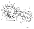
- a pair of pliers contains the following components: a first working jaw 1, a first gripper handle 2, a second working jaw 3, a second gripper handle 4, V-shaped spring plates 5 and 6 and a resilient connecting member 7, for example a compression spring.
- the first working jaws 1 and the first forceps handle 2 are integrally connected to each other and consist of a total of two mutually parallel sheets 8 and 9, which are held by a plurality of spacers 10, 11 and 12 at a distance from each other.
- the spacers 10, 11 and 12 each have a passage opening through which a bolt 13, 14 and 15 passes, which holds the sheets 8 and 9 together.
- the first working jaw 1 has a recess pointing in the direction of the second working jaw 3 for forming a forceps jaw 16 together with a corresponding recess in the second working jaw 3.
- the second forceps handle 4 is constructed in the same way as the first forceps handle 2. It also consists of two parallel plates 17 and 18, which are held by spacers 19 and 20 at a distance from each other. These spacers 19 and 20 are also hollow and receive bolts 21 and 22 which hold the sheets 17 and 18 together. In this case, the distance between the sheets 17 and 18 from one another corresponds to the spacing of the sheets 8 and 9.
- the plates 17 and 18 are extended in their plane. They take there a rear portion 23 of the second working jaw 3 between them.
- This rear portion 23 of the second working jaw 3 is pivotally mounted on the front portion of the second forceps handle 4 and arranged for this purpose rotatable about an axis 24 which is held by the sheets 17 and 18 and passes through an opening 46 in the rear portion 23.
- the second working jaw 3 As will be described in more detail with reference to Figure 2, belonging to the second working jaw 3 two lateral jaw plates 25 and 26, which laterally nestle against a central node element 27 of the second working jaw 3 and are held at a distance from each other, which is also the distance of Sheets 17, 18 and 8, 9 corresponds to each other. For cohesion of the jaw plates 25 and 26 with the central node element 27 are screws 28 and bolts 29, which enforce these elements.
- the second working jaw 3 is rotatably mounted on the first working jaw 1 via a pivot axis 30.
- pivot axis 30 On both outer and the second working jaws 3 outwardly projecting ends of the pivot axis 30 is seated one end of the V-shaped spring plates 5 and 6, the other end is attached in each case via a bolt 31 at the upper region of the upper working jaw 1, ie above the Pivot axis 30.
- the pivot axis 30 fits in a Recess 32 of the second working jaw 3 and on the other hand is in slots 33 which are located respectively in the sheets 8 and 9 of the first working jaw 1, wherein the longitudinal direction of the slots 33 is at least approximately perpendicular to the forceps longitudinal direction.
- the resilient connecting member 7 consists of two mutually parallel spring plates 34 and 35 and is articulated at its lower end in the front region of the second forceps handle 4, to which it is pivotable about an axis 36 which passes through the connecting member 7 and the sheets 17 and 18th is held.
- the axis 36 is shifted relative to the axis 24 to the rear end of the tong.
- the other end of the resilient connecting member 7 is pivotable on an eccentrically mounted shaft 37 and mounted on it on the first handle 2.
- the eccentrically mounted shaft 37 is displaced with respect to the axis 36 to the rear end of the pliers.
- axle stub 38 which are rotatably mounted in the sheets 8 and 9.
- FIG. 2 shows the more detailed construction of the pliers according to FIG. 1. The same elements are again provided with the same reference numerals and will not be described again.
- the central region of Figure 2 shows the more detailed structure of the lower working jaw 3.
- the central node element 27 consists in the present case of a middle plate 41, which consists for example of plastic, and two adjacent to both sides of the middle plate 41 outer plates 42nd and 43, which are made of steel. All plates 41, 42 and 43 form an approximately U-shaped component, the free legs facing the rear end of the pliers.
- the two jaw plates 25 and 26 are mounted laterally in the region of the base and the lower leg, wherein the sheets are held together by the screw 28.
- As an anti-rotation serve the bolts 29, which are held by retaining rings.
- the jaw plates 25 and 26 protrude from the bottom of the U-shaped component and together with the front portions of the sheets 8 and 9, the forceps jaw 16.
- both the jaw plates 25 and 26 and the sheets 8 and 9 bevelled so that their opposite edges to the rear tong end away from each other. From the clamping jaw plates 25, 26 and the sheets 8 and 9 carried machining elements in the forceps jaw 16 can therefore tilt according to the closed position of the pliers, namely about respective tilting axes which are passed through openings 44 and 45 of the working jaws 1 and 3 and the processing elements in Hold pliers mouth 16.
- the U-shaped component shown in the middle region of FIG. 2 has, in its remaining region of the base, the passage opening 32, which serves for the suitable accommodation of the pivot axis 30.
- This pivot axis 30 is, as already mentioned, taken up by the oblong holes 33, so that in this way the second working jaw 3 is pivotally mounted on the first working jaw 1.
- the free end of the lower leg of the U-shaped component in the central region of Figure 2 forms the said rear portion 23 of the second working jaw 3 and is provided there with a through-hole 46 through which the axis 24 passes to thus the second handle 4 to store the second working jaw 3 pivotally.
- the upper leg of the U-shaped component 27 in Figure 2 has on its inside a toothing 47 which is coaxial with the through hole 46.
- a pawl 48 In the toothing 47 engages a pawl 48, which can be seen in Figures 3 and 4.
- This pawl 48 may also be a pair of pawls, one of which engages in a toothing 47 on one of the plates 42, 43.
- the pawl 48 is pivotally mounted in the front region of the lower pliers handle 4 about an axis 49, which can be seen in the lower part of Figure 2.
- the axis 49 is movable on a path concentric with the axis 24.
- the length of the pawl 48 is greater than the distance between the axis 49 and teeth 47.
- Semicircular openings 50 coaxial with the axis 49 in the sheets 17 and 18 serve for manual actuation of the pawl 48 to bring it out of engagement with the teeth 47.
- In the front region of the second forceps handle 4 in Figure 2 are still through holes 51 and 52 can be seen in the sheets 17 and 18, which serve to receive the axes 24 and 36 in Figure 1.
- the pawl 48 can rotate about the axis 49 and held by a spring 57 which is fixed in the lower region of the connecting member 7 in a zero position, which is actually achieved only when the pawl 48 is disengaged from the toothing 47. If the pawl 48 engages with the toothing 47, it can give way, for example, when the forceps jaw 16 closes and not in the opposite direction. In order to bring the pawl 48 out of engagement with the teeth 47 in an intermediate position of the pliers handles 2, 4, connected to the pawl approach 58 can be manually operated through the slots 50 therethrough. The pawl 48 itself is practically in the interior of the central node element 27, so that no additional space inside the pliers is needed for this ratchet mechanism of teeth 47 and pawl 48. The pliers can therefore be reduced relatively compact.
- FIG. 3 shows the pliers in the fully opened state.
- both the total as a tension spring to be designated spring plates 5 and 6 are relieved and the connecting member. 7
- the force in the forceps jaw 16 is determined both by the spring plates 5 and 6 and by the connecting member 7.
- the characteristics of all springs add up and lead to a predetermined force curve in the forceps jaw 16 in response to the closing movement of the working jaws 1 and 3.
- the force curve in the forceps jaw is here essentially defined by the spring plates 5 and 6, with increasing closing movement of the forceps handles the pivot axis 30 is moved away in Figure 3 or from the first working jaw 1.
- the force curve in the forceps jaw can be generated by the V-shaped spring plates 5 and 6 for this short working path, with only a relatively small support by the connecting member 7 takes place.
- the working path then begins after the tool elements have come into contact with the object to be processed.
- These spring plates can be bent only over the length of the slot 33, since only in this case ensures that they actually deliver the desired force curve. A bending of the spring plates 5 and 6 beyond would lead to a distortion of the force curve, since then change their elastic properties in an undefined manner.
- FIG. 4 shows the pliers in the fully closed state.
- all the spring elements 5, 6, 7 still charged and the pawl 48 out of engagement with the teeth 47, so that the forceps can be opened again, if in the forceps jaw 16 is a machined (not shown) object.
- the connecting member 7 ensures due to its chosen spring characteristic that when a given forceps jaw limit force is exceeded due to the then incipient behavior of the connecting member 7, the forceps handles can still be closed, so that then the pliers can be opened again.
- FIG. 5 once again shows the forceps according to the invention in a perspective view, now supplemented with grip shells 59 and 60 arranged on the metal sheets 8, 9 and 17, 18.
- the inventive pliers can be present as a single tool or as an integral part of a machine tool.
- the forceps handles 2, 4 may be formed so that the forceps can be connected via their forceps handles with a machine for forceps drive.
- the pliers but also in whole or in parts may be a permanent part of a machine tool for driving the pliers.
- At least the forceps handles of the forceps can be parts of this machine tool.
- the pliers handles could be coupled to the rest of the pliers parts, which could be the pliers handles combine with each other different pliers parts of the type described above. One could thus take into account different dimensions of the material to be processed.
- FIG. 4 for example, a machine M connected to the forceps handles 2, 4 is shown with dashed lines.
- the machine M is practically simulated the movement of the pliers handles 2, 4 for driving the pliers.
Landscapes
- Engineering & Computer Science (AREA)
- Mechanical Engineering (AREA)
- Gripping Jigs, Holding Jigs, And Positioning Jigs (AREA)
- Crystals, And After-Treatments Of Crystals (AREA)
- Manipulator (AREA)
- Surgical Instruments (AREA)
- Scissors And Nippers (AREA)
Abstract
Description
Die Erfindung betrifft eine Zange gemäß dem Oberbegriff des Schutzanspruchs 1.The invention relates to a pair of pliers according to the preamble of
Eine derartige Zange ist bereits aus der
Bei dieser Zange dient das Verbindungsglied zur Verbesserung der Elastizität der Zange.With this pliers, the connecting link serves to improve the elasticity of the pliers.
Weitere Zangen der genannten Art sind aus der
Der Erfindung liegt die Aufgabe zugrunde, eine Zange der eingangs genannten Art so weiterzubilden, daß sich mit ihr bessere Arbeitsergebnisse erzielen lassen. Insbesondere soll es möglich sein, eine bessere Selbsteinstellung des Kraftverlaufs im Zangenmaul in Abhängigkeit der Schließbewegung der Arbeitsbacken zu ermöglichen, und zwar auch im Hinblick auf unterschiedlich große und im Zangenmaul zu bearbeitende Gegenstände.The invention has the object of developing a pair of pliers of the type mentioned so that can be achieved with her better work results. In particular, it should be possible to allow a better self-adjustment of the force curve in the forceps jaw in response to the closing movement of the working jaws, even with regard to different sized and to be processed in the forceps jaws objects.
Die Lösung der gestellten Aufgabe besteht darin, daß die Schwenkachse an einem der Arbeitsbacken befestigt ist und sich im anderen Arbeitsbacken ein Langloch zur Aufnahme der Schwenkachse befindet, dessen Längsrichtung in der Zangenebene und wenigstens annähernd senkrecht zur Zangenlängsrichtung verläuft, und daß eine Zugfeder mit einem Ende an der Schwenkachse und mit ihrem anderen Ende an dem das Langloch aufweisenden Arbeitsbacken befestigt ist, wobei zur Erzeugung eines gewünschten Kraftverlaufs im Zangenmaul die Zugfeder und das Verbindungsglied so ausgebildet sind, daß über einen durch die Länge des Langlochs begrenzten Schließweg der Arbeitsbacken die erforderliche Maulkraft durch die Zugfeder und das Verbindungsglied aufgebracht wird und über einen sich daran anschließenden Schließweg der Arbeitsbacken allein durch das Verbindungsglied bereitgestellt wird.The solution of the problem is that the pivot axis is attached to one of the working jaws and in the other working jaws a slot for receiving the pivot axis is located, whose longitudinal direction in the forceps plane and at least approximately perpendicular to the forceps longitudinal direction, and that a tension spring is attached at one end to the pivot axis and with its other end to the slot having working jaws, wherein to produce a desired Force curve in the forceps jaw, the tension spring and the connecting member are formed so that over a limited by the length of the slot closing the working jaws the required mouth force is applied by the tension spring and the connecting member and is provided via an adjoining closing of the working jaws alone by the connecting member ,
Durch die Kombination von Zugfeder und federndem Verbindungsglied wird es erfindungsgemäß möglich, den Kraftverlauf im Zangenmaul in Abhängigkeit der Schließbewegung der Arbeitsbacken sehr fein an gewünschte Verhältnisse anzupassen, auch für den Fall, daß unterschiedlich große Gegenstände im Zangenmaul zu bearbeiten sind, so daß sich von daher bessere Arbeitsergebnisse erzielen lassen. Dies gilt insbesondere dann, wenn es sich bei der Zange um eine Crimpzange handelt, mit der zum Beispiel Aderendhülsen oder andere Kontaktelemente auf Leitungsenden aufgepreßt werden sollen. Der Kraftverlauf im Zangenmaul in Abhängigkeit der Schließbewegung der Arbeitsbacken wird dadurch eingestellt, daß die jeweiligen Federkennlinien von Zugfeder und Verbindungsglied miteinander kombiniert werden.The combination of tension spring and resilient connecting member, it is inventively possible to adjust the force curve in the forceps jaw in response to the closing movement of the working jaws very fine to desired conditions, even in the event that different sized objects are to be processed in the forceps jaw, so that from therefore achieve better work results. This is especially true when it is the pliers to a crimping tool with which, for example, wire end ferrules or other contact elements to be pressed onto cable ends. The force curve in the forceps jaw in response to the closing movement of the working jaws is adjusted by the fact that the respective spring characteristics of tension spring and link are combined.
Wenn die ansonsten zur genauen Einstellung der Maulkraft herangezogene Zugfeder bei zu großen Maulkräften oder zu langen Schließwegen der Arbeitsbacken überdehnt werden würde, wird die Zugfeder ausgeschaltet und die erforderliche Maulkraft wird über einen weiteren Schließweg der Arbeitsbacken dann nur noch vom Verbindungsglied aufgebracht. Dadurch läßt sich auch über relativ große Schließwege der Arbeitsbacken die Erzeugung eines gewünschten Kraftverlaufs im Zangenmaul sicherstellen.If the tension spring otherwise used for the exact adjustment of the mouth force would be overstretched if the mouth jaws or the closing jaws of the working jaws are too large, the tension spring is switched off and the required jaw force is then applied only by the connecting link via a further closing path of the working jaws. As a result, the production can be over relatively large closing paths of the working jaws ensure a desired force curve in the forceps mouth.
Nach einer Ausgestaltung der Erfindung können die Federkennlinien von Zugfeder und Verbindungsglied so aneinander angepaßt sein, daß bei Erreichen des durch die Länge des Langlochs begrenzten Schließwegs der Arbeitsbacken und weiterer Schließbewegung ein möglichst sprungfreier Kraftverlauf im Zangenmaul erzielt wird.According to one embodiment of the invention, the spring characteristics of tension spring and connecting member can be adapted to each other so that when reaching the limited by the length of the slot closing path of the working jaws and further closing movement a jump-free force curve in the forceps jaw is achieved.
Dadurch läßt sich ein gleichmäßigerer Verformungsvorgang im Zangenmaul durchführen und somit ein noch besseres Arbeitsergebnis erhalten. Diese Maßnahme ermöglicht ein besonders günstiges ergonomisches Handhaben der Zange.This makes it possible to perform a more uniform deformation process in the forceps jaw and thus obtain an even better work result. This measure allows a particularly favorable ergonomic handling of the forceps.
In Ausgestaltung der Erfindung kann das Verbindungsglied so ausgebildet sein, daß es nach Überschreiten einer vorbestimmten Zangenmaul-Grenzkraft stark nachgibt. Dadurch wird eine Beschädigung insbesondere größerer im Zangenmaul zu bearbeitender Teile beim weiteren Schließen der Zangengriffe vermieden, und es wird die Möglichkeit geschaffen, eine üblicherweise mit der Zange zusammenarbeitende Sperrklinke außer Eingriff mit einer Zahnreihe zu bringen, um das Zangenmaul öffnen zu können.In an embodiment of the invention, the connecting member may be formed so that it gives way after exceeding a predetermined forceps jaw limit force. As a result, damage especially larger parts to be machined in the forceps jaw during further closing of the forceps handles is avoided, and it is possible to bring a commonly cooperating with the forceps pawl out of engagement with a row of teeth to open the forceps jaw.
In noch weiterer Ausgestaltung der Erfindung ist die Schwenkachse vorzugsweise am zweiten Arbeitsbacken befestigt, wobei sich das Langloch im ersten Arbeitsbacken befindet. Dadurch läßt sich die Zugfeder am ersten und unbeweglichen Arbeitsbacken befestigen, so daß sie im Betrieb der Zange nicht verschwenkt wird und sich daher ihre Kennlinie nicht verfälscht.In a further embodiment of the invention, the pivot axis is preferably attached to the second working jaws, wherein the slot is located in the first working jaws. As a result, the tension spring can be fixed to the first and immovable working jaws, so that it is not pivoted during operation of the forceps and therefore does not distort their characteristic.
Die Zugfeder selbst kann jede geeignete Form aufweisen, vorzugsweise aber auch zum Beispiel als V-förmige, U-förmige oder Ω-förmige Blattfeder ausgebildet sein. Bei Federn dieser Art läßt sich die gewünschte Kennlinie in besonders einfacher Weise durch Wahl der entsprechenden Abmessungen bzw. Materialstärken einstellen.The tension spring itself may have any suitable shape, but preferably also be formed, for example, as a V-shaped, U-shaped or Ω-shaped leaf spring. In springs of this type, the desired characteristic can be adjusted in a particularly simple manner by selecting the appropriate dimensions or material thicknesses.
Als Verbindungsglied kann vorzugsweise ein flachplattenartiges Federblech zum Einsatz kommen oder ein Paket aus derartigen Federblechen, wobei sich auch bei diesen Blechen die Federkennlinie durch entsprechende Materialabmessungen und Materialstärken leicht vorgeben lassen.As a connecting member may preferably be a flat plate-like spring plate are used or a package of such feather plates, which can be easily predefined by appropriate material dimensions and material thicknesses in these sheets, the spring characteristic.
Ein Ausführungsbeispiel der Erfindung wird nachfolgend unter Bezugnahme auf die Zeichnung im einzelnen erläutert. Es zeigen:
-
Figur 1 eine perspektivische Ansicht der erfindungsgemäßen Zange ohne Griffschalen; - Figur 2 eine Explosionsdarstellung der Zange nach
Figur 1; -
Figur 3 eine Seitenansicht der Zange nachFigur 1 in geöffnetem Zustand bei abgenommenen Seitenblechen, jedoch mit eingesetzter Ω-Feder; -
Figur 4 eine Seitenansicht der Zange nachFigur 1 in geschlossenem Zustand bei abgenommenen Seitenblechen, jedoch mit eingesetzter Ω-Feder; und -
Figur 5 eine perspektivische Ansicht der erfindungsgemäßen Zange mit Griffschalen.
- Figure 1 is a perspective view of the pliers according to the invention without handle shells;
- Figure 2 is an exploded view of the pliers of Figure 1;
- Figure 3 is a side view of the pliers of Figure 1 in the open state with removed side plates, but with inserted Ω spring;
- Figure 4 is a side view of the pliers of Figure 1 in the closed state with removed side plates, but with inserted Ω spring; and
- Figure 5 is a perspective view of the forceps according to the invention with handles.
Entsprechend der Figur 1 enthält eine erfindungsgemäße Zange folgende Baugruppen: einen ersten Arbeitsbacken 1, einen ersten Zangengriff 2, einen zweiten Arbeitsbacken 3, einen zweiten Zangengriff 4, V-förmig ausgebildete Federbleche 5 und 6 sowie ein federndes Verbindungsglied 7, zum Beispiel eine Druckfeder.According to FIG. 1, a pair of pliers according to the invention contains the following components: a first working
Der erste Arbeitsbacken 1 und der erste Zangengriff 2 sind einstückig miteinander verbunden und bestehen insgesamt aus zwei parallel zueinander liegenden Blechen 8 und 9, die über mehrere Distanzstücke 10, 11 und 12 auf Abstand zueinander gehalten sind. Die Distanzstücke 10, 11 und 12 weisen jeweils eine Durchgangsöffnung auf, durch die ein Bolzen 13, 14 und 15 hindurchläuft, der die Bleche 8 und 9 zusammenhält.The first working
Im vorderen Bereich weist der erste Arbeitsbacken 1 eine in Richtung zum zweiten Arbeitsbacken 3 weisende Ausnehmung zur Bildung eines Zangenmauls 16 zusammen mit einer entsprechenden Ausnehmung im zweiten Arbeitsbacken 3 auf.In the front region, the first working
Der zweite Zangengriff 4 ist entsprechend wie der erste Zangengriff 2 aufgebaut. Auch er besteht aus zwei parallelen Blechen 17 und 18, die über Distanzstücke 19 und 20 auf Abstand zueinander gehalten sind. Diese Distanzstücke 19 und 20 sind ebenfalls hohl und nehmen Bolzen 21 und 22 auf, die die Bleche 17 und 18 zusammenhalten. Dabei entspricht der Abstand der Bleche 17 und 18 voneinander dem Abstand der Bleche 8 und 9.The
In ihrem zum Zangenmaul 16 weisenden vorderen Bereich sind die Bleche 17 und 18 in ihrer Ebene erweitert. Sie nehmen dort einen hinteren Abschnitt 23 des zweiten Arbeitsbackens 3 zwischen sich auf. Dieser hintere Abschnitt 23 des zweiten Arbeitsbackens 3 ist schwenkbar am vorderen Bereich des zweiten Zangengriffs 4 gelagert und zu diesem Zweck drehbar um eine Achse 24 angeordnet, die von den Blechen 17 und 18 gehalten wird und eine Öffnung 46 im hinteren Abschnitt 23 durchsetzt.In her pointing to the
Wie unter Bezugnahme auf die Figur 2 noch genauer beschrieben wird, gehören zum zweiten Arbeitsbacken 3 zwei seitliche Klemmbackenbleche 25 und 26, die sich an ein zentrales Knotenelement 27 des zweiten Arbeitsbackens 3 seitlich anschmiegen und in einem Abstand voneinander gehalten sind, der ebenfalls dem Abstand der Bleche 17, 18 bzw. 8, 9 voneinander entspricht. Zum Zusammenhalt der Klemmbackenbleche 25 und 26 mit dem zentralen Knotenelement 27 dienen Schrauben 28 und Bolzen 29, die diese Elemente durchsetzen. Über eine Schwenkachse 30 ist der zweite Arbeitsbacken 3, wie unter Bezugnahme auf die Figur 2 noch ausgeführt werden wird, am ersten Arbeitsbacken 1 drehbar gelagert. Auf beiden äußeren und den zweiten Arbeitsbacken 3 nach außen überragenden Enden der Schwenkachse 30 sitzt jeweils ein Ende der V-förmig ausgebildeten Federbleche 5 und 6, deren anderes Ende jeweils über einen Bolzen 31 am oberen Bereich des oberen Arbeitsbackens 1 befestigt ist, also oberhalb der Schwenkachse 30. Dabei sitzt die Schwenkachse 30 passend in einer Ausnehmung 32 des zweiten Arbeitsbackens 3 und liegt andererseits in Langlöchern 33, die sich jeweils in den Blechen 8 und 9 des ersten Arbeitsbackens 1 befinden, wobei die Längsrichtung der Langlöcher 33 wenigstens annähernd senkrecht zur Zangenlängsrichtung steht.As will be described in more detail with reference to Figure 2, belonging to the second working
Das federnde Verbindungsglied 7 besteht aus zwei parallel zueinander liegenden Federblechen 34 und 35 und ist mit seinem unteren Ende im vorderen Bereich des zweiten Zangengriffs 4 angelenkt, wozu es um eine Achse 36 schwenkbar ist, die das Verbindungsglied 7 durchsetzt und von den Blechen 17 und 18 gehalten wird. Die Achse 36 ist gegenüber der Achse 24 zum hinteren Zangenende hin verschoben. Das andere Ende des federnden Verbindungsglieds 7 ist auf einer exzentrisch gelagerten Achse 37 schwenkbar und über sie am ersten Handgriff 2 gelagert. Dabei ist die exzentrisch gelagerte Achse 37 gegenüber der Achse 36 zum hinteren Ende der Zange hin verschoben. Zur exzentrischen Lagerung der Achse 37 dienen beidseitige Achsstummel 38, die drehbar in den Blechen 8 und 9 gelagert sind. Auf einem dieser Achsstummel 38 sitzt eine Stellscheibe 39 mit randseitigen Ausnehmungen, die zur Arretierung der Winkelstellung der Stellscheibe 39 mittels einer Schraube 40 dienen. Durch Einstellung der Stellscheibe 39 kann über die exzentrische Lagerung des Verbindungsglieds 7 dessen Länge verändert und damit die Stellung der Arbeitsbacken 1 und 3 zueinander justiert werden.The resilient connecting member 7 consists of two mutually parallel spring plates 34 and 35 and is articulated at its lower end in the front region of the
Die Figur 2 zeigt den genaueren Aufbau der Zange nach Figur 1. Gleiche Elemente sind wieder mit den gleichen Bezugszeichen versehen und werden nicht nochmals beschrieben.FIG. 2 shows the more detailed construction of the pliers according to FIG. 1. The same elements are again provided with the same reference numerals and will not be described again.
Im oberen Teil der Figur 2 sind zunächst die Langlöcher 33 gut zu erkennen, deren Längsrichtung senkrecht zur Zangenlängsrichtung verläuft. Im Abstand oberhalb der Langlöcher 33 befinden sich jeweils die Bolzen 31 an der Außenseite der Bleche 8 und 9, die zur Aufnahme des einen Endes der V-förmigen Federbleche 5 und 6 dienen. Das jeweils andere Ende der Federbleche 5 und 6 ist geschwungen ausgeführt und nimmt die in Figur 1 gezeigte Schwenkachse 30 passend auf.In the upper part of Figure 2, the
Der mittlere Bereich der Figur 2 zeigt den genaueren Aufbau des unteren Arbeitsbackens 3. Das zentrale Knotenelement 27 besteht im vorliegenden Fall aus einer mittleren Platte 41, die zum Beispiel aus Kunststoff besteht, sowie aus zwei an beiden Seiten der mittleren Platte 41 anliegenden äußeren Platten 42 und 43, die etwa aus Stahl hergestellt sind. Sämtliche Platten 41, 42 und 43 bilden ein etwa U-förmiges Bauteil, dessen freie Schenkel zum hinteren Zangenende weisen. An diesem Bauteil sind im Bereich der Basis und des unteren Schenkels die beiden Klemmbackenbleche 25 und 26 seitlich angebracht, wobei die Bleche durch die Schraube 28 zusammengehalten werden. Als Verdrehsicherung dienen die Bolzen 29, die über Sicherungsringe gehalten werden. Die Klemmbackenbleche 25 und 26 stehen vom Boden des U-förmigen Bauteils ab und bilden zusammen mit den vorderen Abschnitten der Bleche 8 und 9 das Zangenmaul 16. Im hinteren Bereich des Zangenmauls 16 sind sowohl die Klemmbackenbleche 25 und 26 als auch die Bleche 8 und 9 abgeschrägt, so daß sich ihre gegenüberliegenden Kanten zum hinteren Zangenende hin voneinander entfernen. Von den Klemmbackenblechen 25, 26 bzw. den Blechen 8 und 9 getragene Bearbeitungselemente im Zangenmaul 16 können daher entsprechend der Schließstellung der Zange kippen, und zwar um jeweilige Kippachsen, die durch Öffnungen 44 und 45 der Arbeitsbacken 1 und 3 hindurchgeführt sind und die Bearbeitungselemente im Zangenmaul 16 halten.The central region of Figure 2 shows the more detailed structure of the lower working
Das im mittleren Bereich der Figur 2 gezeigte U-förmige Bauteil weist in seinem verbleibenden Bereich der Basis die Durchgangsöffnung 32 auf, die zur passenden Aufnahme der Schwenkachse 30 dient. Diese Schwenkachse 30 wird, wie bereits erwähnt, von den Langlöchern 33 aufgenommen, so daß auf diese Weise der zweite Arbeitsbacken 3 am ersten Arbeitsbacken 1 schwenkbar gelagert wird. Das freie Ende des unteren Schenkels des U-förmigen Bauteils im mittleren Bereich der Figur 2 bildet den genannten hinteren Abschnitt 23 des zweiten Arbeitsbackens 3 und ist dort mit einer Durchgangsbohrung 46 versehen, durch die die Achse 24 hindurchläuft, um auf diese Weise den zweiten Handgriff 4 am zweiten Arbeitsbacken 3 schwenkbar zu lagern.The U-shaped component shown in the middle region of FIG. 2 has, in its remaining region of the base, the passage opening 32, which serves for the suitable accommodation of the
Der obere Schenkel des U-förmigen Bauteils 27 in Figur 2 weist an seiner Innenseite eine Verzahnung 47 auf, die koaxial zur Durchgangsbohrung 46 liegt. In die Verzahnung 47 greift eine Sperrklinke 48 ein, die in den Figuren 3 und 4 zu erkennen ist. Diese Sperrklinke 48 kann auch ein Sperrklinkenpaar sein, von denen jeweils eine in eine Verzahnung 47 an einer der Platten 42, 43 eingreift. Durch sie wird erreicht, daß die Zange erst dann wieder geöffnet werden kann, nachdem die Zangengriffe ihre Schließstellung erreicht haben. Die Sperrklinke 48 ist im vorderen Bereich des unteren Zangengriffs 4 um eine Achse 49 schwenkbar gelagert, die im unteren Teil der Figur 2 zu sehen ist. Die Achse 49 ist auf einer Bahn konzentrisch zur Achse 24 bewegbar. Daher ist die Länge der Sperrklinke 48 größer als der Abstand zwischen Achse 49 und Verzahnung 47. Halbkreisförmige Öffnungen 50 koaxial zur Achse 49 in den Blechen 17 und 18 dienen zur manuellen Betätigung der Sperrklinke 48, um sie außer Eingriff mit der Verzahnung 47 zu bringen. Im vorderen Bereich des zweiten Zangengriffs 4 in Figur 2 sind noch Durchgangsöffnungen 51 und 52 in den Blechen 17 und 18 zu erkennen, die zur Aufnahme der Achsen 24 und 36 in Figur 1 dienen.The upper leg of the
An der Außenseite des oberen Schenkels des zentralen Knotenelements 27 in Figur 2 sind noch hakenförmige Ansätze 53 am hinteren Ende der Platten 42 und 43 zu sehen. Diese Ansätze 53, die auch ergänzt werden können, um Durchgangsöffnungen zu erhalten, dienen zur Aufnahme einer Achse, an welcher ein Ende einer in den Figuren 3 und 4 gezeigten Zugfeder befestigt wird, die das Bezugszeichen 54 trägt. Das andere Ende dieser Zugfeder 54 ist im oberen Bereich des ersten Arbeitsbackens 1 an einer Achse 55 befestigt. Die Zugfeder 54 dient dazu, bei Erreichen der Schließstellung der Zangengriffe 2, 4 die Zange automatisch wieder zu öffnen. Die Schließstellung der Zangengriffe ist erreicht, wenn die Sperrklinke 48 außer Eingriff mit der Verzahnung 47 kommt. Die oberen Anschläge 56 am zweiten Griffelement 4 schlagen dann später gegen die unteren Kanten des ersten Griffelements 2.On the outside of the upper leg of the
Bezüglich der Figuren 3 und 4 sei noch erwähnt, daß sich die Sperrklinke 48 um die Achse 49 drehen kann und mittels einer Feder 57, die im unteren Bereich des Verbindungsglieds 7 befestigt ist, in einer Nullstellung gehalten wird, die nur dann tatsächlich erreicht wird, wenn die Sperrklinke 48 außer Eingriff mit der Verzahnung 47 ist. Ist die Sperrklinke 48 in Eingriff mit der Verzahnung 47, kann sie zum Beispiel bei sich schließendem Zangenmaul 16 nachgeben und nicht in umgekehrter Richtung. Um die Sperrklinke 48 außer Eingriff mit der Verzahnung 47 in einer Zwischenstellung der Zangengriffe 2, 4 zu bringen, kann ein mit der Sperrklinke verbundener Ansatz 58 durch die Langlöcher 50 hindurch manuell betätigt werden. Die Sperrklinke 48 selbst liegt praktisch im Inneren des zentralen Knotenelements 27, so daß für diesen Ratschenmechanismus aus Verzahnung 47 und Sperrklinke 48 kein zusätzlicher Platz innerhalb der Zange benötigt wird. Die Zange kann daher relativ kompakt abgebaut werden.With reference to Figures 3 and 4 it should be mentioned that the
Nachfolgend soll die Funktionsweise der Zange unter Bezugnahme auf die Figuren 3 und 4 näher erläutert werden.Below, the operation of the pliers with reference to Figures 3 and 4 will be explained in more detail.
Die Figur 3 zeigt die Zange in vollständig geöffnetem Zustand. Hier sind sowohl die insgesamt auch als Zugfeder zu bezeichnenden Federbleche 5 und 6 entlastet als auch das Verbindungsglied 7.FIG. 3 shows the pliers in the fully opened state. Here, both the total as a tension spring to be designated
Werden die Zangengriffe 2 und 4 bzw. Bleche 9 und 18 in Figur 3 aufeinander zu bewegt, so wird die Kraft im Zangenmaul 16 sowohl durch die Federbleche 5 und 6 als auch durch das Verbindungsglied 7 bestimmt. Die Kennlinien aller Federn addieren sich und führen zu einem vorbestimmten Kraftverlauf im Zangenmaul 16 in Abhängigkeit von der Schließbewegung der Arbeitsbacken 1 und 3. Der Kraftverlauf im Zangenmaul wird hier im wesentlichen durch die Federbleche 5 und 6 definiert, wobei mit zunehmender Schließbewegung der Zangengriffe die Schwenkachse 30 nach unten in Figur 3 bzw. vom ersten Arbeitsbacken 1 wegbewegt wird.If the forceps handles 2 and 4 or
Befindet sich ein relativ kleiner zu bearbeitender Gegenstand im Zangenmaul 16 bzw. zwischen dort angeordneten Werkzeugelementen und ist demzufolge nur ein relativ kurzer Arbeitsweg der Arbeitsbacken 1 und 3 erforderlich, so kann für diesen kurzen Arbeitsweg der Kraftverlauf im Zangenmaul im wesentlichen durch die V-förmigen Federbleche 5 und 6 erzeugt werden, wobei nur eine relativ geringe Unterstützung durch das Verbindungsglied 7 erfolgt. Der Arbeitsweg beginnt dann, nachdem die Werkzeugelemente in Kontakt mit dem zu bearbeitenden Gegenstand gekommen sind. Diese Federbleche lassen sich nur über die Länge des Langlochs 33 verbiegen, da nur in diesem Fall gewährleistet ist, daß sie den gewünschten Kraftverlauf tatsächlich liefern. Eine Verbiegung der Federbleche 5 und 6 darüberhinaus würde zu einer Verfälschung des Kraftverlaufs führen, da sich dann ihre elastischen Eigenschaften in undefinierter Weise ändern.Is there a relatively small object to be machined in the
Sind dagegen im Zangenmaul zu bearbeitende Gegenstände über einen relativ langen Arbeitsweg zu verformen, über den die V-förmigen Federbleche 5, 6 den gewünschten Kraftverlauf nicht mehr liefern können, so wird über den ersten Teil des Weges entsprechend der Länge des Langlochs der Kraftverlauf im Zangenmaul 16 im wesentlichen durch die V-förmigen Federbleche bestimmt, wobei er vom Verbindungsglied 7 mit beeinflußt wird, während nach Durchlaufen des für die V-förmigen Federbleche 5 und 6 zulässigen Weges der Kraftverlauf im Zangenmaul für den weiteren Weg im wesentlichen nur noch durch die Federeigenschaften des Verbindungsglieds 7 bestimmt wird. Auf diese Weise wird sichergestellt, daß über den Gesamtweg, über den das zu bearbeitende Element im Zangenmaul 16 bearbeitet bzw. verpreßt werden muß, der gewünschte Kraftverlauf auch tatsächlich zur Verfügung gestellt wird.On the other hand, if objects to be machined in the forceps jaw are to be deformed over a relatively long working path over which the V-shaped
Die Figur 4 zeigt die Zange in vollständig geschlossenem Zustand. Hier sind alle Federelemente 5, 6, 7 noch belastet und die Sperrklinke 48 außer Eingriff mit der Verzahnung 47, so daß die Zange sich wieder öffnen läßt, sofern sich im Zangenmaul 16 ein bearbeiteter (nicht dargestellter) Gegenstand befindet.FIG. 4 shows the pliers in the fully closed state. Here are all the
Sollte der Fall auftreten, daß die Zangengriffe 2, 4 noch nicht geschlossen sind, auch nachdem die Arbeitsbacken 1, 3 einen Schließweg durchlaufen haben, der über den die V-förmigen Federbleche vorgesehenen Schließweg hinausgeht, so sorgt das Verbindungsglied 7 aufgrund seiner gewählten Federkennlinie dafür, daß bei Überschreiten einer vorgesehenen Zangenmaul-Grenzkraft aufgrund des dann einsetzenden nachgiebigen Verhaltens des Verbindungsglieds 7 die Zangengriffe dennoch geschlossen werden können, so daß sich die Zange dann wieder öffnen läßt.If the case occurs that the forceps handles 2, 4 are not yet closed, even after the working
Die Figur 5 zeigt nochmals die erfindungsgemäße Zangen in perspektivischer Ansicht, jetzt ergänzt mit auf den Blechen 8, 9 bzw. 17, 18 angeordneten Griffschalen 59 und 60.FIG. 5 once again shows the forceps according to the invention in a perspective view, now supplemented with
Die erfndungsgemäße Zange kann als Einzelwerkzeug an sich vorliegen oder als integrierter Bestandteil einer Werkzeugmaschine. Im Falle eines Einzelwerkzeugs können nach einer Ausgestaltung der Erfindung die Zangengriffe 2, 4 so ausgebildet sein, daß die Zange über ihre Zangengriffe auch mit einer Maschine zum Zangenantrieb verbindbar ist. Somit ergeben sich für die Zange mehrere Anwendungsmöglichkeiten. Sie läßt sich dadurch manuell betätigen oder maschinengesteuert antreiben, um periodisch wiederkehrende Arbeiten über einen längeren Zeitraum durchführen zu können. Andererseits kann die Zange aber auch insgesamt oder in Teilen ständiger Bestandteil einer Werkzeugmaschine zum Antrieb der Zange sein. Dabei können wenigstens die Zangengriffe der Zange Teile dieser Werkzeugmaschine sein. In diesem Fall könnten die Zangengriffe mit den restlichen Zangenteilen kuppelbar sein, wodurch sich die Zangengriffe mit jeweils unterschiedlichen restlichen Zangenteilen der zuvor beschriebenen Art verbinden ließen. Man könnte somit unterschiedlichen Dimensionierungen des zu bearbeitenden Guts Rechnung tragen.The inventive pliers can be present as a single tool or as an integral part of a machine tool. In the case of a single tool, according to one embodiment of the invention, the forceps handles 2, 4 may be formed so that the forceps can be connected via their forceps handles with a machine for forceps drive. Thus arise for the pliers several applications. It can thereby be operated manually or driven by a machine, in order to carry out periodically recurring work over a longer period of time. On the other hand, the pliers but also in whole or in parts may be a permanent part of a machine tool for driving the pliers. At least the forceps handles of the forceps can be parts of this machine tool. In this case, the pliers handles could be coupled to the rest of the pliers parts, which could be the pliers handles combine with each other different pliers parts of the type described above. One could thus take into account different dimensions of the material to be processed.
In Figur 4 ist zum Beispiel eine mit den Zangengriffen 2, 4 verbundene Maschine M mit gestrichelten Linien dargestellt. Durch die Maschine M wird praktisch die Bewegung der Zangengriffe 2, 4 zum Antrieb der Zange simuliert. In FIG. 4, for example, a machine M connected to the forceps handles 2, 4 is shown with dashed lines. By the machine M is practically simulated the movement of the pliers handles 2, 4 for driving the pliers.
Claims (9)
- Pliers having a first operating jaw (1) and a first plier handle (2) fixed thereto, having a second operating jaw (3) which is mounted pivotably by means of a pivot pin (30) and forms a plier mouth with the first operating jaw (1), having a second plier handle (4) which is mounted pivotably on a section (23) of the second operating jaw (3), said section being oriented towards the rear plier end, and having a resilient connecting element (7), of which one end is provided on the second plier handle (4), just behind the second operating jaw (3), and the other end is provided on the first plier handle (2), characterized in that- the pivot pin (30) is fastened on one of the operating jaws (3), and located in the other operating jaw (1) is a slot (33) for accommodating the pivot pin (30), the longitudinal direction of said slot running in the plier plane, at least more or less perpendicularly to the longitudinal direction of the pliers;- a tension spring (5, 6) has one end fastened on the pivot pin (30) and its other end fastened on the operating jaw (1), which has the slot (33), and in that,for the purpose of producing a desired force behaviour in the plier mouth (16), the tension spring (5, 6) and the connecting element (7) are designed such that, over a closing displacement of the operating jaws (1, 3) which is limited by the length of the slot (33), the necessary mouth force is applied by the tension spring (5, 6) and the connecting element (7) and, over a following closing displacement of the operating jaws (1, 3), said mouth force is provided solely by the connecting element (7).
- Pliers according to Claim 1, characterized in that the spring characteristics of the tension spring (5, 6) and connecting element (7) are adapted to one another such that, once the closing displacement of the operating jaws (1, 3) which is limited by the length of the slot (33) and further closing movement have been achieved, the smoothest possible force behaviour in the plier mouth (16) is obtained.
- Pliers according to Claim 1 or 2, characterized in that the connecting element (7) is designed such that it yields to a pronounced extent once it has exceeded a predetermined plier-mouth limit force.
- Pliers according to one of Claims 1 to 3, characterized in that the pivot pin (30) is fastened on the second operating jaw (3) and the slot (33) is located in the first operating jaw (1).
- Pliers according to one of Claims 1 to 4, characterized in that the tension spring (5, 6) is designed as a V-shaped, U-shaped or Ω-shaped leaf spring.
- Pliers according to one of Claims 1 to 5, characterized in that the connecting element (7) has at least one flat-plate-like spring plate (34, 35).
- Pliers according to one of Claims 1 to 6, characterized in that at least their plier handles (2, 4) are parts of a machine (M) for driving the pliers.
- Pliers according to Claim 7, characterized in that the plier handles (2, 4) can be coupled to the rest of the parts of the pliers.
- Pliers according to one of Claims 1 to 8, characterized in that the plier handles (2, 4) are designed such that they can be connected to a machine (M) for driving the pliers.
Applications Claiming Priority (2)
| Application Number | Priority Date | Filing Date | Title |
|---|---|---|---|
| DE29914764U DE29914764U1 (en) | 1999-08-24 | 1999-08-24 | Pliers |
| DE29914764U | 1999-08-24 |
Publications (3)
| Publication Number | Publication Date |
|---|---|
| EP1080844A2 EP1080844A2 (en) | 2001-03-07 |
| EP1080844A3 EP1080844A3 (en) | 2002-12-11 |
| EP1080844B1 true EP1080844B1 (en) | 2007-11-07 |
Family
ID=8077900
Family Applications (1)
| Application Number | Title | Priority Date | Filing Date |
|---|---|---|---|
| EP00116605A Expired - Lifetime EP1080844B1 (en) | 1999-08-24 | 2000-08-01 | Pliers |
Country Status (6)
| Country | Link |
|---|---|
| US (1) | US6612206B1 (en) |
| EP (1) | EP1080844B1 (en) |
| AT (1) | ATE377483T1 (en) |
| DE (2) | DE29914764U1 (en) |
| ES (1) | ES2294987T3 (en) |
| PT (1) | PT1080844E (en) |
Cited By (1)
| Publication number | Priority date | Publication date | Assignee | Title |
|---|---|---|---|---|
| TWI793300B (en) * | 2018-04-11 | 2023-02-21 | 德商韋扎格有限責任兩合公司 | Pivoting pliers jaw in a design comprising plates and crimping pliers comprising a pivoting pliers jaw |
Families Citing this family (9)
| Publication number | Priority date | Publication date | Assignee | Title |
|---|---|---|---|---|
| EP1225288A3 (en) * | 2001-01-23 | 2004-05-12 | Erico International Corporation | Reinforcing bar tool and method |
| US7814817B1 (en) | 2007-01-08 | 2010-10-19 | Swanstrom Tools Usa Inc. | Manual setting and forming tools |
| US8281637B2 (en) * | 2009-08-20 | 2012-10-09 | Swanstrom Tools Usa Inc. | Forming tools and associated methods |
| EP3012924B1 (en) | 2014-10-20 | 2017-12-13 | Wezag GmbH Werkzeugfabrik | Jointing clamp |
| SE541047C2 (en) * | 2017-07-11 | 2019-03-19 | Pressmaster Ab | Hand tool with self-resilient handle |
| EP3553899B1 (en) * | 2018-04-11 | 2021-01-27 | Wezag GmbH Werkzeugfabrik | Crimping tool |
| US11986935B2 (en) * | 2020-04-28 | 2024-05-21 | Zhejiang Vasung Tools Co., Ltd. | Crimping pliers |
| CN112045629B (en) * | 2020-08-04 | 2022-02-18 | 东风商用车有限公司 | Auxiliary installation tool and method for installing U-shaped bolt in penetrating mode |
| DE102022101938A1 (en) * | 2022-01-27 | 2023-07-27 | Weidmüller Interface GmbH & Co. KG | Manual pressing tool |
Family Cites Families (12)
| Publication number | Priority date | Publication date | Assignee | Title |
|---|---|---|---|---|
| US3243880A (en) * | 1963-09-03 | 1966-04-05 | Robert W Weller | Power pincers |
| US3253487A (en) * | 1964-06-09 | 1966-05-31 | Automated Information Man Syst | Pliers having a rack and pawl coupling to produce greater force after the jaws closeabout the work |
| US3888003A (en) * | 1974-07-12 | 1975-06-10 | Frank R Brown | Power handle for pivotally interconnected lever tools |
| US4048877A (en) * | 1975-03-25 | 1977-09-20 | Pressmaster Ltd. | Device, particularly of the pliers or scissors type |
| US4381661A (en) * | 1980-03-19 | 1983-05-03 | C. A. Weidmuller Gmbh & Co. | Tool having two working jaws |
| SE8804083D0 (en) * | 1988-11-11 | 1988-11-11 | C A Weidmueller Gmbh & Co | TAANGVERTYG |
| DE4117305C2 (en) * | 1991-05-27 | 1994-07-21 | Weidmueller Interface | Pliers for gripping and / or pressing processed objects |
| SE9302452D0 (en) * | 1993-07-19 | 1993-07-19 | Stockholms Digitalmekanik Ab | TAANG |
| SE9400658L (en) * | 1994-02-25 | 1994-12-05 | Pressmaster Tool Ab | Device for tools |
| DE29623005U1 (en) * | 1996-07-11 | 1997-11-06 | Weidmüller Interface GmbH & Co, 32760 Detmold | Pliers |
| DE19748034C2 (en) * | 1997-10-30 | 1999-09-02 | Connectool Gmbh & Co | Pliers |
| DE29914763U1 (en) * | 1999-08-24 | 2001-01-04 | Connectool GmbH & Co., 32758 Detmold | Pliers |
-
1999
- 1999-08-24 DE DE29914764U patent/DE29914764U1/en not_active Expired - Lifetime
-
2000
- 2000-08-01 PT PT00116605T patent/PT1080844E/en unknown
- 2000-08-01 DE DE50014757T patent/DE50014757D1/en not_active Expired - Lifetime
- 2000-08-01 EP EP00116605A patent/EP1080844B1/en not_active Expired - Lifetime
- 2000-08-01 AT AT00116605T patent/ATE377483T1/en active
- 2000-08-01 ES ES00116605T patent/ES2294987T3/en not_active Expired - Lifetime
- 2000-08-24 US US09/644,673 patent/US6612206B1/en not_active Expired - Lifetime
Cited By (1)
| Publication number | Priority date | Publication date | Assignee | Title |
|---|---|---|---|---|
| TWI793300B (en) * | 2018-04-11 | 2023-02-21 | 德商韋扎格有限責任兩合公司 | Pivoting pliers jaw in a design comprising plates and crimping pliers comprising a pivoting pliers jaw |
Also Published As
| Publication number | Publication date |
|---|---|
| ATE377483T1 (en) | 2007-11-15 |
| ES2294987T3 (en) | 2008-04-16 |
| DE29914764U1 (en) | 2001-01-04 |
| PT1080844E (en) | 2007-11-26 |
| US6612206B1 (en) | 2003-09-02 |
| EP1080844A3 (en) | 2002-12-11 |
| EP1080844A2 (en) | 2001-03-07 |
| DE50014757D1 (en) | 2007-12-20 |
Similar Documents
| Publication | Publication Date | Title |
|---|---|---|
| DE3109289C2 (en) | ||
| DE19963097C5 (en) | Pliers for pressing a workpiece | |
| EP0516598B1 (en) | Pliers with selective front and side introduction | |
| DE4026332C2 (en) | ||
| EP1080845B1 (en) | Pliers | |
| DE60015633T2 (en) | Arrangement for connecting an actuating cable | |
| EP1080844B1 (en) | Pliers | |
| EP0490066A2 (en) | Pliers for crimping wire end ferrules | |
| DE19828647A1 (en) | Hand tool for crimping a connection to a conductor | |
| DE2645257A1 (en) | CUTTER OR PRESS EQUIPMENT | |
| EP1979112B1 (en) | Work transport device | |
| EP0295725B1 (en) | Plier tool | |
| DE69222531T2 (en) | SELF-LOCKING TOOLS | |
| DE29816558U1 (en) | Pliers | |
| EP0124919B1 (en) | Crimping tongs equipped with a stopper for crimping cable shoes | |
| EP1055487A1 (en) | Pliers with parallel jaws | |
| DE2824071A1 (en) | CLAMPING AND CUTTING PLIERS FOR A BAND OR A BELT | |
| EP0635199B1 (en) | Tool with two legs and two handles | |
| DE4424493C2 (en) | Plier-like tool for the positive connection of sheet metal parts | |
| DE69317128T2 (en) | MOTOR DRIVEN GRIPPER WITH TWO GRIPPER Jaws | |
| DE19955289C2 (en) | Jack puller | |
| EP1045499A1 (en) | Pliers | |
| DE10217266B4 (en) | Preßzange for pressing hollow bodies | |
| EP1377395B1 (en) | Bending machine, especially a bending or folding press, comprising an adjustable lower tool | |
| DE29623005U1 (en) | Pliers |
Legal Events
| Date | Code | Title | Description |
|---|---|---|---|
| PUAI | Public reference made under article 153(3) epc to a published international application that has entered the european phase |
Free format text: ORIGINAL CODE: 0009012 |
|
| AK | Designated contracting states |
Kind code of ref document: A2 Designated state(s): AT BE CH CY DE DK ES FI FR GB GR IE IT LI LU MC NL PT SE |
|
| AX | Request for extension of the european patent |
Free format text: AL;LT;LV;MK;RO;SI |
|
| PUAL | Search report despatched |
Free format text: ORIGINAL CODE: 0009013 |
|
| AK | Designated contracting states |
Kind code of ref document: A3 Designated state(s): AT BE CH CY DE DK ES FI FR GB GR IE IT LI LU MC NL PT SE |
|
| AX | Request for extension of the european patent |
Free format text: AL;LT;LV;MK;RO;SI |
|
| 17P | Request for examination filed |
Effective date: 20021120 |
|
| AKX | Designation fees paid |
Designated state(s): AT BE CH CY DE DK ES FI FR GB GR IE IT LI LU MC NL PT SE |
|
| 17Q | First examination report despatched |
Effective date: 20070212 |
|
| GRAP | Despatch of communication of intention to grant a patent |
Free format text: ORIGINAL CODE: EPIDOSNIGR1 |
|
| GRAS | Grant fee paid |
Free format text: ORIGINAL CODE: EPIDOSNIGR3 |
|
| GRAA | (expected) grant |
Free format text: ORIGINAL CODE: 0009210 |
|
| AK | Designated contracting states |
Kind code of ref document: B1 Designated state(s): AT BE CH CY DE DK ES FI FR GB GR IE IT LI LU MC NL PT SE |
|
| REG | Reference to a national code |
Ref country code: GB Ref legal event code: FG4D Free format text: NOT ENGLISH |
|
| REG | Reference to a national code |
Ref country code: PT Ref legal event code: SC4A Free format text: AVAILABILITY OF NATIONAL TRANSLATION Effective date: 20071113 |
|
| REG | Reference to a national code |
Ref country code: IE Ref legal event code: FG4D Free format text: LANGUAGE OF EP DOCUMENT: GERMAN |
|
| REG | Reference to a national code |
Ref country code: CH Ref legal event code: NV Representative=s name: A. BRAUN, BRAUN, HERITIER, ESCHMANN AG PATENTANWAE Ref country code: CH Ref legal event code: EP |
|
| REF | Corresponds to: |
Ref document number: 50014757 Country of ref document: DE Date of ref document: 20071220 Kind code of ref document: P |
|
| REG | Reference to a national code |
Ref country code: SE Ref legal event code: TRGR |
|
| GBT | Gb: translation of ep patent filed (gb section 77(6)(a)/1977) |
Effective date: 20080211 |
|
| REG | Reference to a national code |
Ref country code: ES Ref legal event code: FG2A Ref document number: 2294987 Country of ref document: ES Kind code of ref document: T3 |
|
| ET | Fr: translation filed | ||
| REG | Reference to a national code |
Ref country code: CH Ref legal event code: PFA Owner name: WEIDMUELLER INTERFACE GMBH & CO. Free format text: WEIDMUELLER INTERFACE GMBH & CO.#PADERBORNER STRASSE 175#32760 DETMOLD (DE) -TRANSFER TO- WEIDMUELLER INTERFACE GMBH & CO.#PADERBORNER STRASSE 175#32760 DETMOLD (DE) |
|
| PG25 | Lapsed in a contracting state [announced via postgrant information from national office to epo] |
Ref country code: DK Free format text: LAPSE BECAUSE OF FAILURE TO SUBMIT A TRANSLATION OF THE DESCRIPTION OR TO PAY THE FEE WITHIN THE PRESCRIBED TIME-LIMIT Effective date: 20071107 |
|
| PLBE | No opposition filed within time limit |
Free format text: ORIGINAL CODE: 0009261 |
|
| STAA | Information on the status of an ep patent application or granted ep patent |
Free format text: STATUS: NO OPPOSITION FILED WITHIN TIME LIMIT |
|
| REG | Reference to a national code |
Ref country code: IE Ref legal event code: FD4D |
|
| 26N | No opposition filed |
Effective date: 20080808 |
|
| PG25 | Lapsed in a contracting state [announced via postgrant information from national office to epo] |
Ref country code: IE Free format text: LAPSE BECAUSE OF FAILURE TO SUBMIT A TRANSLATION OF THE DESCRIPTION OR TO PAY THE FEE WITHIN THE PRESCRIBED TIME-LIMIT Effective date: 20071107 |
|
| PG25 | Lapsed in a contracting state [announced via postgrant information from national office to epo] |
Ref country code: GR Free format text: LAPSE BECAUSE OF FAILURE TO SUBMIT A TRANSLATION OF THE DESCRIPTION OR TO PAY THE FEE WITHIN THE PRESCRIBED TIME-LIMIT Effective date: 20080208 |
|
| PG25 | Lapsed in a contracting state [announced via postgrant information from national office to epo] |
Ref country code: FI Free format text: LAPSE BECAUSE OF FAILURE TO SUBMIT A TRANSLATION OF THE DESCRIPTION OR TO PAY THE FEE WITHIN THE PRESCRIBED TIME-LIMIT Effective date: 20071107 |
|
| PG25 | Lapsed in a contracting state [announced via postgrant information from national office to epo] |
Ref country code: MC Free format text: LAPSE BECAUSE OF NON-PAYMENT OF DUE FEES Effective date: 20080831 |
|
| PG25 | Lapsed in a contracting state [announced via postgrant information from national office to epo] |
Ref country code: CY Free format text: LAPSE BECAUSE OF FAILURE TO SUBMIT A TRANSLATION OF THE DESCRIPTION OR TO PAY THE FEE WITHIN THE PRESCRIBED TIME-LIMIT Effective date: 20071107 |
|
| PG25 | Lapsed in a contracting state [announced via postgrant information from national office to epo] |
Ref country code: LU Free format text: LAPSE BECAUSE OF NON-PAYMENT OF DUE FEES Effective date: 20080801 |
|
| PGFP | Annual fee paid to national office [announced via postgrant information from national office to epo] |
Ref country code: PT Payment date: 20130201 Year of fee payment: 14 Ref country code: AT Payment date: 20130813 Year of fee payment: 14 Ref country code: ES Payment date: 20130829 Year of fee payment: 14 Ref country code: NL Payment date: 20130815 Year of fee payment: 14 Ref country code: SE Payment date: 20130821 Year of fee payment: 14 Ref country code: DE Payment date: 20130821 Year of fee payment: 14 Ref country code: CH Payment date: 20130821 Year of fee payment: 14 |
|
| PGFP | Annual fee paid to national office [announced via postgrant information from national office to epo] |
Ref country code: GB Payment date: 20130821 Year of fee payment: 14 Ref country code: FR Payment date: 20130823 Year of fee payment: 14 |
|
| PGFP | Annual fee paid to national office [announced via postgrant information from national office to epo] |
Ref country code: IT Payment date: 20130826 Year of fee payment: 14 |
|
| PGFP | Annual fee paid to national office [announced via postgrant information from national office to epo] |
Ref country code: BE Payment date: 20130823 Year of fee payment: 14 |
|
| REG | Reference to a national code |
Ref country code: CH Ref legal event code: PCAR Free format text: NEW ADDRESS: HOLBEINSTRASSE 36-38, 4051 BASEL (CH) |
|
| REG | Reference to a national code |
Ref country code: PT Ref legal event code: MM4A Free format text: LAPSE DUE TO NON-PAYMENT OF FEES Effective date: 20150202 |
|
| REG | Reference to a national code |
Ref country code: DE Ref legal event code: R119 Ref document number: 50014757 Country of ref document: DE |
|
| REG | Reference to a national code |
Ref country code: NL Ref legal event code: V1 Effective date: 20150301 |
|
| REG | Reference to a national code |
Ref country code: SE Ref legal event code: EUG Ref country code: CH Ref legal event code: PL |
|
| REG | Reference to a national code |
Ref country code: AT Ref legal event code: MM01 Ref document number: 377483 Country of ref document: AT Kind code of ref document: T Effective date: 20140801 |
|
| GBPC | Gb: european patent ceased through non-payment of renewal fee |
Effective date: 20140801 |
|
| PG25 | Lapsed in a contracting state [announced via postgrant information from national office to epo] |
Ref country code: BE Free format text: LAPSE BECAUSE OF NON-PAYMENT OF DUE FEES Effective date: 20140831 Ref country code: NL Free format text: LAPSE BECAUSE OF NON-PAYMENT OF DUE FEES Effective date: 20150301 Ref country code: LI Free format text: LAPSE BECAUSE OF NON-PAYMENT OF DUE FEES Effective date: 20140831 Ref country code: PT Free format text: LAPSE BECAUSE OF NON-PAYMENT OF DUE FEES Effective date: 20150202 Ref country code: IT Free format text: LAPSE BECAUSE OF NON-PAYMENT OF DUE FEES Effective date: 20140801 Ref country code: CH Free format text: LAPSE BECAUSE OF NON-PAYMENT OF DUE FEES Effective date: 20140831 |
|
| PG25 | Lapsed in a contracting state [announced via postgrant information from national office to epo] |
Ref country code: AT Free format text: LAPSE BECAUSE OF NON-PAYMENT OF DUE FEES Effective date: 20140801 Ref country code: SE Free format text: LAPSE BECAUSE OF NON-PAYMENT OF DUE FEES Effective date: 20140802 |
|
| REG | Reference to a national code |
Ref country code: FR Ref legal event code: ST Effective date: 20150430 |
|
| REG | Reference to a national code |
Ref country code: DE Ref legal event code: R119 Ref document number: 50014757 Country of ref document: DE Effective date: 20150303 |
|
| PG25 | Lapsed in a contracting state [announced via postgrant information from national office to epo] |
Ref country code: GB Free format text: LAPSE BECAUSE OF NON-PAYMENT OF DUE FEES Effective date: 20140801 Ref country code: DE Free format text: LAPSE BECAUSE OF NON-PAYMENT OF DUE FEES Effective date: 20150303 |
|
| PG25 | Lapsed in a contracting state [announced via postgrant information from national office to epo] |
Ref country code: FR Free format text: LAPSE BECAUSE OF NON-PAYMENT OF DUE FEES Effective date: 20140901 |
|
| REG | Reference to a national code |
Ref country code: ES Ref legal event code: FD2A Effective date: 20150925 |
|
| PG25 | Lapsed in a contracting state [announced via postgrant information from national office to epo] |
Ref country code: ES Free format text: LAPSE BECAUSE OF NON-PAYMENT OF DUE FEES Effective date: 20140802 |