EP1080478B1 - Aluminium-elektrolytkondensator - Google Patents
Aluminium-elektrolytkondensator Download PDFInfo
- Publication number
- EP1080478B1 EP1080478B1 EP99924774A EP99924774A EP1080478B1 EP 1080478 B1 EP1080478 B1 EP 1080478B1 EP 99924774 A EP99924774 A EP 99924774A EP 99924774 A EP99924774 A EP 99924774A EP 1080478 B1 EP1080478 B1 EP 1080478B1
- Authority
- EP
- European Patent Office
- Prior art keywords
- housing
- electrolytic capacitor
- aluminium electrolytic
- capacitor according
- capacitor
- Prior art date
- Legal status (The legal status is an assumption and is not a legal conclusion. Google has not performed a legal analysis and makes no representation as to the accuracy of the status listed.)
- Expired - Lifetime
Links
- 239000003990 capacitor Substances 0.000 title claims abstract description 33
- XAGFODPZIPBFFR-UHFFFAOYSA-N aluminium Chemical compound [Al] XAGFODPZIPBFFR-UHFFFAOYSA-N 0.000 title claims abstract description 22
- 229910052782 aluminium Inorganic materials 0.000 title claims abstract description 21
- 238000001816 cooling Methods 0.000 claims abstract description 15
- 238000005266 casting Methods 0.000 claims description 5
- 239000004411 aluminium Substances 0.000 claims 8
- 239000011248 coating agent Substances 0.000 claims 1
- 238000000576 coating method Methods 0.000 claims 1
- 238000004804 winding Methods 0.000 description 5
- 238000004519 manufacturing process Methods 0.000 description 3
- 230000008901 benefit Effects 0.000 description 2
- 230000017525 heat dissipation Effects 0.000 description 2
- 238000009413 insulation Methods 0.000 description 2
- 229910052751 metal Inorganic materials 0.000 description 2
- 239000002184 metal Substances 0.000 description 2
- RYGMFSIKBFXOCR-UHFFFAOYSA-N Copper Chemical compound [Cu] RYGMFSIKBFXOCR-UHFFFAOYSA-N 0.000 description 1
- 238000010073 coating (rubber) Methods 0.000 description 1
- 229910052802 copper Inorganic materials 0.000 description 1
- 239000010949 copper Substances 0.000 description 1
- 238000010292 electrical insulation Methods 0.000 description 1
- 239000011810 insulating material Substances 0.000 description 1
- 239000000463 material Substances 0.000 description 1
- 230000005855 radiation Effects 0.000 description 1
- 238000003466 welding Methods 0.000 description 1
Images

Classifications
-
- H—ELECTRICITY
- H01—ELECTRIC ELEMENTS
- H01G—CAPACITORS; CAPACITORS, RECTIFIERS, DETECTORS, SWITCHING DEVICES, LIGHT-SENSITIVE OR TEMPERATURE-SENSITIVE DEVICES OF THE ELECTROLYTIC TYPE
- H01G9/00—Electrolytic capacitors, rectifiers, detectors, switching devices, light-sensitive or temperature-sensitive devices; Processes of their manufacture
- H01G9/004—Details
- H01G9/08—Housing; Encapsulation
Definitions
- the invention relates to an aluminum electrolytic capacitor, in particular for use in capacitor banks, the in a housing with cooling fins is installed.
- the object of the present invention is a capacitor of the type mentioned in such a way that a effective heat dissipation with reduced manufacturing and assembly costs he follows.
- the Housing is designed as an aluminum casting.
- Cooling fins also known metallic housings with cooling fins, however, these are made of thin sheet metal, with the cooling fins are shrunk or welded (DE-A-869509).
- shrinking or The welding of cooling fins increases the cost of production such a housing considerably, including containers made of thin Sheet have a higher thermal resistance in the radial direction, than this in the capacitor with aluminum casting according to the invention is.
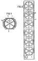
- FIG. 1 shows a housing 1 for an aluminum electrolytic capacitor shown, which is made of an aluminum casting with molded cooling fins 2.
- a mandrel 3 which is used to center the capacitor winding serves.
- ribs 4 arranged to a vibration-proof Serve to fix the capacitor winding.
- the heat flow out the capacitor winding takes place primarily via the protruding one Cathode and the cup bottom, the cooling fins 2 their full effect therefore only with low thermal resistance achieve along the cup wall.
- the housing 1 is flat, whereby several capacitor housings arranged side by side to save space can be as shown in Figure 2.
- the individual housings are inside an outer housing 7, which makes a particularly simple Assembly of the multiple housing 7 is guaranteed.
- the individual housing 1 are with their flat sides 5, 6 arranged against each other.
- FIG. 3 shows the parallel connection of capacitor windings 8, 9, 10, ... shown, which according to a housing Figure 2 are installed.
- the interconnection is done using a ribbon cable 11, which is designed as a simple "sandwich” is.
- the electrodes 12, 14 are with the anode 16 and cathode lugs 17 connected.
- FIG. 4 shows a further embodiment of a ribbon cable 11, which has a coaxial structure. Furthermore FIG. 4 contains the same reference symbols as FIG. 3.
- an insulating cup made of plastic (deep-drawn part) or the inner wall with an insulating material coat (e.g. rubber coating).
Landscapes
- Engineering & Computer Science (AREA)
- Power Engineering (AREA)
- Microelectronics & Electronic Packaging (AREA)
- Fixed Capacitors And Capacitor Manufacturing Machines (AREA)
- Secondary Cells (AREA)
- Electric Double-Layer Capacitors Or The Like (AREA)
- Glass Compositions (AREA)
- Oscillators With Electromechanical Resonators (AREA)
- Diaphragms For Electromechanical Transducers (AREA)
Description
- Figur 1
- ein Kondensatorgehäuse aus einem Aluminium-Gußteil,
- Figur 2
- eine Ausführungsform mit einem Mehrfachgehäuse und
- Figur 3 und 4
- Verschaltungen mit einer Bandleitung.
Claims (7)
- Aluminium-Elektrolytkondensator, insbesondere zur Anwendung in Kondensatorbatterien, der in ein mit Kühlrippen (2) versehenes Gehäuse (1) eingebaut ist,
dadurch gekennzeichnet, daß das Gehäuse (1) als Aluminium-Gußteil ausgebildet ist. - Aluminium-Elektrolytkondensator nach Anspruch 1,
dadurch gekennzeichnet, daß die Kühlrippen (2) an zwei gegenüberliegenden Gehäuseseiten (5, 6) flächig ausgebildet sind. - Aluminium-Elektrolytkondensator nach Anspruch 1 oder 2,
dadurch gekennzeichnet, daß das Gehäuse (7) zur Aufnahme mehrerer Kondensatoren (8, 9, 10, ...) ausgebildet ist. - Aluminium-Elektrolytkondensator nach Anspruch 3,
dadurch gekennzeichnet, daß das Gehäuse (1) auf seiner Innenseite eine isolierende Beschichtung aufweist. - Aluminium-Elektrolytkondensator nach Anspruch 3,
dadurch gekennzeichnet, daß im Gehäuse (1) isolierende Becher zur Aufnahme der Kondensatoren angeordnet sind. - Aluminium-Elektrolytkondensator nach einem der Ansprüche 1 bis 5,
dadurch gekennzeichnet, daß die Verschaltung mehrerer Kondensatoren (8, 9, 10, ...) in einer Kondensatorbatterie mittels sandwichartig ausgebildeter Bandleitungen (11) erfolgt. - Aluminium-Elektrolytkondensator nach Anspruch 6,
dadurch gekennzeichnet, daß die Bandleitungen (11) koaxial aufgebaut sind.
Applications Claiming Priority (3)
| Application Number | Priority Date | Filing Date | Title |
|---|---|---|---|
| DE19817493A DE19817493C1 (de) | 1998-04-20 | 1998-04-20 | Aluminium-Elektrolytkondensator |
| DE19817493 | 1998-04-20 | ||
| PCT/DE1999/001025 WO1999054893A1 (de) | 1998-04-20 | 1999-04-08 | Aluminium-elektrolytkondensator |
Publications (2)
| Publication Number | Publication Date |
|---|---|
| EP1080478A1 EP1080478A1 (de) | 2001-03-07 |
| EP1080478B1 true EP1080478B1 (de) | 2001-12-12 |
Family
ID=7865136
Family Applications (1)
| Application Number | Title | Priority Date | Filing Date |
|---|---|---|---|
| EP99924774A Expired - Lifetime EP1080478B1 (de) | 1998-04-20 | 1999-04-08 | Aluminium-elektrolytkondensator |
Country Status (8)
| Country | Link |
|---|---|
| EP (1) | EP1080478B1 (de) |
| JP (1) | JP2002512442A (de) |
| AT (1) | ATE210883T1 (de) |
| CA (1) | CA2329327A1 (de) |
| DE (2) | DE19817493C1 (de) |
| DK (1) | DK1080478T3 (de) |
| ES (1) | ES2169952T3 (de) |
| WO (1) | WO1999054893A1 (de) |
Families Citing this family (13)
| Publication number | Priority date | Publication date | Assignee | Title |
|---|---|---|---|---|
| DE10001120C2 (de) * | 2000-01-13 | 2003-07-24 | Epcos Ag | Induktionsarmer Elektrolyt-Kondensator |
| DE10117799A1 (de) * | 2001-04-10 | 2002-11-07 | Bosch Gmbh Robert | Kondensator |
| WO2005043970A1 (de) * | 2003-10-31 | 2005-05-12 | Siemens Aktiengesellschaft | Gehäusebecher für ein elektronisches bauteil mit integriertem kühlkörper |
| DE102004045182B4 (de) * | 2004-09-17 | 2008-10-16 | Epcos Ag | Kondensatormodul |
| DE102010043445B3 (de) | 2010-11-05 | 2012-04-19 | Semikron Elektronik Gmbh & Co. Kg | Kondensatoranordnung, leistungselektronisches Gerät damit undVerfahren zur Herstellung der Kondensatoranordnung |
| DE102011012631B4 (de) * | 2011-02-15 | 2020-11-12 | Sew-Eurodrive Gmbh & Co Kg | Energiespeicher |
| DE102011007315A1 (de) * | 2011-04-13 | 2012-10-18 | Robert Bosch Gmbh | Speichereinheit zum Speichern elektrischer Energie mit einem Kühlelement |
| DE102011081283A1 (de) * | 2011-08-19 | 2013-02-21 | Robert Bosch Gmbh | Kondensator mit einem Kühlkörper |
| EP2952377B1 (de) * | 2014-06-03 | 2017-10-04 | Visedo Oy | Kondensatormodul für eine mobile Arbeitsmaschine |
| KR101811988B1 (ko) | 2017-08-21 | 2017-12-22 | 대동콘덴서공업(주) | 방열판 일체형 고주파 대전류 커패시터 |
| DE102017223631A1 (de) | 2017-12-21 | 2019-06-27 | Robert Bosch Gmbh | Inverter für eine elektrische Maschine |
| DE102021123731A1 (de) | 2021-09-14 | 2023-03-16 | TDK Europe GmbH | Elektrisches Bauteil mit verbesserter Kühlung und entsprechendes Modul |
| DE102023003413A1 (de) * | 2023-08-18 | 2024-08-29 | Mercedes-Benz Group AG | Vorrichtung zum elektrischen Kontaktieren eines Kondensators |
Family Cites Families (4)
| Publication number | Priority date | Publication date | Assignee | Title |
|---|---|---|---|---|
| DE869509C (de) * | 1945-05-05 | 1953-03-05 | Asea Ab | Behaelter fuer elektrische Kondensatoren |
| US4447730A (en) * | 1980-07-11 | 1984-05-08 | Transnuklear Gmbh | Transportation and/or storage containers for radioactive materials |
| DE9203739U1 (de) * | 1992-03-19 | 1992-05-27 | Facon S.p.A. Fabbrica Condensatori Elettrici, Varese | Gehäuse für elektrische Kondensatoren |
| DE9213103U1 (de) * | 1992-09-29 | 1992-11-12 | Siemens Matsushita Components GmbH & Co. KG, 8000 München | Elektrolytkondensator für hohe Wechselstrombelastbarkeit |
-
1998
- 1998-04-20 DE DE19817493A patent/DE19817493C1/de not_active Expired - Fee Related
-
1999
- 1999-04-08 AT AT99924774T patent/ATE210883T1/de not_active IP Right Cessation
- 1999-04-08 ES ES99924774T patent/ES2169952T3/es not_active Expired - Lifetime
- 1999-04-08 JP JP2000545159A patent/JP2002512442A/ja not_active Withdrawn
- 1999-04-08 DK DK99924774T patent/DK1080478T3/da active
- 1999-04-08 DE DE59900550T patent/DE59900550D1/de not_active Expired - Fee Related
- 1999-04-08 WO PCT/DE1999/001025 patent/WO1999054893A1/de not_active Ceased
- 1999-04-08 EP EP99924774A patent/EP1080478B1/de not_active Expired - Lifetime
- 1999-04-08 CA CA002329327A patent/CA2329327A1/en not_active Abandoned
Also Published As
| Publication number | Publication date |
|---|---|
| ATE210883T1 (de) | 2001-12-15 |
| DK1080478T3 (da) | 2002-04-08 |
| DE19817493C1 (de) | 1999-08-26 |
| DE59900550D1 (de) | 2002-01-24 |
| WO1999054893A1 (de) | 1999-10-28 |
| CA2329327A1 (en) | 1999-10-28 |
| JP2002512442A (ja) | 2002-04-23 |
| ES2169952T3 (es) | 2002-07-16 |
| EP1080478A1 (de) | 2001-03-07 |
Similar Documents
| Publication | Publication Date | Title |
|---|---|---|
| EP1878031B1 (de) | Modul der leistungselektronik | |
| DE19817493C1 (de) | Aluminium-Elektrolytkondensator | |
| EP1496534B1 (de) | Hochleistungsschalter mit Kühlrippenanordnung | |
| WO2006111118A1 (de) | Leistungskondensator | |
| EP3906609B1 (de) | Elektrische maschine | |
| EP3504724B1 (de) | Elektroden gekühlte kondensator-baugruppe | |
| DE102009043181A1 (de) | Stromrichteranordnung | |
| DE3711192A1 (de) | Lager- und kuehleinrichtung fuer gleichrichterdioden bei elektrischen maschinen | |
| EP0514840A2 (de) | Kühlvorrichtung für mindestens einen Kondensator und Verfahren zu ihrer Herstellung | |
| EP1642334B1 (de) | Elektronisches leistungsmodul mit gummidichtung und entsprechendes herstellungsverfahren | |
| DE4338277C2 (de) | Flüssigkeitsgekühltes Stromrichtermodul mit Beschaltungsbauelementen für abschaltbare Leistungshalbleiter | |
| WO2018082824A1 (de) | Batterie mit einem wärmeabfuhrelement und verbindungsplatte | |
| DE102022207469A1 (de) | Kondensatoreinheit für einen Stromrichter und Verfahren zum Herstellen einer Kondensatoreinheit | |
| EP1678993B1 (de) | Gehäusebecher für ein elektronisches bauteil mit integriertem kühlkörper | |
| EP0180007A2 (de) | Elektrischer Wickelkondensator mit verringerter Eigeninduktivität | |
| WO2020103984A1 (de) | Batteriezelle | |
| DE102021118754B4 (de) | Kondensator, System mit mehreren Kondensatoren und Kraftfahrzeug | |
| WO2024193922A1 (de) | Kühlvorrichtung und gehäuse für eine schaltanordnung sowie schaltanordnung | |
| DE102022205764A1 (de) | Abstandselement für eine leiterplattenanordnung | |
| DE102011080950A1 (de) | Vorrichtung zur Wärmeabfuhr aus einem Energiespeicher | |
| DE10236525A1 (de) | Ventilbautelement-Satz in Zweigpaar-Konfiguration für einen elektrischen Wechselrichter | |
| DE102004043465B4 (de) | Gehäuse für mindestens ein elektronisches Bauteil bestehend aus zwei Gehäusebechern | |
| EP3457418A1 (de) | Niederinduktiver kondensator und kondensatorbank | |
| DE2705085A1 (de) | Wickelkondensator | |
| DE102021130457A1 (de) | Wickelkondensator, Pulswechselrichter und Kraftfahrzeug |
Legal Events
| Date | Code | Title | Description |
|---|---|---|---|
| PUAI | Public reference made under article 153(3) epc to a published international application that has entered the european phase |
Free format text: ORIGINAL CODE: 0009012 |
|
| 17P | Request for examination filed |
Effective date: 20001011 |
|
| AK | Designated contracting states |
Kind code of ref document: A1 Designated state(s): AT BE CH DE DK ES FI FR GB IT LI NL SE |
|
| GRAG | Despatch of communication of intention to grant |
Free format text: ORIGINAL CODE: EPIDOS AGRA |
|
| 17Q | First examination report despatched |
Effective date: 20010425 |
|
| GRAG | Despatch of communication of intention to grant |
Free format text: ORIGINAL CODE: EPIDOS AGRA |
|
| GRAH | Despatch of communication of intention to grant a patent |
Free format text: ORIGINAL CODE: EPIDOS IGRA |
|
| RAP1 | Party data changed (applicant data changed or rights of an application transferred) |
Owner name: EPCOS AG |
|
| GRAH | Despatch of communication of intention to grant a patent |
Free format text: ORIGINAL CODE: EPIDOS IGRA |
|
| GRAA | (expected) grant |
Free format text: ORIGINAL CODE: 0009210 |
|
| AK | Designated contracting states |
Kind code of ref document: B1 Designated state(s): AT BE CH DE DK ES FI FR GB IT LI NL SE |
|
| REF | Corresponds to: |
Ref document number: 210883 Country of ref document: AT Date of ref document: 20011215 Kind code of ref document: T |
|
| REG | Reference to a national code |
Ref country code: CH Ref legal event code: NV Representative=s name: E. BLUM & CO. PATENTANWAELTE Ref country code: CH Ref legal event code: EP |
|
| REG | Reference to a national code |
Ref country code: GB Ref legal event code: IF02 |
|
| GBT | Gb: translation of ep patent filed (gb section 77(6)(a)/1977) |
Effective date: 20011212 |
|
| REF | Corresponds to: |
Ref document number: 59900550 Country of ref document: DE Date of ref document: 20020124 |
|
| PGFP | Annual fee paid to national office [announced via postgrant information from national office to epo] |
Ref country code: FR Payment date: 20020319 Year of fee payment: 4 |
|
| PGFP | Annual fee paid to national office [announced via postgrant information from national office to epo] |
Ref country code: SE Payment date: 20020320 Year of fee payment: 4 Ref country code: AT Payment date: 20020320 Year of fee payment: 4 |
|
| PGFP | Annual fee paid to national office [announced via postgrant information from national office to epo] |
Ref country code: FI Payment date: 20020321 Year of fee payment: 4 Ref country code: DK Payment date: 20020321 Year of fee payment: 4 |
|
| REG | Reference to a national code |
Ref country code: DK Ref legal event code: T3 |
|
| PGFP | Annual fee paid to national office [announced via postgrant information from national office to epo] |
Ref country code: BE Payment date: 20020416 Year of fee payment: 4 |
|
| PGFP | Annual fee paid to national office [announced via postgrant information from national office to epo] |
Ref country code: ES Payment date: 20020509 Year of fee payment: 4 |
|
| ET | Fr: translation filed | ||
| REG | Reference to a national code |
Ref country code: ES Ref legal event code: FG2A Ref document number: 2169952 Country of ref document: ES Kind code of ref document: T3 |
|
| PLBE | No opposition filed within time limit |
Free format text: ORIGINAL CODE: 0009261 |
|
| STAA | Information on the status of an ep patent application or granted ep patent |
Free format text: STATUS: NO OPPOSITION FILED WITHIN TIME LIMIT |
|
| 26N | No opposition filed | ||
| PG25 | Lapsed in a contracting state [announced via postgrant information from national office to epo] |
Ref country code: GB Free format text: LAPSE BECAUSE OF NON-PAYMENT OF DUE FEES Effective date: 20030408 Ref country code: FI Free format text: LAPSE BECAUSE OF NON-PAYMENT OF DUE FEES Effective date: 20030408 Ref country code: AT Free format text: LAPSE BECAUSE OF NON-PAYMENT OF DUE FEES Effective date: 20030408 |
|
| PG25 | Lapsed in a contracting state [announced via postgrant information from national office to epo] |
Ref country code: SE Free format text: LAPSE BECAUSE OF NON-PAYMENT OF DUE FEES Effective date: 20030409 Ref country code: ES Free format text: LAPSE BECAUSE OF NON-PAYMENT OF DUE FEES Effective date: 20030409 |
|
| PG25 | Lapsed in a contracting state [announced via postgrant information from national office to epo] |
Ref country code: LI Free format text: LAPSE BECAUSE OF NON-PAYMENT OF DUE FEES Effective date: 20030430 Ref country code: DK Free format text: LAPSE BECAUSE OF NON-PAYMENT OF DUE FEES Effective date: 20030430 Ref country code: CH Free format text: LAPSE BECAUSE OF NON-PAYMENT OF DUE FEES Effective date: 20030430 Ref country code: BE Free format text: LAPSE BECAUSE OF NON-PAYMENT OF DUE FEES Effective date: 20030430 |
|
| BERE | Be: lapsed |
Owner name: *EPCOS A.G. Effective date: 20030430 |
|
| PG25 | Lapsed in a contracting state [announced via postgrant information from national office to epo] |
Ref country code: NL Free format text: LAPSE BECAUSE OF NON-PAYMENT OF DUE FEES Effective date: 20031101 |
|
| GBPC | Gb: european patent ceased through non-payment of renewal fee |
Effective date: 20030408 |
|
| NLV4 | Nl: lapsed or anulled due to non-payment of the annual fee |
Effective date: 20031101 |
|
| EUG | Se: european patent has lapsed | ||
| REG | Reference to a national code |
Ref country code: DK Ref legal event code: EBP |
|
| REG | Reference to a national code |
Ref country code: CH Ref legal event code: PL |
|
| PG25 | Lapsed in a contracting state [announced via postgrant information from national office to epo] |
Ref country code: FR Free format text: LAPSE BECAUSE OF NON-PAYMENT OF DUE FEES Effective date: 20031231 |
|
| REG | Reference to a national code |
Ref country code: FR Ref legal event code: ST |
|
| REG | Reference to a national code |
Ref country code: ES Ref legal event code: FD2A Effective date: 20030409 |
|
| PG25 | Lapsed in a contracting state [announced via postgrant information from national office to epo] |
Ref country code: IT Free format text: LAPSE BECAUSE OF NON-PAYMENT OF DUE FEES Effective date: 20050408 |
|
| PGFP | Annual fee paid to national office [announced via postgrant information from national office to epo] |
Ref country code: DE Payment date: 20080602 Year of fee payment: 10 |
|
| PG25 | Lapsed in a contracting state [announced via postgrant information from national office to epo] |
Ref country code: DE Free format text: LAPSE BECAUSE OF NON-PAYMENT OF DUE FEES Effective date: 20091103 |