EP1080305B1 - Brennstoffeinspritzventil - Google Patents
Brennstoffeinspritzventil Download PDFInfo
- Publication number
- EP1080305B1 EP1080305B1 EP99957921A EP99957921A EP1080305B1 EP 1080305 B1 EP1080305 B1 EP 1080305B1 EP 99957921 A EP99957921 A EP 99957921A EP 99957921 A EP99957921 A EP 99957921A EP 1080305 B1 EP1080305 B1 EP 1080305B1
- Authority
- EP
- European Patent Office
- Prior art keywords
- actuator
- fuel injection
- injection valve
- fuel
- valve according
- Prior art date
- Legal status (The legal status is an assumption and is not a legal conclusion. Google has not performed a legal analysis and makes no representation as to the accuracy of the status listed.)
- Expired - Lifetime
Links
Images

Classifications
-
- F—MECHANICAL ENGINEERING; LIGHTING; HEATING; WEAPONS; BLASTING
- F02—COMBUSTION ENGINES; HOT-GAS OR COMBUSTION-PRODUCT ENGINE PLANTS
- F02M—SUPPLYING COMBUSTION ENGINES IN GENERAL WITH COMBUSTIBLE MIXTURES OR CONSTITUENTS THEREOF
- F02M51/00—Fuel-injection apparatus characterised by being operated electrically
- F02M51/06—Injectors peculiar thereto with means directly operating the valve needle
-
- F—MECHANICAL ENGINEERING; LIGHTING; HEATING; WEAPONS; BLASTING
- F02—COMBUSTION ENGINES; HOT-GAS OR COMBUSTION-PRODUCT ENGINE PLANTS
- F02M—SUPPLYING COMBUSTION ENGINES IN GENERAL WITH COMBUSTIBLE MIXTURES OR CONSTITUENTS THEREOF
- F02M51/00—Fuel-injection apparatus characterised by being operated electrically
- F02M51/06—Injectors peculiar thereto with means directly operating the valve needle
- F02M51/0603—Injectors peculiar thereto with means directly operating the valve needle using piezoelectric or magnetostrictive operating means
-
- F—MECHANICAL ENGINEERING; LIGHTING; HEATING; WEAPONS; BLASTING
- F02—COMBUSTION ENGINES; HOT-GAS OR COMBUSTION-PRODUCT ENGINE PLANTS
- F02M—SUPPLYING COMBUSTION ENGINES IN GENERAL WITH COMBUSTIBLE MIXTURES OR CONSTITUENTS THEREOF
- F02M61/00—Fuel-injectors not provided for in groups F02M39/00 - F02M57/00 or F02M67/00
- F02M61/04—Fuel-injectors not provided for in groups F02M39/00 - F02M57/00 or F02M67/00 having valves, e.g. having a plurality of valves in series
- F02M61/08—Fuel-injectors not provided for in groups F02M39/00 - F02M57/00 or F02M67/00 having valves, e.g. having a plurality of valves in series the valves opening in direction of fuel flow
-
- F—MECHANICAL ENGINEERING; LIGHTING; HEATING; WEAPONS; BLASTING
- F02—COMBUSTION ENGINES; HOT-GAS OR COMBUSTION-PRODUCT ENGINE PLANTS
- F02M—SUPPLYING COMBUSTION ENGINES IN GENERAL WITH COMBUSTIBLE MIXTURES OR CONSTITUENTS THEREOF
- F02M63/00—Other fuel-injection apparatus having pertinent characteristics not provided for in groups F02M39/00 - F02M57/00 or F02M67/00; Details, component parts, or accessories of fuel-injection apparatus, not provided for in, or of interest apart from, the apparatus of groups F02M39/00 - F02M61/00 or F02M67/00; Combination of fuel pump with other devices, e.g. lubricating oil pump
- F02M63/0012—Valves
- F02M63/0057—Means for avoiding fuel contact with valve actuator, e.g. isolating actuators by using bellows or diaphragms
-
- F—MECHANICAL ENGINEERING; LIGHTING; HEATING; WEAPONS; BLASTING
- F02—COMBUSTION ENGINES; HOT-GAS OR COMBUSTION-PRODUCT ENGINE PLANTS
- F02M—SUPPLYING COMBUSTION ENGINES IN GENERAL WITH COMBUSTIBLE MIXTURES OR CONSTITUENTS THEREOF
- F02M2200/00—Details of fuel-injection apparatus, not otherwise provided for
- F02M2200/16—Sealing of fuel injection apparatus not otherwise provided for
Definitions
- the invention is based on a fuel injector according to the preamble of claim 1.
- valve needle Since the valve needle is firmly connected to the pressure shoulder, the valve needle on the spray side and the pressure shoulder sealing and moveable in the valve body are, the production is relatively complex and the fuel injector susceptible to bending or Tension of the valve needle or the change in relative positions of the two sliding surfaces.
- the fuel injector according to the invention with the Features of claim 1 has the advantage that a simple solution provides an inexpensive, low-wear, friction-free and considerably more compact Construction results. Furthermore, the seal is independent from the design of the valve needle and can therefore be Variety of fuel injectors can be integrated.
- the actuator jacket is advantageously wave-shaped or folded. This causes a large actuator stroke in the Actuator housing made possible in a compact design.
- the actuator is advantageously part of the actuator jacket a biasing force. Additional components, such as z. B. compression springs can be omitted.
- Advantageously is between the actuator jacket and the actuator thermally conductive material, in particular a thermal paste, intended. This means that when the actuator is actuated generated energy dissipated in the actuator from the actuator the thermally conductive material and from that to that Actuator housing are forwarded. This will make the thermal load on the actuator is reduced and the Fuel injector life extended.
- the seal advantageously has a tubular shape Sleeve that penetrates the recess of the actuator and the is at least partially enclosed by the actuator. As a result, the interior of the tubular sleeve is against the The actuator is sealed and the fuel can flow through it become.
- the seal advantageously has a on the sealing seat-side sealing plate with the actuator jacket and / or is connected to the sleeve. This enables the actuator on the sealing seat side sealing plate on devices of the Fuel injector act or on this support. In addition, the sealing plate on the sealing seat side similar to the inflow-side sealing plate, which simplifies the manufacture of the seal.
- the sealing plates are advantageously cup-shaped, whereby inside the sealing plates facilities of the fuel injector can be included. Moreover can make the sealing plates easier in a guide be performed.
- Each sealing plate advantageously has one Recess through which the sleeve passes.
- the sleeve is expanded on at least one sealing plate bent back and on one of the other sealing plate facing end face connected to this sealing plate. This enables a large actuator stroke in the actuator housing.
- At least one of the sealing plates is advantageously cup-shaped formed, and projects over an edge region of the sealing plate the bent-back area of the sleeve. This is the Protected bent-back area of the sleeve.
- the inlet-side sealing plate advantageously has at least one supply channel through which at least an electrical lead is led to the actuator. Thereby is the electrical lead in a simple manner in the Interior of the seal led.
- the feed channel against the fuel is advantageous sealed. This will seal the electrical Supply line against the fuel in the sealing plate integrated, eliminating the need for an additional seal can and results in a more compact design.
- the sleeve is part of a different one Fuel inlet nozzle extending to the sealing seat Fuel line. This simplifies the Fuel line especially for one end attached fuel connection. In addition, a additional fuel line is eliminated, which means Have components saved.
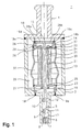
- Fig. 1 shows an axial excerpt Sectional view of a fuel injector according to the invention 1.
- the fuel injector 1 is used especially for direct fuel injection, especially of gasoline in a combustion chamber mixture-compressing, spark-ignited internal combustion engine as so-called gasoline direct injection valve.
- the Fuel injection valve 1 according to the invention is suitable however also for other applications.
- the fuel injector 1 is an internal one Fuel injector 1 executed.
- the fuel injector 1 has a valve housing 3 and a Fuel inlet connector 4 representing fuel inlet on, which together the housing of the fuel injector 1 form.
- the valve closing body 6 is frustoconical tapering in the spray direction educated.
- the valve closing body 6 acts with one a valve seat surface 8 formed to a valve seat body 7 a sealing seat together.
- the valve needle 5 is at her axial movement through valve needle guides 9, 10, which are attached to the valve housing 3. To the flow of The valve needle guides show how to enable fuel 9, 10 slot-shaped recesses 11, 12.
- A is used to actuate the fuel injection valve 1 Actuator 13, the piezoelectric or magnetostrictive is executed.
- the actuator 13 is actuated via an electrical control signal via an electrical Lead, which in this embodiment is simplicity is not shown for the sake of being guided to the actuator 13 becomes.
- the actuator 13 When the actuator 13 is actuated, it expands and acts on an inflow-side sealing plate 14 on a Base plate 15, on which the valve needle 5 is attached, wherein the actuator 13 is on a sealing seat side Supporting sealing plate 16 on the valve housing 3. This will the valve needle 5 in the axial direction on the fuel inlet connector 4 moves, causing the Valve closing body 6 from the valve seat 8 Valve seat body 7 lifts and releases the sealing seat.
- valve closing body 6 and Valve seat body 7 causes fuel to escape a fuel chamber 17 of the fuel injection valve 1 into the combustion chamber of the internal combustion engine.
- valve needle 5 takes place in the embodiment via a Compression spring 18, which is on one side on the Base plate 15 and on the other side to the fuel inlet connector 4 supports.
- valve housing 3 The valve housing 3, the fuel inlet port 4, the Base plate 15, the inflow-side sealing plate 14 and sealing plate side sealing plate 16 are welded 19a - 19f attached to each other. The attachment can also done on another tit.
- the actuator jacket 20 is over a circumferential weld 22 with the inflow side Sealing plate 14 and with a circumferential weld 23 with the sealing seat side sealing plate 16 is non-detachably connected.
- the connection can also be different, in particular releasable be executed.
- the inflow-side sealing plate 14 and the sealing plate-side sealing plate 16 have inner recesses 24, 25 through which the sleeve 21 passes, wherein the sleeve 21 on the inflow-side sealing plate 14 in one bent back area 39 is bent back and on a circumferential weld seam 26 with an end face 37 the inflow-side sealing plate 14 and on a circumferential Weld seam 27 with the sealing plate 16 on the sealing seat side connected is.
- the inflow-side sealing plate 14 has one Edge area 38 on which the inflow-side sealing plate 14 is connected to the base plate 15. A bent back Area 39 of sleeve 21 is separated from edge area 38 the inflow-side sealing plate 14 protrudes.
- the inflow-side sealing plate 14 Through the Pot-shaped formation of the inflow-side sealing plate 14 can the expanded on the inflow-side sealing plate 14 and bent back sleeve 21 when the actuator 13 in Direction of the fuel inlet port 4 are moved, wherein the sealing of the actuator 13 by the sealing 14, 16, 20, 21 against the fuel remains. From the for the same reason, the actuator jacket 20 is wave-shaped or folded. In this case, through the actuator jacket 20 a bias voltage is transmitted to the actuator 13 so that the compression spring 18 can be omitted.
- the fuel is supplied via the Fuel inlet port 4, through holes 28a, 28b in the Base plate 15 and through an inner longitudinal opening 31 Sleeve 21, through which valve needle 5 also extends, into the fuel chamber 17.
- the fuel line can alternatively also via the interior 29 of the valve housing 3 take place, then suitable flow openings in the sealing plate-side sealing plate 16 are to be provided.
- a space 30 between the actuator jacket 20 and the Actuator 13 can be a thermally conductive material, in particular a thermal paste can be introduced, whereby the heat of the Actuator 13 via the thermal paste in the intermediate space 30 and via the sealing seat side sealing plate 16 to the Valve housing 3 is passed.
- a thermal paste can be introduced, whereby the heat of the Actuator 13 via the thermal paste in the intermediate space 30 and via the sealing seat side sealing plate 16 to the Valve housing 3 is passed.
- the space between the actuator 13 and the sleeve 21 with a thermal paste to apply heat to the Dispense fuel In a corresponding way also the space between the actuator 13 and the sleeve 21 with a thermal paste to apply heat to the Dispense fuel.
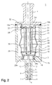
- Fig. 2 shows an axial excerpt Sectional view of a second embodiment of the Fuel injector according to the invention 1. Already described elements are with matching Provide reference numerals so that a repetitive Description unnecessary.
- the fuel injector 1 is an externally opening fuel injector 1.
- the pot-shaped, inflow-side Sealing plate 14 is supported on the fuel inlet connection 4, so that when the actuator 13 is actuated Direction of the sealing seat and over the sealing seat side sealing plate 16 and the base plate 15 the valve needle 5 acts, whereby the truncated cone-shaped trained to expand in the spray direction Valve closing body 6, in one piece with the valve needle 5 is formed from the valve seat surface 8 of the Valve seat body 7 lifts and releases the sealing seat.
- the compression spring 18 which is located on the one hand on the valve housing 3 and on the other hand is supported on the base plate 15, the Valve closing body 6 against the valve seat surface 8 of the Valve seat body 7 pressed.
- the Function of the compression spring 18 completely or partially Actuator jacket 20 are taken over.
- the electrical lead to the actuator 13 can Supply channels 32 and 33 in the fuel inlet port 4 and take place in the sealing plate 14.
- the feed channels 32, 33 can also vent the seal 14, 16, 20, 21 or for the drainage of leakage liquid from the seal 14, 16, 20, 21 serve.
- the inflow of fuel towards the Sealing seat takes place via the longitudinal opening 31 and bores 28a, 28b in the base plate 15.
- a thermally conductive Material in particular a thermal paste, introduced his.
- Fig. 3 shows another in a sectional view Embodiment of the seal 14, 16, 20 of the actuator 13.
- Der Actuator jacket 20 is over circumferential weld seams 22 and 23 to the inflow-side sealing plate 14 or the sealing plate-side sealing plate 16 welded.
- the actuator 13 is located between the two cup-shaped Sealing plates 14, 16.
- a supply channel 33 for receiving an electrical line to the actuator 13 is in the inflow-side sealing plate 14 is provided.
- the Supply channel 33 can, however, also in the sealing seat side Sealing plate 16 may be provided.
- Fig. 4 shows another in a sectional view Embodiment of the inflow-side sealing plate 14.
- the feed channel 33 executed kinked, the supply channel 33 on the Circumferential surface 35 of the inflow-side sealing plate 14 opens.
- the inflow-side sealing plate 14 With the peripheral surface 35, the inflow-side sealing plate 14 on the inner wall of the valve housing 3, in particular by Welding. This allows the electrical Line via a connection in the valve housing 3 is to be provided from the side of the fuel injector 1 through the feed channel 33 to the actuator 13.
- the opening of the feed channel 33 on the peripheral surface 35 is to prevent the ingress of fuel to seal the fuel. This is particularly suitable a weld seam running around the opening between the Circumferential surface 35 and the valve housing 3.
- the attachment of the actuator jacket 20 can be a smaller one Diameter than the upper peripheral surface 35 having lower peripheral surface 36 of the inflow-side sealing plate 14 respectively.
- the one described is suitable without restriction Execution of the inflow-side sealing plate 14 also for the sealing plate side sealing plate 16.
- the sealing plate 14 has the possibility of supplying fuel a fuel channel 40.
- the invention is not based on those described Embodiments limited.
- One is in particular different design of the actuator jacket 20, the sleeve 21, in particular the bent-back region 39 of the sleeve 21, and the two sealing plates 14, 16 conceivable.
- Furthermore is the action of the actuator 13 on the valve needle 5 in the 1 and 2 are shown in simplified form and are intended to illustrate the invention do not restrict in this regard. Especially draws the invention through the possibility of using the Seal 14, 16, 20, 21 in a variety of fuel injectors 1 off.
Landscapes
- Engineering & Computer Science (AREA)
- Chemical & Material Sciences (AREA)
- Combustion & Propulsion (AREA)
- Mechanical Engineering (AREA)
- General Engineering & Computer Science (AREA)
- Fuel-Injection Apparatus (AREA)
- Electrically Driven Valve-Operating Means (AREA)
Description
- Fig. 1
- einen auszugsweisen axialen Schnitt durch ein erstes Ausführungsbeispiel eines erfindungsgemäßen Brennstoffeinspritzventils, wobei das Brennstoffeinspritzventil nach innen öffnend ausgeführt ist;
- Fig. 2
- einen auszugsweisen axialen Schnitt durch ein zweites Ausführungsbeispiel eines erfindungsgemäßen Brennstoffeinspritzventils, wobei das Brennstoffeinspritzventil nach außen öffnend ausgeführt ist;
- Fig. 3
- einen axialen Schnitt durch einen Aktor mit Abdichtung; und
- Fig. 4
- einen axialen Schnitt durch eine Dichtplatte.
Claims (17)
- Brennstoffeinspritzventil (1), insbesondere Einspritzventil für Brennstoffeinspritzanlagen von Brennkraftmaschinen, mit einem Brennstoffeinlaß (4) zum Zuführen von Brennstoff, einem piezoelektrischen oder magnetostriktiven Aktor (13), der durch eine Abdichtung (14, 16, 20, 21) gegen den Brennstoff abgedichtet ist, und einem von dem Aktor (13) mittels einer Ventilnadel (5) betätigbaren Ventilschließkörper (6), der mit einer Ventilsitzfläche (8) zu einem Dichtsitz zusammenwirkt,
dadurch gekennzeichnet, daß die Abdichtung (14, 16, 20, 21) eine zuflußseitige Dichtplatte (14), die zwischen dem Brennstoffeinlaß (4) und dem Aktor (13) angeordnet ist, und einen in Längsrichtung elastisch verformbaren Aktormantel (20) umfaßt, der mit der zuflußseitigen Dichtplatte (14) verbunden ist. - Brennstoffeinspritzventil nach Anspruch 1,
dadurch gekennzeichnet, daß die zuflußseitige Dichtplatte (14) topfförmig ausgebildet ist. - Brennstoffeinspritzventil nach einem der Ansprüche 1 oder 2,
dadurch gekennzeichnet, daß der Aktormantel (20) wellenförmig oder gefaltet ausgebildet ist. - Brennstoffeinspritzventil nach einem der Ansprüche 1 bis 3,
dadurch gekennzeichnet, daß der Aktor (13) von dem Aktormantel (20) mit einer Vorspannkraft beaufschlagt ist. - Brennstoffeinspritzventil nach einem der Ansprüche 1 bis 4,
dadurch gekennzeichnet, daß zwischen dem Aktormantel (20) und dem Aktor (13) ein wärmeleitfähiges Material, insbesondere eine Wärmeleitpaste, vorgesehen ist. - Brennstoffeinspritzventil nach einem der Ansprüche 1 bis 5,
dadurch gekennzeichnet, daß der Aktor (13) eine innere Längsöffnung (31) aufweist. - Brennstoffeinspritzventil nach Anspruch 6,
dadurch gekennzeichnet, daß die Abdichtung (14, 16, 20, 21) eine rohrförmige Hülse (21) aufweist, die die Längsöffnung (31) des Aktors (13) durchdringt und die von dem Aktor (13) zumindest abschnittsweise umschlossen ist. - Brennstoffeinspritzventil nach einem der Ansprüche 1 bis 7,
dadurch gekennzeichnet, daß die Abdichtung (14, 16, 20, 21) eine dichtsitzseitige Dichtplatte (16) umfaßt, die mit dem Aktormantel (20) und/oder mit der Hülse (21) verbunden ist. - Brennstoffeinspritzventil nach Anspruch 8,
dadurch gekennzeichnet, daß die dichtsitzseitige Dichtplatte (16) topfförmig ausgebildet ist. - Brennstoffeinspritzventil nach Anspruch 8 oder 9,
dadurch gekennzeichnet, daß die Dichtplatten (14, 16) jeweils eine Aussparung (24, 25) aufweisen, durch welche die Hülse (21) hindurchtritt, und
daß die Hülse (21) an zumindest einer Dichtplatte (14) aufgeweitet zurückgebogen ist und an einer der jeweils anderen Dichtplatte (16) abgewandten Stirnfläche (37) mit der Dichtplatte (14) verbunden ist. - Brennstoffeinspritzventil nach einem der Ansprüche 8 bis 10,
dadurch gekennzeichnet, daß zumindest eine der Dichtplatten (14, 16) topfförmig ausgebildet ist und ein Randbereich (38) der Dichtplatte (14) den zurückgebogenen Bereich (39) der Hülse (21) überragt. - Brennstoffeinspritzventil nach einem der Ansprüche 1 bis 11,
dadurch gekennzeichnet, daß die zuflußseitige Dichtplatte (14) zumindest einen Zuleitungskanal (33) aufweist, durch welchen zumindest eine elektrische Zuleitung an den Aktor (13) geführt ist. - Brennstoffeinspritzventil nach Anspruch 12,
dadurch gekennzeichnet, daß der Zuleitungskanal (33) gegen den Brennstoff abgedichtet ist. - Brennstoffeinspritzventil nach einem der Ansprüche 1 bis 13,
dadurch gekennzeichnet, daß der Aktor (13) über die zuflußseitige Dichtplatte (14) auf die Ventilnadel (5) einwirkt. - Brennstoffeinspritzventil nach einem der Ansprüche 7 bis 14,
dadurch gekennzeichnet, daß die Ventilnadel (5) abschnittsweise von der Hülse (21) umschlossen ist. - Brennstoffeinspritzventil nach einem der Ansprüche 8 bis 11,
dadurch gekennzeichnet, daß der Aktor (13) über die dichtsitzseitige Dichtplatte (16) auf die Ventilnadel (5) einwirkt. - Brennstoffeinspritzventil nach einem der Ansprüche 7 bis 16,
dadurch gekennzeichnet, daß die Hülse (21) Teil einer sich von dem Brennstoffeinlaß (4) bis zum Dichtsitz erstreckenden Brennstoffleitung ist.
Applications Claiming Priority (3)
| Application Number | Priority Date | Filing Date | Title |
|---|---|---|---|
| DE19912666 | 1999-03-20 | ||
| DE19912666A DE19912666A1 (de) | 1999-03-20 | 1999-03-20 | Brennstoffeinspritzentil |
| PCT/DE1999/003357 WO2000057049A1 (de) | 1999-03-20 | 1999-10-20 | Brennstoffeinspritzventil |
Publications (3)
| Publication Number | Publication Date |
|---|---|
| EP1080305A1 EP1080305A1 (de) | 2001-03-07 |
| EP1080305B1 true EP1080305B1 (de) | 2002-07-31 |
| EP1080305B2 EP1080305B2 (de) | 2012-04-25 |
Family
ID=7901815
Family Applications (1)
| Application Number | Title | Priority Date | Filing Date |
|---|---|---|---|
| EP99957921A Expired - Lifetime EP1080305B2 (de) | 1999-03-20 | 1999-10-20 | Brennstoffeinspritzventil |
Country Status (6)
| Country | Link |
|---|---|
| US (2) | US6435430B1 (de) |
| EP (1) | EP1080305B2 (de) |
| JP (1) | JP4469506B2 (de) |
| KR (1) | KR100658955B1 (de) |
| DE (2) | DE19912666A1 (de) |
| WO (1) | WO2000057049A1 (de) |
Cited By (1)
| Publication number | Priority date | Publication date | Assignee | Title |
|---|---|---|---|---|
| EP1788232A1 (de) | 2005-11-16 | 2007-05-23 | Siemens Aktiengesellschaft | Aktorvorrichtung und Fluidinjektor |
Families Citing this family (30)
| Publication number | Priority date | Publication date | Assignee | Title |
|---|---|---|---|---|
| DE19912666A1 (de) * | 1999-03-20 | 2000-09-21 | Bosch Gmbh Robert | Brennstoffeinspritzentil |
| DE19946869A1 (de) * | 1999-09-30 | 2001-04-05 | Bosch Gmbh Robert | Brennstoffeinspritzventil |
| JP4356268B2 (ja) | 2000-06-26 | 2009-11-04 | 株式会社デンソー | 燃料噴射装置 |
| ITBO20010279A1 (it) * | 2001-05-08 | 2002-11-08 | Magneti Marelli Spa | Iniettore di carburante con attuatore piezoelettrico alloggiato in una camera isolata |
| DE10136807A1 (de) * | 2001-07-27 | 2003-02-13 | Bosch Gmbh Robert | Brennstoffeinspritzventil |
| DE10139550A1 (de) * | 2001-08-10 | 2003-03-06 | Bosch Gmbh Robert | Hülse für ein Piezo-Aktormodul |
| DE10140799A1 (de) * | 2001-08-20 | 2003-03-06 | Bosch Gmbh Robert | Brennstoffeinspritzventil |
| US6811093B2 (en) * | 2002-10-17 | 2004-11-02 | Tecumseh Products Company | Piezoelectric actuated fuel injectors |
| DE10259801A1 (de) * | 2002-12-19 | 2004-07-01 | Robert Bosch Gmbh | Brennstoffeinspritzventil |
| DE10360451B4 (de) * | 2003-02-27 | 2014-01-09 | Robert Bosch Gmbh | Brennstoffeinspritzventil |
| US7500648B2 (en) | 2003-02-27 | 2009-03-10 | Robert Bosch Gmbh | Fuel-injection valve |
| US9380269B2 (en) * | 2003-09-23 | 2016-06-28 | Time Warner Cable Enterprises Llc | Scheduling trigger apparatus and method |
| DE10344880A1 (de) * | 2003-09-26 | 2005-04-14 | Robert Bosch Gmbh | Brennstoffeinspritzventil |
| DE10353641B4 (de) * | 2003-11-17 | 2016-12-01 | Robert Bosch Gmbh | Brennstoffeinspritzventil |
| DE102005001005B4 (de) * | 2005-01-07 | 2008-11-20 | Continental Automotive Gmbh | Stellantrieb zur Betätigung eines Kraftstoffeinspritzventils |
| DE102006006076B4 (de) * | 2006-02-09 | 2014-10-02 | Continental Automotive Gmbh | Piezo-Aktor, Verfahren zum Herstellen eines Piezo-Aktors und Einspritzsystem mit einem solchen |
| DE102006012845A1 (de) * | 2006-03-21 | 2007-10-04 | Daimlerchrysler Ag | Injektor für Speichereinspritzsysteme |
| DE102006014251A1 (de) * | 2006-03-28 | 2007-10-04 | Robert Bosch Gmbh | Kraftstoffinjektor |
| US7717132B2 (en) * | 2006-07-17 | 2010-05-18 | Ford Global Technologies, Llc | Hydraulic valve actuated by piezoelectric effect |
| DE102006043027A1 (de) * | 2006-09-13 | 2008-03-27 | Epcos Ag | Verspannelement und Piezoaktor mit dem Verspannelement |
| DE102006059694A1 (de) * | 2006-12-18 | 2008-06-19 | Robert Bosch Gmbh | Aktormodul mit einem umhüllten Piezoaktor und Verfahren zu dessen Herstellung |
| DE102007008901B4 (de) * | 2007-02-23 | 2008-10-16 | Compact Dynamics Gmbh | Fluid-Einspritzventil |
| DE102008008111A1 (de) * | 2008-02-08 | 2009-08-13 | Continental Automotive Gmbh | Einspritzventil, Verfahren und Vorrichtung zur Steuerung eines Einspritzventils |
| US7665445B2 (en) * | 2008-04-18 | 2010-02-23 | Caterpillar Inc. | Motion coupler for a piezoelectric actuator |
| EP2149699B1 (de) * | 2008-07-29 | 2014-09-24 | Continental Automotive GmbH | Kraftstoffeinspritzdüse |
| DE102008041544B4 (de) * | 2008-08-26 | 2016-05-12 | Robert Bosch Gmbh | Ventil zur Zumessung eines flüssigen oder gasförmigen Mediums |
| JP5585178B2 (ja) * | 2010-04-13 | 2014-09-10 | いすゞ自動車株式会社 | 流体制御装置 |
| DE102010042476A1 (de) * | 2010-10-14 | 2012-04-19 | Robert Bosch Gmbh | Vorrichtung zum Einspritzen von Kraftstoff |
| WO2015055553A1 (en) | 2013-10-14 | 2015-04-23 | Continental Automotive Gmbh | Injection valve |
| JP7600601B2 (ja) * | 2020-03-23 | 2024-12-17 | 株式会社リコー | 吐出ヘッド、吐出ユニット、液体を吐出する装置 |
Family Cites Families (18)
| Publication number | Priority date | Publication date | Assignee | Title |
|---|---|---|---|---|
| JPS57136859U (de) * | 1981-02-18 | 1982-08-26 | ||
| JPS60104762A (ja) | 1983-11-10 | 1985-06-10 | Nippon Soken Inc | 電歪式アクチュエータ及びそれを用いた燃料噴射弁 |
| US4803393A (en) * | 1986-07-31 | 1989-02-07 | Toyota Jidosha Kabushiki Kaisha | Piezoelectric actuator |
| JPS63207185A (ja) * | 1987-02-23 | 1988-08-26 | Toyota Motor Corp | 圧電アクチユエ−タ |
| JPS63223361A (ja) † | 1987-03-13 | 1988-09-16 | Hitachi Metals Ltd | 圧電駆動式燃料噴射器 |
| JPH02112663A (ja) † | 1989-09-20 | 1990-04-25 | Hitachi Ltd | 内燃機関用の燃料噴射弁 |
| US5035637A (en) * | 1990-05-04 | 1991-07-30 | Navistar International Transportation Corp. | Engine valve cover gasket with electrical bridge |
| JPH04179286A (ja) † | 1990-11-14 | 1992-06-25 | Nec Corp | 積層圧電アクチュエータ |
| DE19534445C2 (de) | 1995-09-16 | 1998-07-30 | Man Nutzfahrzeuge Ag | Einspritzventil für Brennkraftmaschinen |
| DE19650900A1 (de) † | 1996-12-07 | 1998-06-10 | Bosch Gmbh Robert | Piezoelektrischer Aktuator |
| DE19653555C2 (de) * | 1996-12-20 | 2002-10-31 | Siemens Ag | Piezoelektrischer Aktor |
| US5979803A (en) * | 1997-05-09 | 1999-11-09 | Cummins Engine Company | Fuel injector with pressure balanced needle valve |
| GB9725804D0 (en) * | 1997-12-06 | 1998-02-04 | Lucas Ind Plc | Fuel injector |
| DE19843570A1 (de) † | 1998-09-23 | 2000-03-30 | Bosch Gmbh Robert | Brennstoffeinspritzventil |
| DE19843940A1 (de) | 1998-09-24 | 2000-03-30 | Mannesmann Rexroth Ag | Kraftstoffeinspritzsystem |
| GB9823028D0 (en) * | 1998-10-22 | 1998-12-16 | Lucas Ind Plc | Fuel injector |
| DE19849203A1 (de) † | 1998-10-26 | 2000-04-27 | Bosch Gmbh Robert | Brennstoffeinspritzventil |
| DE19912666A1 (de) * | 1999-03-20 | 2000-09-21 | Bosch Gmbh Robert | Brennstoffeinspritzentil |
-
1999
- 1999-03-20 DE DE19912666A patent/DE19912666A1/de not_active Withdrawn
- 1999-10-20 KR KR1020007013013A patent/KR100658955B1/ko not_active Expired - Fee Related
- 1999-10-20 JP JP2000606891A patent/JP4469506B2/ja not_active Expired - Fee Related
- 1999-10-20 WO PCT/DE1999/003357 patent/WO2000057049A1/de not_active Ceased
- 1999-10-20 US US09/701,097 patent/US6435430B1/en not_active Expired - Lifetime
- 1999-10-20 EP EP99957921A patent/EP1080305B2/de not_active Expired - Lifetime
- 1999-10-20 DE DE59902197T patent/DE59902197D1/de not_active Expired - Lifetime
-
2002
- 2002-07-12 US US10/194,693 patent/US6889913B2/en not_active Expired - Fee Related
Cited By (1)
| Publication number | Priority date | Publication date | Assignee | Title |
|---|---|---|---|---|
| EP1788232A1 (de) | 2005-11-16 | 2007-05-23 | Siemens Aktiengesellschaft | Aktorvorrichtung und Fluidinjektor |
Also Published As
| Publication number | Publication date |
|---|---|
| US20030015601A1 (en) | 2003-01-23 |
| US6435430B1 (en) | 2002-08-20 |
| DE59902197D1 (de) | 2002-09-05 |
| JP4469506B2 (ja) | 2010-05-26 |
| DE19912666A1 (de) | 2000-09-21 |
| KR20010025057A (ko) | 2001-03-26 |
| EP1080305A1 (de) | 2001-03-07 |
| US6889913B2 (en) | 2005-05-10 |
| JP2002540341A (ja) | 2002-11-26 |
| WO2000057049A1 (de) | 2000-09-28 |
| EP1080305B2 (de) | 2012-04-25 |
| KR100658955B1 (ko) | 2006-12-19 |
Similar Documents
| Publication | Publication Date | Title |
|---|---|---|
| EP1080305B1 (de) | Brennstoffeinspritzventil | |
| EP1115970B1 (de) | Brennstoffeinspritzventil | |
| EP1149237B2 (de) | Brennstoffeinspritzventil | |
| EP1080304B1 (de) | Brennstoffeinspritzventil | |
| WO1998040623A1 (de) | Ventil zum steuern von flüssigkeiten | |
| EP1119703B1 (de) | Brennstoffeinspritzventil | |
| EP3559437B1 (de) | Ventil zum zumessen eines fluids | |
| DE10039424A1 (de) | Dosierventil mit einem hydraulischen Übertragungselement | |
| EP1421271B1 (de) | Brennstoffeinspritzventil | |
| DE10333696A1 (de) | Kraftstoffeinspritzvorrichtung | |
| DE10149052A1 (de) | Verbesserte Struktur einer Kraftstoffeinspritzeinrichtung zum Vermeiden des Einspritzens einer übermässigen Kraftstoffmenge | |
| EP2786010B1 (de) | Ventil zum zumessen eines strömenden mediums | |
| EP1651855B1 (de) | Kraftstoffeinspritzvorrichtung | |
| EP1519036B1 (de) | Brennstoffeinspritzventil | |
| WO2003054382A1 (de) | Brennstoffeinspritzventil | |
| EP2458194B1 (de) | Kraftstoffeinspritzventil für Brennkraftmaschinen | |
| EP1488096B1 (de) | Brennstoffeinspritzventil | |
| DE10353641B4 (de) | Brennstoffeinspritzventil | |
| DE102009002897A1 (de) | Kraftstoffinjektor | |
| EP1519034B1 (de) | Brennstoffeinspritzventil | |
| DE19911047A1 (de) | Brennstoffeinspritzventil | |
| EP1544454B1 (de) | Brennstoffeinspritzventil | |
| DE10032924A1 (de) | Kraftstoffeinspritzvorrichtung für Brennkraftmaschinen | |
| DE10332090B4 (de) | Brennstoffeinspritzventil | |
| DE19928205A1 (de) | Brennstoffeinspritzventil |
Legal Events
| Date | Code | Title | Description |
|---|---|---|---|
| PUAI | Public reference made under article 153(3) epc to a published international application that has entered the european phase |
Free format text: ORIGINAL CODE: 0009012 |
|
| AK | Designated contracting states |
Kind code of ref document: A1 Designated state(s): AT BE CH CY DE DK ES FI FR GB GR IE IT LI LU MC NL PT SE |
|
| 17P | Request for examination filed |
Effective date: 20010328 |
|
| GRAG | Despatch of communication of intention to grant |
Free format text: ORIGINAL CODE: EPIDOS AGRA |
|
| 17Q | First examination report despatched |
Effective date: 20010925 |
|
| GRAG | Despatch of communication of intention to grant |
Free format text: ORIGINAL CODE: EPIDOS AGRA |
|
| GRAH | Despatch of communication of intention to grant a patent |
Free format text: ORIGINAL CODE: EPIDOS IGRA |
|
| GRAH | Despatch of communication of intention to grant a patent |
Free format text: ORIGINAL CODE: EPIDOS IGRA |
|
| GRAA | (expected) grant |
Free format text: ORIGINAL CODE: 0009210 |
|
| AK | Designated contracting states |
Kind code of ref document: B1 Designated state(s): DE FR GB IT |
|
| REG | Reference to a national code |
Ref country code: GB Ref legal event code: FG4D Free format text: NOT ENGLISH |
|
| REG | Reference to a national code |
Ref country code: IE Ref legal event code: FG4D Free format text: GERMAN |
|
| REF | Corresponds to: |
Ref document number: 59902197 Country of ref document: DE Date of ref document: 20020905 |
|
| GBT | Gb: translation of ep patent filed (gb section 77(6)(a)/1977) |
Effective date: 20021007 |
|
| ET | Fr: translation filed | ||
| REG | Reference to a national code |
Ref country code: IE Ref legal event code: FD4D Ref document number: 1080305E Country of ref document: IE |
|
| PLBI | Opposition filed |
Free format text: ORIGINAL CODE: 0009260 |
|
| PLBQ | Unpublished change to opponent data |
Free format text: ORIGINAL CODE: EPIDOS OPPO |
|
| PLBF | Reply of patent proprietor to notice(s) of opposition |
Free format text: ORIGINAL CODE: EPIDOS OBSO |
|
| 26 | Opposition filed |
Opponent name: SIEMENS AG Effective date: 20030430 |
|
| PLAX | Notice of opposition and request to file observation + time limit sent |
Free format text: ORIGINAL CODE: EPIDOSNOBS2 |
|
| PLAX | Notice of opposition and request to file observation + time limit sent |
Free format text: ORIGINAL CODE: EPIDOSNOBS2 |
|
| PLBB | Reply of patent proprietor to notice(s) of opposition received |
Free format text: ORIGINAL CODE: EPIDOSNOBS3 |
|
| PLAB | Opposition data, opponent's data or that of the opponent's representative modified |
Free format text: ORIGINAL CODE: 0009299OPPO |
|
| APBM | Appeal reference recorded |
Free format text: ORIGINAL CODE: EPIDOSNREFNO |
|
| APBP | Date of receipt of notice of appeal recorded |
Free format text: ORIGINAL CODE: EPIDOSNNOA2O |
|
| APAH | Appeal reference modified |
Free format text: ORIGINAL CODE: EPIDOSCREFNO |
|
| APBQ | Date of receipt of statement of grounds of appeal recorded |
Free format text: ORIGINAL CODE: EPIDOSNNOA3O |
|
| APBU | Appeal procedure closed |
Free format text: ORIGINAL CODE: EPIDOSNNOA9O |
|
| PUAH | Patent maintained in amended form |
Free format text: ORIGINAL CODE: 0009272 |
|
| STAA | Information on the status of an ep patent application or granted ep patent |
Free format text: STATUS: PATENT MAINTAINED AS AMENDED |
|
| 27A | Patent maintained in amended form |
Effective date: 20120425 |
|
| AK | Designated contracting states |
Kind code of ref document: B2 Designated state(s): DE FR GB IT |
|
| REG | Reference to a national code |
Ref country code: DE Ref legal event code: R102 Ref document number: 59902197 Country of ref document: DE Effective date: 20120425 |
|
| REG | Reference to a national code |
Ref country code: FR Ref legal event code: PLFP Year of fee payment: 17 |
|
| REG | Reference to a national code |
Ref country code: FR Ref legal event code: PLFP Year of fee payment: 18 |
|
| REG | Reference to a national code |
Ref country code: FR Ref legal event code: PLFP Year of fee payment: 19 |
|
| PGFP | Annual fee paid to national office [announced via postgrant information from national office to epo] |
Ref country code: FR Payment date: 20171023 Year of fee payment: 19 Ref country code: DE Payment date: 20171206 Year of fee payment: 19 |
|
| PGFP | Annual fee paid to national office [announced via postgrant information from national office to epo] |
Ref country code: IT Payment date: 20171020 Year of fee payment: 19 Ref country code: GB Payment date: 20171024 Year of fee payment: 19 |
|
| REG | Reference to a national code |
Ref country code: DE Ref legal event code: R119 Ref document number: 59902197 Country of ref document: DE |
|
| GBPC | Gb: european patent ceased through non-payment of renewal fee |
Effective date: 20181020 |
|
| PG25 | Lapsed in a contracting state [announced via postgrant information from national office to epo] |
Ref country code: DE Free format text: LAPSE BECAUSE OF NON-PAYMENT OF DUE FEES Effective date: 20190501 |
|
| PG25 | Lapsed in a contracting state [announced via postgrant information from national office to epo] |
Ref country code: FR Free format text: LAPSE BECAUSE OF NON-PAYMENT OF DUE FEES Effective date: 20181031 |
|
| PG25 | Lapsed in a contracting state [announced via postgrant information from national office to epo] |
Ref country code: GB Free format text: LAPSE BECAUSE OF NON-PAYMENT OF DUE FEES Effective date: 20181020 Ref country code: IT Free format text: LAPSE BECAUSE OF NON-PAYMENT OF DUE FEES Effective date: 20181020 |