EP1079246A1 - Lichtleiterbündel mit mantellosen Lichtwellenleitern - Google Patents
Lichtleiterbündel mit mantellosen Lichtwellenleitern Download PDFInfo
- Publication number
- EP1079246A1 EP1079246A1 EP99202494A EP99202494A EP1079246A1 EP 1079246 A1 EP1079246 A1 EP 1079246A1 EP 99202494 A EP99202494 A EP 99202494A EP 99202494 A EP99202494 A EP 99202494A EP 1079246 A1 EP1079246 A1 EP 1079246A1
- Authority
- EP
- European Patent Office
- Prior art keywords
- light
- light guide
- window
- channel
- angle
- Prior art date
- Legal status (The legal status is an assumption and is not a legal conclusion. Google has not performed a legal analysis and makes no representation as to the accuracy of the status listed.)
- Withdrawn
Links
Images


Classifications
-
- G—PHYSICS
- G02—OPTICS
- G02B—OPTICAL ELEMENTS, SYSTEMS OR APPARATUS
- G02B6/00—Light guides; Structural details of arrangements comprising light guides and other optical elements, e.g. couplings
- G02B6/02—Optical fibres with cladding with or without a coating
- G02B6/032—Optical fibres with cladding with or without a coating with non solid core or cladding
-
- G—PHYSICS
- G02—OPTICS
- G02B—OPTICAL ELEMENTS, SYSTEMS OR APPARATUS
- G02B6/00—Light guides; Structural details of arrangements comprising light guides and other optical elements, e.g. couplings
- G02B6/04—Light guides; Structural details of arrangements comprising light guides and other optical elements, e.g. couplings formed by bundles of fibres
- G02B6/06—Light guides; Structural details of arrangements comprising light guides and other optical elements, e.g. couplings formed by bundles of fibres the relative position of the fibres being the same at both ends, e.g. for transporting images
Definitions
- the present invention relates to a light guide member. More particularly the invention relates to a light guide member for use in a read out apparatus wherein a stimulable phosphor sheet on which a radiation image has been stored is illuminated with stimulating rays which cause the phosphor to emit light in proportion to the amount of energy stored therein during its exposure to radiation, and wherein light emitted upon stimulation is guided by the light guide member from the phosphor to a light detector.
- a first type of such light guide members consists of a sheet of light transmitting material. In a read out apparatus one end of the sheet is placed adjacent to a scan line and the other end is located adjacent to the light receiving face of a photodetector.
- the end of the light guiding member which is adjacent to the scan line is shaped into a linear form and the other end which is to be located adjacent to the light receiving face of a photodetector is shaped into an annular form to be adapted to the light receiving face of the photodetector.
- a light guide member of the above-named kind has been described in United states patent US 4, 485, 302.
- the described light guide member is made of a material that is transparent to light emitted by the phosphor. It is finished to have a smooth surface so that the light transmitted thereto is effectively subjected to total reflection by the internal surface.
- Suitable materials which have adequate properties for light guiding are transparent thermoplastic resins such as acrylic resin, vinyl chloride resin, polycarbonate resin, polyester resin, epoxy resin or glass.
- Portions of the light guide member which are adjacent to the output end faces are cut into a plurality of strips which are bundled, and end faces of the bundled strips are located in close contact with a detector, e.g. a photodetector.
- the shape of the sheet should be optimised and its surface should be smoothed.
- the light guide member should be made of a transparent sheet curled into a shape having a linear or arcuate inlet and an annular outlet.
- the curvature of the sheet should be made small so as not to interrupt the repeated internal reflections.
- the length of the sheet should be long enough to allow the small curvature.
- Another type of light guide members consists of a number of individual optical fibres that are arranged in a row at the side of the phosphor sheet to be scanned and bundled at the side of the photodetector.
- optical fibers used in this type of light guide are conventional optical fibers that consist of a core material surrounded by a solid cladding material having a lower refractive index than that of the core material.
- Light emitted by a phosphor upon stimulation enters the light guide member and is guided inside the fibres by internal reflection towards the output end of the light guide member where the fibers are bundled e.g. to form a circular plane that can be coupled to the entrance window of a detector such as a photomultiplier.
- the numerical aperture of the optical fibers decreases since even at moderate curvature the optical fibers are no longer able to guide marginal rays of light entering the input window of the light guide towards the output window.
- the light guide members consisting of optical fibers may loose about 15 to 20 % of their optical efficiency.
- the new concept supports a light acceptance angle of 180 degrees equivalent to a numerical aperture equal to 1.
- the concept of the present invention is thus advantageous in that a much higher numerical aperture can be attained. This higher numerical aperture remains constant over a wider curvature range of the light guiding member.
- the light-guide assembly can have a single or multiple input and output windows.
- the spectrum of the light can cover areas such as :
- Ultra-Violet, Visual and Infra-Red thereby supporting efficient transport of photons from narrow and wide band spectrum light-sources.
- the transfer of light between input and output is done by a multitude of light-channels.
- These channels have a solid structure and can be made out of any type of light-guiding material with a low degree of internal scattering and with a low absorption for the spectrum of the light it has to transport from input to output.
- Possible channel materials are optical grade plastics such as polymethylmethacrylaat (in the following referred to as PMMA), Poly Carbonate and Poly Styrene or they can be any member of a silica-based variety of optical glass materials.
- the light carrier itself does not have a solid cladding material with a lower refractive index surrounding the core material. Instead the light channel according to the present invention entirely consists of "core" material.
- core channels are suspended in a gas having a much lower refractive index than the core material. This concept ensures the highest possible numerical aperture even at relatively strong curvatures when compared with conventional fiber technology, as will be proved further on.
- Ambient air or other gasses can be used as cladding gas.
- the light-guide assembly can consist of channels with different cross-sections and cross-section shapes.
- Circles, ellipses, squares, rectangles, hexagons or any other type of polygon or free shape can be used as the light-channels cross-section shape.
- the individual light channels preferably have a constant or increasing cross-section along the channel's three dimensional trajectory from input to output.
- the individual light-channels are fused at the light input and/or light output sides by heat and by pressure to form core material blocks.
- These blocks preferably have the shape of the input and/or output windows of the light guide.
- the fusion-depth of the material block is preferably a few millimeters along the light-trajectory. Within the fused areas the boundaries of the individual channels have completely disappeared.
- the blocks do not contain gaseous or other enclosures they are totally transparent and have a full 100% fill-factor at the window surfaces. This is especially important for the light-collection efficiency at the input-window.
- the 100% hermetically sealed solid window-blocks may be polished for efficient light-coupling.
- optical fiber assemblies may loose 15 to 20% of optical efficiency due to the inter-fiber surface losses and the cladding material surface losses at the input window.
- the window blocks are suspended at the input and/or output windows by means of optical window plates.
- the same material as the core material is used for the window plates, alternatively they can be glass-based or plastic-based too.
- these plates can be glued to the core material blocks.
- index-matching optical cement is used for glueing in order to obtain minimal added reflections at the interfaces.
- window plates should preferably be spectrally suited to guide the light travelling through the light-guide.
- a surrounding system is provided and arranged to hold the window plates in place.
- An alternative but optically slightly less performing way of holding the fused and polished window blocks is to grab them at the sides by means of a tight-fitting frame-work of short reflectors.
- the reflectors are arranged along the trajectory path's extremities.
- These reflectors should preferably be specular and spectrally suited to reflect the light travelling in the lightguide.
- a surrounding system can be provided to hold the reflectors in place.
- the light-guide assembly is suspended in a surrounding gas (the "clad" material ). It may be protected from contamination and from entrance of external light by means of a light-tight and dust-tight enclosure spanning the input and output windows. This cover is preferably not touching the individual light channels.
- the light-guide can be equipped with an optional antireflection coating or it can be coupled with other system components using optical oil mounts (removable) or optical cement (fixed).
- An optional anti-reflex coating, the oil mount or the cement helps to reduce optical reflections at the light-guides boundaries and should preferably be spectrally suited to guide the light.
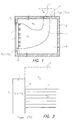
- Figure 1 shows a first embodiment of a light guide according to the present invention. This first embodiment is referred to as the window-plate type embodiment.
- the light guide comprises a bundle of individual non-cladded light channels 1 suspended in a light and dust tight enclosure 2 preferably made out of a low evaporation type material such as aluminum or ABS "Novodur" (Acrylnitril-Butadien-Styrolcopolymer, Novodur is a trade name of Bayer AG).
- a low evaporation type material such as aluminum or ABS “Novodur” (Acrylnitril-Butadien-Styrolcopolymer, Novodur is a trade name of Bayer AG).
- the bundle extends from an entrance window 3 to an output window 4 .
- the individual light channels consist of core material.
- the refractive index of this material is ⁇ 2 .
- this core material is polymethylmethacrylaat.
- the bundle of light channels is surrounded by a cladding gas 5 , having a refractive index ⁇ 3 , which should be much lower than the refractive index of the core material.
- this cladding gas is air.
- the individual light channels are fused (by heat and pressure) to become a core material block 6 .
- This block has the shape of the light-guide's window and the fusion-depth is a few millimeters in the direction of the trajectory the light follows within the light guide. Within the fused areas the boundaries of the individual channels have completely disappeared.
- the window block(s) 6 are suspended at the input window and occasionally at the output window by means of optical window plates 7 .
- window plates should preferably be spectrally suited to guide the light travelling through the light-guide.
- the window plates are for example plastic-based or glass-based materials, having a refractive index ⁇ 12 (for input window) or ⁇ 34 (for output window).
- the plate material is the same material as used for the light guiding channels because this provides best optical efficiency. (In this case ⁇ 12 and/or ⁇ 34 equal(s) ⁇ 2 .
- the window plates are made of polymethylmethacrylaat.
- the window plates 7 can be fused or glued to the core material blocks at the outer ends of the light guides.
- the core material blocks have been fused and polished.
- the glueing to the light guide's core material blocks is preferably done with index-matching optical cement for optimal light-coupling.
- This example features a rectangular input window of 7mm x 330mm with a maximum trajectory length of 500mm between the input and output windows.
- the input window surface equals 2310mm2.
- 3 layers are stacked to a 60 degree stacked height of 8.196 mm ( optimally stacked ) in close proximity of the input window.
- Two layers contain 110 channels and one layer contains 109 channels. These 329 channels represent a total PMMA surface equal to 2326 mm2.
- a Cross-Section Compression Factor (CSCF ) of 1.007 results from compressing these three heated layers to a rectangular solid PMMA block with dimensions: 7mm x 330mm (equal to the input-window surface).
- the output bundle diameter is 58mm when the 329 channels are arranged into a circular bundle.
- Optimal optical efficiency is obtained by taking care that the corner 10 between the window plate 7 and the bundle of light channels 1 is very clean and that the outer side surface 11 of the light channel bundle is clean, glossy and scratch fee, that the cladding gas 5 is a pure and inert gas so that no chemical reaction occurs with the channel material and with the enclosure material which could have an etching effect on the channels or could deposit a substance with a different refractive index to the channel walls.
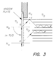
- Figure 3 illustrates the trajectory followed by rays of light entering the light guide.
- the numerical aperture of the light guide of this example is equal to 1, the maximum angle i is ⁇ /2.
- the fill factor being defined as the ratio between the total surface of all the light-guide material within a window relative to the windows total surface is equal to 100%. It is an extremely important factor at the input window and should be equal to 1 for best optical coupling between a light-source and the light-guide.
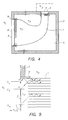
- Figure 4 shows a light channel arrangement of a second kind. This embodiment is referred to as the side reflector type light guide.
- the light guide shown in figure 4 comprises a bundle of non-cladded individual light channels 1 suspended in a light and dust tight enclosure 2 made of a low evaporation type material such as aluminum or ABS "Novodur".
- the bundle extends from an entrance window 3 to an output window 4 .
- the bundle of light channels is surrounded by a cladding gas 5 , having a refractive index ⁇ 3 , in this example this gas is air.
- the individual light channels are likewise fused (by heat and pressure) to become core material blocks 6 having the shape of the light-guides windows 3 and/or 4 .
- the fusion-depth is a few millimeters along the light-trajectory.
- the core material block(s) 6 are not suspended at the input window and occasionally at the output window by means of optical window plates but by means of side reflectors 7 .
- figure 5 shows the trajectory followed by rays of light entering the light guide at the entrance window.
- the channel walls are preferably parallel or diverging resulting in constant or increasing cross-section from input to output, for reasons that will be explained below. This is illustrated in figure 6.
- the entrance angle increases so that the angle at which rays hit the inner wall of the channel will never become smaller than the critical angle. Consequentially these rays will always reach the end of the channel while in case of a converging channel (see higher) it is possible that some rays will not reach the end of the channel (depending on the length of the channel and the degree of convergence).
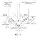
- Figure 7 illustrates a comparison between the efficiency of light guiding by a light guide according to conventional fiber technology and a light guide based on non-cladded channel technology according to the present invention.
- light is emitted by a source of radiation having a diffuse Lambertian behaviour.
- This kind of behaviour corresponds with the behaviour of the light that is guided in a specific application in which the present invention is used, namely in the case wherein light is emitted by a photostimulable phosphor screen upon stimulation and guided by a light guide according to the present invention towards a detector.
- the photostimulable phosphor screen emitting light likewise has a diffuse Lambertian behaviour.
- the maximum acceptance angle is defined as the angle below which all rays of light are accepted by the fiber.
- this maximum acceptance angle i max is smaller than ⁇ , more specifically the maximum input angle is approximately equal to 31° corresponding with a maximum acceptance angle of 62°.
- the maximum numerical aperture N.A. which is defined as ⁇ 1 . sin i max is thus smaller than 1 in case of conventional fiber technology (approximately 0.51) and equal to 1 in case of non-cladded fibers according to the present invention.
- Light rays entering a light guide of the conventional type (prior art type) under an angle which is larger than the maximal entrance angle i max will not be able to reach the output window of the light guide so the optical efficiency of conventional light guides is limited while for the light channels of the present invention such constraints do not exist.
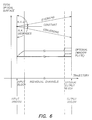
- the graph of figure 8 shows the relation between optical transmission efficiency (ability of transmitting light) and the numerical aperture for light emitted by a light source having a Lambertian behaviour.
- the optical transmission efficiency is expressed by the 'Lambertian transmission' T L which value is proportional to (N.A.) 2 .
- the graph shows that the optical efficiency increases almost quadratically with increasing numerical aperture.
- a small divergence from the quadratic behaviour at numerical aperture values that are greater than 0.5 is due to the fastly increasing Fresnel reflection losses at the input window of a light guide with increasing entrance angle.
- Non-cladded fibers are thus more efficient light guides than optical fibers based on conventional fiber technology because the former appear to have a much high numerical aperture resulting in a much higher light transmission.
- the 100% active input window provides an optimized interface of light source and light guide entrance.
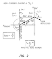
- Figures 9 and 10 illustrate the difference which exists between the numerical aperture values attained for non-cladded channels and for conventional fiber technology. This explanation is based on the total internal reflection criterion. Light which falls onto the input window of a light guide will, after having been refracted, reach the output window by repeated internal, lossless reflections at the inner walls of the light channels (fibers).
- Figure 9 and 10 also illustrate the margin available for total internal reflection of an incoming ray in both cases (prior art and according to the present invention).
- Total internal reflection margins are compared for conventional light guiding optical fiber technology relative to non-cladded light guides.
- Figure 9 relates to the case of non-cladded light channels.
- the interface at the side wall of the light channel is an interface between the material out of which the light guide made (the core material) and the cladding gas.
- the cladding gas is air, it has a refractive index which is approximately equal to 1 so that the critical angle is relatively small.
- the critical angle is indicated as an angle ⁇ in figure 9. Total internal reflection is obtained when a ray hits the side wall of the light guide under an angle relative to the normal to the side wall which is larger than the critical angle ⁇ .
- figure 9 a ray of light is shown which is incident at maximal entrance angle i max equal to ⁇ /2. The ray thus enters the light guide in a direction which is parallel to the entrance window of the light guide.
- a portion of this ray is refracted at the entrance window and then enters the light guide under an angle with the normal on the entrance window being denoted ⁇ .
- the refracted ray is guided within the light guide onto the side-wall of the light guide where it is internally reflected because the critical angle ⁇ (being the angle below which all rays are accepted by the fiber for internal reflection) is smaller than the angle which is made by the ray relative to the normal on the side-wall of the light guide.
- the difference between the angle made by the ray relative to the normal on the side-wall in the point where the ray impinges the side wall and the angle ⁇ is referred to as the total internal reflection margin angle ⁇ .
- this margin angle ⁇ is positive. All rays that, after being refracted at the entrance window, reach the side-wall of the light guide under an angle that is larger than ⁇ will be totally internally reflected. No losses will occur.
- the criterium for total internal reflection is that the angle ⁇ needs to be positive.
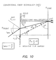
- the cladding gas is here replaced by a cladding solid material having a refractive index denoted by ⁇ 3* , which is also in this case smaller than the refractive index ⁇ 2 of the core material.
- ⁇ 3* refractive index
- ⁇ 2 refractive index
- this difference is much smaller than in the previous case (see figure 9) so that the critical angle ⁇ * has become larger than ⁇ .
- a ray which enters the optical fiber under an angle of ⁇ /2 with the entrance window will, after having been refracted, reach the side wall of the core of the light guide, in this case being the interface between core and cladding material at an angle which is smaller than ⁇ *, and will thus leave the light guide at the core wall instead of being internally reflected.
- the ray will be absorbed and diffused inside the solid cladding layer.
- This angle will certainly be smaller than ⁇ /2. Thus this angle is certainly smaller than the result obtained in case of the light channels according to the present invention.
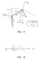
- Figure 11 illustrates how the total reflection margin ⁇ will decrease with increasing curvature of the trajectory.
- Figure 11 illustrates what happens with curved trajectories.
- the margin ⁇ decreases with increasing trajectory curvature because the normal to the side wall rotates with increasing curvature towards the incoming ray.
- Figure 12 illustrates the worst case orientation for curved trajectories.
- Incoming light travels by means of a multitude of individual optical light channels according to the present invention from an input window to an output window of the light guide.
- the cross section's shape can be a circle, an ellipse, a triangle, a square, a rectangular, a polygon or even any shape as depicted.
- the individual channel trajectories may thus all be different.
- channel trajectories are non-linear with multiple curvatures due to the different spatial locations of entrance and output window(s) of the light guide.
- Channel torsion combined with natural or even engineered channel randomisation can lead to nearly unpredictable channel trajectories and to huge variations of the orientation of the channel's cross section shape relative to the center of the channel-curvature.
- the channels curvatures are the weakest points in this respect since the light traveling through the channels may escape due to a local lack of total internal reflection at overcurved trajectories where the radius of curvature is too small.
- the minimal curvature radius which still provides total internal reflection into the channel depends on several parameters such as numerical aperture of the light guide, refractive index of the channel material and of the surrounding cladding gas(ses), channel thickness as a function of channel cross section, shape and worst case orientation of the shape relative to the local center of channel-curvature.
- Light can escape from a light guide when the angle between the steepest rays hitting the channel's surface from the inside and the line through that point of incidence and perpendicular to the channel's surface is smaller than the critical angle needed to preserve the total internal reflection character of the channel's boundaries.
- This critical situation will first occur for the steepest ray internally reflected at the inner side starting point of a curvature with a critical radius given the channel's cross sectional shape is at its worst case orientation relative to the curvature center resulting in a highest channel thickness.
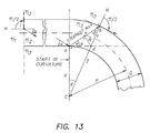
- the worst case shape orientation relative to a line AB containing the center of local curvature c can be found in general if the following conditions are met: For all point a, b of the channel's contour (1) line AB is perpendicular to the surface tangent in point a, (2) the distance between the points a and b is a maximum, (3) all points p on the line AB between points a and b are points of the channel's cross section.
- Figure 13 graphically represents a light channel with a numerical aperture N.A. equal to 1.
- This ray is refracted at the entrance window and enters the light guide under an angle denoted by ⁇ and impinges the inner surface of the light channel at location ⁇ a' located at the start of the curvature.
- This ray represents the steepest ray since for all other rays entering the entrance window the angle of entrance in the light channel after refraction at the entrance window will be smaller than ⁇ .
- the margin angle of 6 degrees corresponds to an entrance angle of ⁇ /2 and thus constitutes the positive margin angle which is available in the case of light guides according to this invention comprising non-cladded light channels.
- T.I.R. margin As the light channel is curved the total internal reflection margin (T.I.R. margin) also decreases.
- the graph representing the T.I.R. margin ⁇ has been drawn for which at an entrance angle of ⁇ /2 the zero T.I.R. margin is obtained. This graph is referred to as 'marginally curved'. This situation occurs if the R/D curvature value equals 9.822.
- a third graph is an example of an overcurved situation, i.e. a situation where a zero T.I.R. margin is already attained for input angles smaller than ⁇ /2. This graph is referred to as 'overcurved'. In the drawn example a zero TIR margin is attained for an input angle of 50 degrees.
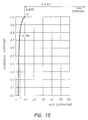
- the numerical aperture is indicated as a function of the R/D curvature value.
- the numerical aperture is equal to the maximum value 1 for straight channels and remains equal to '1' for curved channels until the ratio R/D is equal to about 10. Further, for still smaller values of R/D the numerical aperture decreases but is still equal to 0.766 for an R/D value equal to 4.
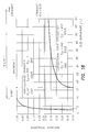
- Fig. 16 applies to an example of a conventional prior art light guide consisting of a core material surrounded by a solid cladding material.
- Figure 16 relates to a commercially available light guide which has a numerical aperture equal to 0.51 (acceptance angle equal to 62°).
- the light guide consists of a core material and a cladding solid material which has a refractive index equal to 1.402.
- the critical angle ⁇ has increased to a large extent due to the higher index of refraction of the cladding material when compared with the cladding gas used in the light guiding means in accordance with the present invention.
- the T.I.R. margin (for straight trajectory) has decreased and attains a negative value of minus 22 degrees at an input angle i equal to ⁇ /2.
- the maximal input angle has decreased to 25°- (numerical aperture 0.42) and at even larger curvature, e.g. at an R/D value equal to 18, the maximal input angle has decreased to 10° (numerical aperture 0.17).
- a minimal ratio R/D equal to 16.078 is required to obtain propagation of all rays entering at zero degrees (maximal input angle equal to zero) via the prior art light guiding means towards the output window. This represents a N.A. equal to zero. Only collimated light sources are able to send light through the thus curved fiber.
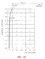
- the graph shown in figure 17 shows the behaviour of the numerical aperture as a function of the curvature of the trajectory for conventional optical fibers. This figure is to be compared with figure 15, which shows the numerical aperture as a function of the curvature of the trajectory for non-cladded fibers according to the invention.
- the numerical aperture decreases when the trajectory is curved due to the absense of any T.I.R. margin for conventional light guides.
- Figure 18 shows the most important differences between the characteristics of non-cladded light channels according to the present invention and prior art light guides based on conventional optical fibers having a core and a solid cladding material surrounding the core.
- the maximal numerical aperture is different for conventional fiber technology and for non-cladded light channels.
- Non-cladded channels according to the present invention have a numerical aperture equal to 1.
- the maximal numerical aperture for conventional fiber technology is less than 1.
- the value of the numerical aperture remains equal to 1 for even strong curvature of the trajectory of the light channel.
- this value decreases from the slightest curvature of the channel on.
- a light guide based on conventional fiber technology that is curved to such an extent that it has a R/D value smaller than 16.078 is no longer able to transmit a single ray of light from an entrance window to an output window. Furthermore, the numerical aperture of such a light guide attains a value equal to zero while for non-cladded channels the numerical aperture at this curvature is still maximal and equal to 1.
- the numerical aperture remains constant within a wide range of degrees of curvature strength. The value only starts to decrease for curved trajectories having an R/D value which is smaller than 9.822.
- the non-cladded channels attain the maximal numerical aperture of conventional fiber technology when they are curved to a large extent, namely when R/D is equal to 3.
- non-cladded light channels according to the present invention are more efficient and can be made more compact than light guides based on conventional state of the art fiber technology since (1) they have the highest, approximately constant numerical aperture value when transmitting light emitted by a lambertian light source at the input window and (2) they can be curved to a large extent at an identical or even higher numerical aperture than conventional fibers.
- the light guide can be made more compact by using a much smaller curvature radius for the same fiber diameter resulting in the same or higher efficiency compared to a light guide based on conventional fiber technology.
Landscapes
- Physics & Mathematics (AREA)
- General Physics & Mathematics (AREA)
- Optics & Photonics (AREA)
- Optical Fibers, Optical Fiber Cores, And Optical Fiber Bundles (AREA)
- Radiography Using Non-Light Waves (AREA)
- Light Guides In General And Applications Therefor (AREA)
Priority Applications (4)
| Application Number | Priority Date | Filing Date | Title |
|---|---|---|---|
| EP99202494A EP1079246A1 (de) | 1999-07-28 | 1999-07-28 | Lichtleiterbündel mit mantellosen Lichtwellenleitern |
| US09/619,109 US6496633B1 (en) | 1999-07-28 | 2000-07-19 | Light guide |
| JP2000229083A JP2001066441A (ja) | 1999-07-28 | 2000-07-28 | 光ガイド |
| US10/197,028 US20030049004A1 (en) | 1999-07-28 | 2002-07-17 | Light guide |
Applications Claiming Priority (1)
| Application Number | Priority Date | Filing Date | Title |
|---|---|---|---|
| EP99202494A EP1079246A1 (de) | 1999-07-28 | 1999-07-28 | Lichtleiterbündel mit mantellosen Lichtwellenleitern |
Publications (1)
| Publication Number | Publication Date |
|---|---|
| EP1079246A1 true EP1079246A1 (de) | 2001-02-28 |
Family
ID=8240507
Family Applications (1)
| Application Number | Title | Priority Date | Filing Date |
|---|---|---|---|
| EP99202494A Withdrawn EP1079246A1 (de) | 1999-07-28 | 1999-07-28 | Lichtleiterbündel mit mantellosen Lichtwellenleitern |
Country Status (2)
| Country | Link |
|---|---|
| EP (1) | EP1079246A1 (de) |
| JP (1) | JP2001066441A (de) |
Citations (4)
| Publication number | Priority date | Publication date | Assignee | Title |
|---|---|---|---|---|
| US3950073A (en) * | 1973-05-23 | 1976-04-13 | Nippon Telegraph & Telephone Public Corporation | Eccentric core optical waveguide |
| US5013128A (en) * | 1990-06-07 | 1991-05-07 | General Dynamics Corporation, Convair Division | Fiber optic light guide with improved end-to-end efficiency |
| DE4332699A1 (de) * | 1993-09-25 | 1995-03-30 | Thomson Brandt Gmbh | Verfahren zur Erhöhung des effektiven Öffnungsverhältnisses von Flüssigkristall-Lichtventilen |
| US5693043A (en) * | 1985-03-22 | 1997-12-02 | Massachusetts Institute Of Technology | Catheter for laser angiosurgery |
Family Cites Families (3)
| Publication number | Priority date | Publication date | Assignee | Title |
|---|---|---|---|---|
| JPS5424646A (en) * | 1977-07-26 | 1979-02-24 | Matsushita Electronics Corp | Fiber optical device |
| JP3383412B2 (ja) * | 1993-08-03 | 2003-03-04 | 富士通ディスプレイテクノロジーズ株式会社 | 導光体群、列状導光体、、光源装置及び液晶表示装置 |
| JPH09258053A (ja) * | 1996-03-25 | 1997-10-03 | Matsushita Electric Works Ltd | 光ファイバ |
-
1999
- 1999-07-28 EP EP99202494A patent/EP1079246A1/de not_active Withdrawn
-
2000
- 2000-07-28 JP JP2000229083A patent/JP2001066441A/ja active Pending
Patent Citations (4)
| Publication number | Priority date | Publication date | Assignee | Title |
|---|---|---|---|---|
| US3950073A (en) * | 1973-05-23 | 1976-04-13 | Nippon Telegraph & Telephone Public Corporation | Eccentric core optical waveguide |
| US5693043A (en) * | 1985-03-22 | 1997-12-02 | Massachusetts Institute Of Technology | Catheter for laser angiosurgery |
| US5013128A (en) * | 1990-06-07 | 1991-05-07 | General Dynamics Corporation, Convair Division | Fiber optic light guide with improved end-to-end efficiency |
| DE4332699A1 (de) * | 1993-09-25 | 1995-03-30 | Thomson Brandt Gmbh | Verfahren zur Erhöhung des effektiven Öffnungsverhältnisses von Flüssigkristall-Lichtventilen |
Also Published As
| Publication number | Publication date |
|---|---|
| JP2001066441A (ja) | 2001-03-16 |
Similar Documents
| Publication | Publication Date | Title |
|---|---|---|
| JP4170677B2 (ja) | 光源装置及びディスプレイ | |
| US5055978A (en) | Uniform light source | |
| US5857761A (en) | Illumination device | |
| US4733929A (en) | Diffuser fiber incident energy concentrator and method of using same | |
| KR101691248B1 (ko) | 터치 및 사물 감지 디스플레이를 위한 조명 장치 | |
| US4720426A (en) | Reflective coating for solid-state scintillator bar | |
| US20100098377A1 (en) | Light confinement using diffusers | |
| KR940004777B1 (ko) | 자극성 인광체 패널 판독장치 | |
| JP2628858B2 (ja) | 光誘導管 | |
| US4799748A (en) | Slab-diffuser fiber incident energy concentrator | |
| CA2204607A1 (en) | Prismatic refracting optical array for liquid flat panel crystal display backlight | |
| JP2010026505A (ja) | 集光光ファイバ | |
| US6496633B1 (en) | Light guide | |
| WO2014110770A1 (zh) | 光导入系统、侧入式背光模组及液晶显示器 | |
| US6180955B1 (en) | Integrating optical collector with reduced re-illumination of phosphor sheet | |
| JPH0797167B2 (ja) | 光バンドルフアイバの端末構造 | |
| EP1079246A1 (de) | Lichtleiterbündel mit mantellosen Lichtwellenleitern | |
| JP2931298B2 (ja) | 側面発光光ファイバ | |
| US4973128A (en) | High gain optical fiber viewing device | |
| US20050135741A1 (en) | System and method for extending viewing angle of light emitted from light pipe | |
| JP4171055B2 (ja) | ディスプレイ装置 | |
| JP2722436B2 (ja) | 照明光学装置 | |
| KR20090119561A (ko) | 광파이프 및 이를 구비한 조명 장치 | |
| US11237332B1 (en) | Direct optical coupling of scanning light engines to a waveguide | |
| EP1221631A1 (de) | Hoch effiziente Lichtleitervorrichtung |
Legal Events
| Date | Code | Title | Description |
|---|---|---|---|
| PUAI | Public reference made under article 153(3) epc to a published international application that has entered the european phase |
Free format text: ORIGINAL CODE: 0009012 |
|
| AK | Designated contracting states |
Kind code of ref document: A1 Designated state(s): DE FR GB |
|
| AX | Request for extension of the european patent |
Free format text: AL;LT;LV;MK;RO;SI |
|
| 17P | Request for examination filed |
Effective date: 20010828 |
|
| AKX | Designation fees paid |
Free format text: DE FR GB |
|
| RAP1 | Party data changed (applicant data changed or rights of an application transferred) |
Owner name: AGFA-GEVAERT |
|
| STAA | Information on the status of an ep patent application or granted ep patent |
Free format text: STATUS: THE APPLICATION IS DEEMED TO BE WITHDRAWN |
|
| 18D | Application deemed to be withdrawn |
Effective date: 20061202 |