EP1078649B1 - An apparatus for treating a living organism to achieve a heart load reduction - Google Patents
An apparatus for treating a living organism to achieve a heart load reduction Download PDFInfo
- Publication number
- EP1078649B1 EP1078649B1 EP00117449A EP00117449A EP1078649B1 EP 1078649 B1 EP1078649 B1 EP 1078649B1 EP 00117449 A EP00117449 A EP 00117449A EP 00117449 A EP00117449 A EP 00117449A EP 1078649 B1 EP1078649 B1 EP 1078649B1
- Authority
- EP
- European Patent Office
- Prior art keywords
- heart
- pulse
- accordance
- patient
- wave
- Prior art date
- Legal status (The legal status is an assumption and is not a legal conclusion. Google has not performed a legal analysis and makes no representation as to the accuracy of the status listed.)
- Expired - Lifetime
Links
Images


Classifications
-
- A—HUMAN NECESSITIES
- A61—MEDICAL OR VETERINARY SCIENCE; HYGIENE
- A61N—ELECTROTHERAPY; MAGNETOTHERAPY; RADIATION THERAPY; ULTRASOUND THERAPY
- A61N1/00—Electrotherapy; Circuits therefor
- A61N1/18—Applying electric currents by contact electrodes
- A61N1/32—Applying electric currents by contact electrodes alternating or intermittent currents
- A61N1/36—Applying electric currents by contact electrodes alternating or intermittent currents for stimulation
- A61N1/36014—External stimulators, e.g. with patch electrodes
- A61N1/36017—External stimulators, e.g. with patch electrodes with leads or electrodes penetrating the skin
-
- A—HUMAN NECESSITIES
- A61—MEDICAL OR VETERINARY SCIENCE; HYGIENE
- A61N—ELECTROTHERAPY; MAGNETOTHERAPY; RADIATION THERAPY; ULTRASOUND THERAPY
- A61N1/00—Electrotherapy; Circuits therefor
- A61N1/18—Applying electric currents by contact electrodes
- A61N1/32—Applying electric currents by contact electrodes alternating or intermittent currents
- A61N1/36—Applying electric currents by contact electrodes alternating or intermittent currents for stimulation
- A61N1/36014—External stimulators, e.g. with patch electrodes
-
- A—HUMAN NECESSITIES
- A61—MEDICAL OR VETERINARY SCIENCE; HYGIENE
- A61N—ELECTROTHERAPY; MAGNETOTHERAPY; RADIATION THERAPY; ULTRASOUND THERAPY
- A61N1/00—Electrotherapy; Circuits therefor
- A61N1/18—Applying electric currents by contact electrodes
- A61N1/32—Applying electric currents by contact electrodes alternating or intermittent currents
- A61N1/36—Applying electric currents by contact electrodes alternating or intermittent currents for stimulation
- A61N1/362—Heart stimulators
- A61N1/3625—External stimulators
-
- A—HUMAN NECESSITIES
- A61—MEDICAL OR VETERINARY SCIENCE; HYGIENE
- A61N—ELECTROTHERAPY; MAGNETOTHERAPY; RADIATION THERAPY; ULTRASOUND THERAPY
- A61N1/00—Electrotherapy; Circuits therefor
- A61N1/18—Applying electric currents by contact electrodes
- A61N1/32—Applying electric currents by contact electrodes alternating or intermittent currents
- A61N1/36—Applying electric currents by contact electrodes alternating or intermittent currents for stimulation
- A61N1/3605—Implantable neurostimulators for stimulating central or peripheral nerve system
- A61N1/3606—Implantable neurostimulators for stimulating central or peripheral nerve system adapted for a particular treatment
- A61N1/36114—Cardiac control, e.g. by vagal stimulation
Definitions
- the present invention relates to an apparatus for treating a mammal or other living organism having a heart and a peripheral vascular system, in particular a human being to achieve a heart load reduction and a whole variety of other treatments and associated benefits.
- An electrocardiogram is basically a record of the sequence of electrical waves generated at each heart beat and the different peaks of the typical electrocardiogram are usually designated by the letters P, Q, R, S and T.
- the so-called R-R path i.e. the time between two R peaks represents one cycle of the heart and normally amounts to about 1 second.
- Cardiologists frequently refer to the concept of the heart load which is proportional to the heart pulse rate, i.e. the frequency of R-R waves measured in heart beats per minute, multiplied by the systolic blood pressure as measured in millimeters of mercury.
- Electrophysiological interactions with living bodies in general, and human beings in particular, can be classified into two main groups, namely asynchronous and cardiosynchronized electrophysiological interactions.
- Asynchronous electrophysiological methods and apparatus operate using electrostimulation in which the stimulation is timed in accordance with some externally imposed rhythm, but this timing is not synchronized with the heart pulse rate.
- Known examples of asynchronous electrophysiological methods and apparatus include:
- the other basic category of electrophysiological techniques namely cardiosynchronized electrophysiological methods and apparatus, comprise methods by which the heart pulse rate is predetermined by means of a sensor and stimulation is delivered in a rhythm at any time within the heart pulse rate and is synchronized with the heart pulse rate.
- Such cardiosynchronized methods and apparatus can be subdivided into two classes, namely the simpulsation mode and the counterpulsation mode.
- the electric impulses are synchronized with the heart pulse rate so that the heart and the stimulated muscle are contracting at the same time, i.e. in systole phase the heart is contracting and the stimulated muscle is contracting. In the diastole phase the heart is relaxing and the muscle is relaxing.
- the electric impulses are timed in such a way relative to the heart pulse rate, that the heart and the stimulated muscle are contracting in opposition to each other, i.e. in the systole phase the heart is contracting and the stimulated muscle is relaxing, in the diastole phase the heart is relaxing and the stimulated muscle is contracting.
- cardiosynchronized electrophysiological methods/equipment include:
- Pacemakers and defibrillators are well known and are inserted into the patient's body by a surgical operation. They also require replacement at regular intervals. This class of device is therefore an invasive surgical technique and indeed stimulates the heart muscles directly and does not act on the peripheral vascular system.
- a cardiomyostimulator operates by taking a signal from the heart and using it to stimulate another muscle in synchronism with the heart beat.
- cardiomyoplasty The surgical technique used in conjunction with a cardiomyostimulator is referred to as cardiomyoplasty and is, for example, described in the book " Transformed Muscle for Cardiac Assist and Repair” edited by Ray C.J.Chiu, Ivan M. Bourgeois, Bakken Research Center Series, Volume 2, Chapter 21, pages 231 to 233 .
- the cardiomyoplasty procedure consists of wrapping a skeletal muscle around the heart and stimulating this wrapped around muscle in a manner synchronized with the heart contractions, i.e. in the simpulsation mode, thereby forming a heart muscle conglomerate which assists the heart pumping function.
- a cardiomyostimulator supplied by Medtronic Inc. as model SP1005
- the cardiac pacemaker consists of a sensing amplifier, which monitors the intrinsic heart rate and an output stage, which paces the heart as soon as the heart rate drops below a programmed value.
- a cardiac event can be sensed or initiated by the device, as in a synchronized pacemaker, but furthermore it also triggers the synchronization circuit.
- the trigger signals are processed through a programmable divider, which allows for different heart/wrapped around muscle contraction ratios within the heart muscle conglomerate.
- a delay is then initiated after which the myostimulator is enabled. This sends a burst of impulses, beginning typically at the end of the R-wave and ending typically at the end of the T-wave, to the wrapped around muscle via a pair of muscular pacing leads resulting in the heart muscle conglomerate contracting in the simpulsation mode.
- cardiomyoplasty surgery is used to improve heart muscle conglomerates and is also an invasive method.
- the intra-aortal balloon counterpulsation is a high-risk, complicated invasive surgical technique which is only used with terminally ill patients. It involves the insertion of a balloon into the aorta which is pumped up and evacuated in accordance with the heart rhythm so that, when inflated, the balloon generates a back-pressure wave improving blood flow through the coronary blood vessels and thus increasing the oxygen supply to the heart and hopefully improving its condition.
- the external aorta counterpulsation process is also a form of myoplasty surgery and uses cardiosynchronized electrostimulation of skeletal muscles wrapped around the aorta and, when operated in the counterpulsation mode, results in an increase of coronary blood circulation in the diastolic phase, with a consequential decrease of the heart load.
- Such pneumatic boots or compression boots do not use electrostimulation, but instead apply pressure pulsations pneumatically to the lower leg of the patient. More specifically this equipment applies pneumatic compression to the patient's lower leg and this application of pressure is synchronized with the heart rhythm.
- the Circular Boot product is known to be a non-invasive cardiosynchronized pneumatic compression boot which pneumatically compresses chosen portions of body extremities, for example the lower leg, in either the simpulsation or counterpulsation mode. In the latter mode the Circulator Boot is timed to release the leg in anticipation of the cardiac systole and the primary intention is to improve arterial flow in the leg.
- Circulator Boot Indications for which the Circulator Boot can provide treatment are poor arterial flow in the leg, diabetes, arterial insufficiencies, venous diseases, lymphedema, etc.
- Circulator Boot therapy increases stroke volume by decreasing afterload while at the same time decreasing heart work and maintaining or increasing coronary perfusion.
- the fact that the Circulator Boot has some effect on the heart can be seen from the statements on the cited home page, where it is, for example, stated that "anecdotal measurements providing evidence for cardiac benefit have included: reduction of the loudness of mitral insufficiency murmurs; widening of the peripheral pulse tracing with leg pumping during systole; narrowing of the tracing with end-diastolic pumping; raising the dicrotic notch with systolic pumping and lowering it with end-diastolic pumping and, in patients with a Swann-Ganz catheter in place, lowering wedge pressure and increasing cardiac output".
- US-A-4,541,417 describes a coronary augmenter in the form of an apparatus for treating a mammal or other living organism having a heart, a heart rhythm comprising periodically repeating Q, R, S and T waves of an electrocardiogram and a peripheral vascular system, said electrocardiogram exhibiting a repeating QRSTQ heart rhythm having a Q-T systole duration, a T-Q diastole duration and an R-R path length, said organism having a heart rate and a systolic pressure resulting from the action of the heart, the apparatus comprising means for measuring the heart rhythm, means for applying electrical stimulation signals to said mammal or other living organism to one or more skeletal or smooth muscles associated with said peripheral vascular system by a non-invasive or invasive method in synchronization with the heart rhythm in the counterpulsation mode, said electrical stimulation signals producing pressure pulsations in the peripheral vascular system, means for determining, for each periodically repeating heart rhythm, a time corresponding
- a principal object of the present invention is to provide an almost universally applicable apparatus by which a substantial degree of heart unloading can be achieved by appropriate non-invasive or invasive stimulation of the patient which can be applied without practical time limitation and in particular without any restrictions of the muscles to be stimulated, with the exception of the heart muscle itself.
- an object of the present invention to provide an apparatus which is entirely harmless and which can be used not only for the prevention and rehabilitation of coronary infarct and heart insufficiency, but also for neuromuscular or direct muscle stimulation, resulting in visible or non-visible muscle contractions, for muscle power or endurance development, body shaping, lypolysis treatment and the like.
- TENS trancutaneous electrical nerve stimulation
- an apparatus for treating a mammal or other living organism having a heart a heart rhythm comprising periodically repeating Q, R, S and T waves of an electrocardiogram and a peripheral vascular system, said electrocardiogram exhibiting a repeating QRSTQ heart rhythm having a Q-T systole duration, a T-Q diastole duration and an R-R path length, said organism having a heart rate and a systolic pressure resulting from the action of the heart
- the apparatus comprising means for measuring the heart rhythm, means for applying electrical stimulation signals to said mammal or other living organism to one or more skeletal or smooth muscles associated with said peripheral vascular system by a non-invasive or invasive method in synchronization with the heart rhythm in a counter-pulsation mode, said electrical stimulation signals producing pressure pulsations in the peripheral vascular system, means for determining, for each periodically repeating heart rhythm, a time corresponding to an end of each T-wave, means for
- the invention is based on the wholly surprising discovery that it is possible, by optimizing the pressure pulsations produced in the peripheral vascular system of a patient by a non-invasive method in synchronization with the heart rhythm in the counterpulsation mode, to secure an optimized reduction in the patient's pulse rate and hereby a significant, and indeed highly significant, net reduction in the heart load.
- This is a particularly surprising discovery because it is not at all evident that a totally non-invasive stimulation of, for example, a leg muscle, on only one of the many peripheral branches of the cardiovascular tree would ever be able to increase coronary blood flow and reduce heart load by a significant amount.
- the reduction in the pulse rate is also accompanied by a reduction in the systolic pressure so that a very pronounced effect with respect to the heart load is achieved by just a small perturbation of only one peripheral branch of the cardiovascular tree.
- the apparatus of the invention can namely be used for the simulation of any smooth or skeletal muscle in the body, other than the heart muscle, and will result in the beneficial effect of significant heart unloading as described above.
- the invention enables the implementation of a method of achieving a heart load reduction in a living body having a heart, such as a mammal, and especially a human being, by measuring the heart rhythm and by producing pressure pulsations in the peripheral vascular system in synchronization with the heart rhythm in the counterpulsation mode to produce an optimized reduction in the pulse rate and hereby a net reduction in the heart load, the heart load being a function of the pulse rate and the systolic pressure.
- the apparatus of the present invention can be made extremely light, compact and portable and can be worn by the user in the course of normal daily life without any significant restrictions on the patient's mobility and style of living.
- the means for measuring the heart rhythm can easily comprise a non-invasive sensor at some discrete position on the patient's body, since the sensor only needs to provide a basic signal enabling synchronization of the stimulation apparatus in the counterpulsation mode.
- this stimulation apparatus is conveniently an electrostimulation apparatus which can be powered by a small battery carried by the patient.
- the energy requirement is not excessively high because, as noted above, the apparatus basically only imposes a perturbation on the peripheral vascular system of the patient and the effect of this perturbation is effectively enhanced by a phenomenon which is not understood in full, but which can be likened to resonant phenomenon where a small perturbation results in a large effect.
- a dynamic change of pressure level during diastole arises from the blood expelled from the heart and the partial or total reflection of two different pressure waves, propagating simultaneously from different locations in opposite directions.
- the blood expelled from the heart originates from the contraction of the heart during systole and involves a blood flow rate less than 1 metre per second.
- the first pressure wave considered during diastole is induced by the blood ejected from the heart, i.e. the opening of the heart valve and the resulting pressure wave propagates at a much higher speed - typically some 4 to 7 metres per second - from the heart valve through the arterial system.
- This first pressure wave is partially reflected at an induced muscle contraction.
- the not reflected part of the pressure wave propagates through the capillary and arterial blood vessels of the muscle into the venous system.
- the reflected pressure wave propagates in the arterial system back to the heart and is then reflected at the now closed heart valve. It then again propagates downstream and again upstream etc.
- This reflection of pressure wave propagation continues as long as the muscle is being contracted, i.e. as long as the passage of the blood flow is being partially obstructed by the squeezing of the blood vessels resulting from the muscle contraction.
- the second pressure wave is the pressure wave induced by the beginning of the muscle contraction at the periphery which is practically identical in time with the start of the stimulating pulses.
- This muscle contraction squeezes the capillary and arterial blood vessels in the muscle and expels part of the blood backwards into the arterial system and partially forward into the venous system, thus inducing pressure wave propagation at a higher speed than the normal pressure wave propagating speed of 4 to 7 metres per second.
- the speed increase of this second pressure wave propagation is proportional to the strength of the muscle contraction.
- This second pressure wave propagates in the arterial system back to the heart and is reflected at the closed heart valve. It then propagates downstream at normal pulse pressure propagation speed and again upstream and so on. This reflection of pressure wave propagation continues as long as the muscle is contracted, i.e. as long as the passage of the blood flow is being partially obstructed by the squeezing of the blood vessels resulting from the muscle contraction.
- the delay which produces good results i.e. the suitable delay referred to above can vary within a relatively wide window for different persons and manners of stimulation. More specifically, it has been found that the suitable delay for resultant heart unloading through pressure increase due to muscle contraction lies in a window between 5 % of the length of the R-R path before the end of the T-wave and 45 % of the length of the R-R path after the end of the T-wave. That is to say the stimulation has to start at a time within this window to produce the desired effect, the precise timing can be optimized for different individuals.
- the apparatus of the present invention can be used for days on end if desired. It is important that the stimulation is applied in a counterpulsation mode and that the parameters of the stimulation are appropriately selected for the patient, such parameters comprising:
- the apparatus of the present invention can also be used in conjunction with a long term ECG, for example a 12-channel ECG, enabling medical practitioners to obtain a detailed insight into the patient's response to the treatment over a longer period of time.
- a long term ECG for example a 12-channel ECG
- Such long-term ECGs again in the form of portable apparatus are known per se and usually involve the temporary storage of data, a facility for compression of the stored data and a facility for read-out at regular intervals, for example once per day.
- the cardioresonance electrostimulation apparatus of the invention results in accompanying effects in all body systems influenced by dynamic changes in the cardiovascular system. I.e., on using the invention it is found that reactions result in all body systems of the living body, which are triggered by dynamic changes in the cardiovascular system by the cardioresonance phenomena resulting from the use of the invention.
- the observed improvements include:
- the invention can be used in the field of curative medicine, or for the prevention of disease in any of more of the following fields:
- a particularly important aspect of the present invention is the way the time, i.e. the impulse delay, at which stimulation is applied to the living organism by the input system is adjusted to compensate for the reduction in pulse rate resulting from the treatment which has been found to enhance the cardioresonance phenomenon underlying the present invention.
- the stimulation can be realized without this adjustment.
- the time, i.e. the impulse delay, at which the stimulating impulses are applied to the living organism or patient could initially be delayed beyond the end of each T-wave, so that as the patient's heart rate drops as a result of the stimulation and the end of the T-wave occurs later, due to the increased duration of each heart beat, the stimulating impulses ultimately coincide with the end of the T-wave at the lower heart beat.
- the end of the T-wave can be established from the point of view of triggering each new train of stimulating impulses.
- the end of the T-wave can be directly detected, for example, from an electrocardiogram and the trains of pulses triggered as soon as the end of the T-wave has been detected.
- other reference points on the electrocardiogram can be recognized, for example the ends of the Q-waves or the R-peaks, and a suitable delay to the end of each respective T-wave can then be calculated, since the length of the Q-T path has a known fixed relationship to the length of the R-R path.
- the trains of stimulating impulses are then triggered at the calculated ends of the T-waves.
- the duration of each train of stimulating impulses is preferably selected to amount to 10 to 25 % of a T-Q diastole duration, for example of the T-Q diastole duration of a normal human being at rest. This leads to a duration of pressure pulsations in the peripheral vascular system for each diastole phase of between 5 and 40 % of the length of the R-R path. If mechanical stimulation is used, for example, a pressure pad, then the duration of the applied pressure corresponds to the value of 5 % to 40 % of the R-R path and is subsequently equal to the muscle contraction.
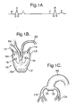
- FIGs. 1A, 1B and 1C a brief description of the normal operation of the human heart be given in order to facilitate an understanding of the present invention.
- the heart 10 shown in Fig. 1B has four chambers, namely the right atrium RA, the right ventricle RV, the left ventricle LV, and the left atrium LA.
- Venous blood returning to the heart flows into the right atrium, then into the right ventricle and passes to the lungs via the pulmonary artery PA.
- the blood picks up oxygen and returns to the left atrium LA, as indicated by the arrow 14. From there, the oxygenated blood passes into the left ventricle, and then into the aorta AO where it starts on its journey through the so-called big circulation around the body.
- the circulation from the right ventricle to the lungs and then to the left atrium is called the minor circulation.
- the operation of the heart is associated with electrical signals, which are shown on the electrocardiogram of Fig. 1A .
- the point P signifies the contraction of the two atriums RA and LA, which pushes blood into the respective ventricles RV and LV via the respective valves 16 and 18, which act as non-return valves.
- the section of the electrocardiogram starting with Q and ending with T is referred to as the systole and represents the ventricle contraction which serves to expel blood from the right ventricle into the pulmonary artery, and from the left ventricle into the aorta.
- the valves 16 and 18 are closed to prevent reverse flow into the right atrium and left atrium.
- the section TQ is referred to as the diastole, meaning the relaxation or expansion of the ventricles.
- the heart is supplied with oxygenated blood via the coronary arteries CA, which branch off from the aorta just upstream of the valves 20, 22, which close to prevent blood returning from the aorta to the left ventricle during the diastolic phase.
- the heart itself a muscle, must be supplied with oxygenated blood to keep the muscles working.
- the heart is supplied with this oxygenated blood via the coronary arteries CA during diastole.
- the valves 20, 22 of the aorta AO are closed and at this time the blood pressure in the aorta causes blood to enter the coronary arteries CA. Accordingly, an increase of the pressure in the aorta AO during diastole favors the coronary arteries.
- one of the important results of the present invention is a small increase in pressure in the aorta during diastole and this has been found to have a profound effect on the operation of the heart muscle.
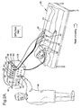
- FIG. 2A shows an illustration of a basic apparatus which has been used for the testing of the present invention and which clearly also represents a perfectly viable apparatus for practicing the invention, although a whole variety of further improvements and developments are possible, as will be described later.
- a patient 24 is shown lying on a bed 26 and is connected to an electrocardioscope 28 via, in this embodiment, three sensing electrodes 30, which enable the electrocardioscope to show the ECG trace 32 for the particular patient 24 on the display 34.
- a signal is extracted corresponding to the repetition frequency of the path R-R of the ECG trace of Fig. 1A . That is to say, this signal represents the frequency at which the patient's heart beats, i.e. his pulse rate.
- This signal is fed to a pulse generator 36 via a line 38 which is not shown in Fig. 2A but which is schematically illustrated in the diagram of Fig. 4 relating to the operation of the apparatus of Fig. 2A .
- the pulse generator 36 delivers a train of biphasic rectangular pulses to the patient 24 via the active electrodes 40, of which four are shown in Fig. 2A .
- the further electrode 42 is a neutral electrode necessary to complete the circuit.
- the train of pulses 44 is triggered once per cycle of a patient's heart and is timed to coincide with the end of the T-phase of the ECG.
- the train of pulses 44 is also shown on the display 34 of the ECG, which enables the operator 46 to see the phase relationship between the train of pulses 44 and the electrocardiogram 34.
- the operator 46 can see whether the train of pulses has the appropriate delay relative to the Q-wave to secure the cardioresonance desired in accordance with the invention.
- the train of pulses is preferably set to start at the end of the T-wave.
- the operator 46 is able to adjust the phase for the start of each train of pulses, i.e. the delay, so that it coincides with the end of the T-wave. This is one manual input into the pulse generator indicated at 48 in Figs. 2A and 4 .
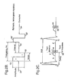
- the basic output of the pulse generator 36 is shown in Fig. 2B .
- the train of pulses comprises a plurality of so-called biphasic, rectangular impulses.
- Each biphasic rectangular impulse has a rectangular positive half pulse 50, and a rectangular negative half pulse 52 immediately following the positive half pulse, so that the impulse width is determined by the width of 50 plus the width of 52.
- the biphasic impulse 50, 52 of Fig. 2B is then followed by an interval and is then followed by a second biphasic impulse indicated as 50', 52' in Fig. 2B .
- the distance between sequential positive half waves 50, 50' of the biphasic pulses determines the pulse repetition frequency of the signal.
- the voltage applied to the electrodes 40 is zero, i.e. the same as the voltage at the neutral electrode 42, so that no stimulation of the patient occurs.
- This zero voltage is indicated by 54 in the diagram of Fig. 2B . It will be noted that instead of applying voltages to the electrodes, currents can be applied to them in which case the references above to voltages should be regarded as references to currents.
- each train of biphasic rectangular pulses is timed to start at the end of the T-phase of the ECG, i.e. at points 56 in the diagram of Fig. 2C which shows an enlarged section of an ECG trace with the impulse trains 44 superimposed on it.
- the pulse repetition frequency of the biphasic rectangular pulses of each train is selected so that ten such pulses occur within the train duration.
- the train duration is usually selected to correspond to a time equivalent to from 10 to 25 % of the TQ diastole duration of a human being undergoing treatment.
- a typical value of the train duration will amount to 10 % of the total duration of the heart beat, i.e. the R-R distance.
- the pulse repetition frequency delivered by the pulse generator 36 would, in this example, be ten pulses in one tenth of the duration of a heart beat, which might typically be equivalent to 1 second, thus resulting in a pulse repetition frequency of the individual pulses of the trains of 100 Hz.
- the amplitude of the output signal of the pulse generator 36 i.e. as applied to the electrodes 40, can vary from a positive amplitude 50 of plus 20 V to a negative amplitude 52 of minus 20 V.
- the relationship between the pulse width and the pulse interval of each train of pulses determines the total energy input into the muscles stimulated via the electrodes 40, 42. While a ratio of 1:10 has been found effective, this ratio can be varied substantially and indeed an interval is not absolutely essential. Generally speaking, with all patients a threshold is reached, depending on the pulse amplitude and the ratio of the pulse width to the interval, at which involuntary contractions of the muscle are apparent to a trained observer and the apparatus will usually be operated with amplitudes and ratios of the pulse width to pulse interval at levels at which apparent involuntary muscular contractions do occur, i.e. above the threshold value.
- biphasic rectangular pulses of the kind described above have been found to be satisfactory and currently represent the preferred type of pulses, they are by no means the only possibility.
- the pulses delivered by the pulse generator will be biphasic in the sense that they have some positive going signal component and some negative going signal component.
- the negative half wave is of the same size and shape as the positive half wave.
- the positive half wave could be of different amplitude and width from the amplitude and width of the negative half wave.
- the pulses to be rectangular pulses. They could be sinusoidal or they could have some other shape if desired.
- a preferred embodiment of the invention provides the operator 46 with seven different parameters which he can set during the treatment of a patient.
- the first of these is the delay or impulse delay, which, as shown in Fig. 2C , is the time difference between the Q wave end of a QRS heart signal and the effective start of the impulses, i.e. the start of the train or burst of impulses which commences at the end of the T-wave.
- the operator 46 has the possibility of adjusting this delay at 48, for example, by varying a potentiometer which determines the delay.
- the effect of the pulses is to unload the heart. This manifests itself by a reduction of the pulse rate, i.e. of the frequency of the heart beat. This means that the time between successive R peaks of the ECG trace increases. Not only does R-R increase, but the distance from Q to the end of the T wave also increases because it stands in a known relationship to the time interval R-R. Thus, if the delay were fixed, the start of the train of pulses 44 would not always coincide with the end of the T-wave due to the change in the pulse rate. Accordingly, with the apparatus of Fig.
- the operator 46 is able to adjust the delay at 48 to ensure that the train of pulses is always initiated at the end of the T-wave.
- the patient's pulse rate it is entirely usual when using the apparatus of the present invention, for the patient's pulse rate to drop from, say, 72 to 62 over a ten minute period, so that the operator 46 has plenty of time to effect the necessary adjustment.
- the duration of the train of pulses applied to the patient after the end of each T-wave is defined as the time between the start and the end of the impulses within a train or burst of impulses. This possibility of variation is indicated in Fig. 4 by the reference numeral 58.
- the train itself is the package of electric impulses which are repeated one after the other for the time defined by the duration of the train.
- the number of electric impulses in each train can be varied by varying the output frequency of the pulse generator, i.e. the pulse repetition frequency of the pulses in each train of pulses, i.e. the number of pulses that are repeated per second if the train of pulses were to be one second long.
- the duration of the train determines how long the stimulation with a given frequency is repeated, i.e. how many impulses are effectively delivered within one heart cycle. This frequency and the duration of the train can be varied by the operator 46 at the input 60 in the example of Fig. 2A and Fig. 4 .
- the other variable which can be readily changed by the operator 46 in the embodiment of Figs. 2A and 4 is the amplitude of the biphasic rectangular impulses, i.e. the maximum difference between the peak value of the positive half cycle 50 and the peak value of the negative half cycle 52, as shown in Fig. 2B .
- This possibility of adjustment is indicated at 62 in Fig. 4 .
- the amplitude is normally measured as a potential difference in volts.
- Figs. 2A and 4 there are three further parameters of the pulses which are fixed, i.e. cannot in this embodiment be varied by the operator 46.
- the first of these parameters is pulse width, i.e. the time before the start and end of an electric impulse, as shown in Fig. 2B .
- the pulse width is selected in the example of Figs. 2A and 4 , so that the interval at a pulse repetition frequency of 100 Hz is ten times as long as the pulse width. That is to say by fixing the pulse width the interval will automatically vary as the pulse repetition frequency is varied.
- the pulse width is made variable, as it is in some other embodiments, then varying the pulse width automatically results in the interval shown in Fig. 2B varying, on the assumption that the repetition frequency of the pulses of the train of pulses does not change.
- Box 64 in Fig. 4 relates to the input at which the fixed value of the pulse width is selected.
- the further boxes 66, 68 in Fig. 4 represent two further parameters of the output of the pulse generator, which in the apparatus of Fig. 2A and Fig. 4 are fixed and not readily variable by the operator 46.
- Box 66 relates to the impulse form, i.e. the geometric form of the electric impulse resulting when the amplitude of the electric impulse is displayed over the entire impulse width. In the present example this is a biphasic rectangular pulse but it could have different shapes, for example sinusoidal or saw-toothed.
- Box 68 refers to the possibility of changing the impulse mode which relates to the alternating mode of how impulse forms are repeated between electric positive and electric negative phase of impulses.
- the impulse mode is clearly biphasic, with positive and negative, but otherwise identical electric impulses alternating one after the other. This mode switch would, however, allow the operator to select some other mode, for example two positive half pulses followed by one negative half pulse.
- the electrode 42 is a neutral electrode and it is only necessary to provide one such neutral electrode.
- more than one neutral electrode can be used when different areas of the body are treated, in order to allow a neutral electrode to be in the vicinity of each active electrode or each group of active electrodes.
- the stimulating impulses to the different active electrodes 40 in sequence it is possible to ensure that the muscle groups affected by the applied impulses do not become tired.
- the minimum number of active electrodes for sequencing is two.
- Fig. 4 also shows with a series of boxes how the stimulation input to the patient from the pulse generator affects the body.
- Box 70 indicates that the stimulation can be direct stimulation or neuromuscular stimulation which is more usual. As noted above, the stimulation aspect will be described later in more detail.
- Box 72 shows that the stimulation can be applied either to skeletal muscles or to smooth muscles.
- the effect of applying the stimulation to skeletal or smooth muscles is in both cases to produce a pressure pulsation in a local blood vessel of the peripheral vascular system indicated by the box 74.
- This local pressure fluctuation propagates via the blood, essentially an incompressible liquid indicated by box 76, to the heart indicated by box 78.
- the pulses are timed correctly and applied in accordance with the teaching of the present invention, then they have been found to have a significant effect in reducing the heart load, which itself has an effect on the body of the patient indicated by box 80. This effect is picked up by the electrodes 30 of the electrocardioscope.
- a signal corresponding to the pulse rate for example the R-R signal, is then passed on to the pulse generator and triggers the generation of the biphasic rectangular pulses of the individual pulse trains.
- the ECG wave form 82 is shown on the display 34 of the electrocardioscope as is the output signal of the pulse generator, as shown by the lines 82 and 84 in Fig. 4 .
- the operator 46 has the ability to vary the impulse delay to ensure that each train of pulses starts at the end of the T-wave of the electrocardiogram or at the position deemed optimal in a particular case.
- the operator 46 is able to see, by observing the display 34, how the patient's heart rate drops in response to the treatment and is able to vary the impulse delay accordingly.
- the impulse delay is conceptually considered as measured from the end of the Q-wave, it can be measured from another datum if required. It is in fact simpler to measure the impulse delay from the R peaks because these are larger signals which also occur at clearly defined times.
- Fig. 3 gives a graphic representation of the effect of the treatment with the apparatus of the invention.
- the topmost curve 86 shows several peaks of an ECG wave form and is divided basically into three sections A, B and C.
- Section A shows a patient's cardiac rhythm in a normal situation, i.e. without stimulation.
- Section B shows the cardiac rhythm for the same patient at the start of stimulation and section C shows the cardiac rhythm during continued stimulation.
- This division into sections A, B, C also applies to the further curves 88 and 90.
- section B shows the first train of impulses 44 which starts after the end of the T-wave and lasts for about 15 % of the T-Q path. This same wave form repeats in phase C and continues repeating until the stimulation is terminated.
- the effect of this stimulation is to produce a significant reduction in the patient's heart rate so that the length between successive R positions of the ECG lengthens in the course of time. It will be noted that the R-R pattern in section C is longer than in section A, by a length labeled "b" as shown in curve 90 in Fig. 3 .
- Curve 88 shows the modulation of the muscular power resulting from the trains of electrical impulses such as 44.
- phase A of line 88 there is no stimulation and accordingly the line is a straight line.
- the first stimulation occurs in the section B and results in a stimulation of a muscle which affects the peripheral vascular system.
- the muscle contraction 3 starts at the start of the train of pulses 44 and tends to reach its maximum contraction at the end of the train of pulses and then relaxes over a time period slightly longer than the train duration.
- the train of pulses 44 contains a plurality of stimulating electrical impulses but results in a simple muscular contraction. This muscular contraction 3 produces a pressure pulsation in the patient's peripheral vascular system which propagates back to the patient's heart.
- the curve 90 which is in fact a composite curve showing the pressure in the aorta and the left ventricular pressure.
- the left ventricular pressure starts from a base line value 92 and increases smoothly into a rounded peak 94, which has a value above the base line value 92 from the start of the Q wave until just after the end of the T-wave.
- a curve 96 for the pressure in the aorta is superimposed on this curve.
- valves 20, 22 in Fig. 1C open and the pressure in the left ventricle is communicated directly into the aorta so that the pressure in the aorta rises at the same rate and with the same value as the pressure in the left ventricle until the end of the T-wave is reached, i.e. until the point 100 in Fig. 3 , where the valves 20, 22 close again and the pressure in the aorta gradually sinks as the blood in it moves through the arteries of the human body.
- the valves 20, 22 open again and the cycle repeats.
- the effect of the muscular contraction is to modulate the pressure in the aorta by a pressure wave traveling back to the aorta, from the peripheral blood vessel pulsation induced by the muscle contraction, so that in phase B it is slightly higher - shown as a visible hump - in the region labeled 2 than the corresponding value in phase A of curve 96.
- the pressure in the aorta sinks to lower values than were present in the corresponding section of the pressure curve in phase A.
- the peak 94" of the left ventricular pressure has also reduced relative to the peak value 94 in phase A.
- the hump 2 in the pressure in the aorta in diastole results in increased coronary circulation, i.e. more blood and more oxygen is being supplied to the heart muscles, resulting in more energy being made available to the heart.
- This causes the pulse rate to reduce so that the duration of each heart beat increases from the value a before stimulation by the amount b to the value a + b after prolonged stimulation.
- the typical measured reduction with various probates is about 10 pulses per minute in the rest mode, for example 70 down to 60, or up to 30 or more at a high pulse rate, for example from 140 to 110, because of an increase of the DPTI/TTI ratio (diastolic blood pressure time index/time tension index).
- the reduction indicated by 4 from the peak value 94 in phase A to the peak value 94" in the phase C represents a fall in the systolic pressure in the left ventricle and thus reducing left ventricular wall tension.
- the pre-systolic blood pressure i.e. the pressure at the points 98, 98', 98" in Fig. 3 seems to reduce by about -5 mm Hg for a probate with normal blood pressure of 120/60. Extremely beneficial is the fact that with patients with blood pressure which is too high the reduction is far more pronounced, although the reduction in the heart rate for such patients tends to be less than for normal patients.
- cardioresonance electrostimulation of the invention not only results in a lower systolic pressure but also a steeper pressure increase in the systole, which can also be seen from curve 90 in phase C of Fig. 3 .
- DPTI increases by some + 10 to 15 % depending on probates resulting from the hump in the blood pressure increase in diastole, reduced heart pulse rate and corrected by the difference from reduced pre-systolic blood pressure, assuming probates with normal blood pressure.
- TTI decreases by some 4 to 5 %, resulting from lower pre-systolic blood pressure corrected by the steeper pressure increase in systole (as shown at 7 in Fig. 3 ).
- the DPTI / TTI ratio consequently increases by some 15 to 20 % depending on probates for those having normal blood pressure.
- the typical heart load reduction is some 10 to 25 % or more depending on the probates and their physical condition, which results from lower heart pulse rate and reduced systolic blood pressure and lower presystolic pressure.
- myocardial contractivity is improved, coronary blood circulation increased and ischemia reduced.
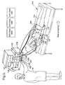
- FIG. 5 a similar apparatus can be seen to that shown in Fig. 2A , but with various modifications. Because of the similarity to the apparatus of Fig. 2A , the same basic reference numerals will be used to identify the items of apparatus in Fig. 5 and in Fig. 6 as were used in connection with Fig. 2A and Fig. 4 , but increased by 100 for the sake of clear differentiation. Only those items where a significant difference is present will be specifically described. All items not specifically described with reference to Figs. 5 and 6 but shown in the drawing will be understood to have the same function and operation as the correspondingly numbered elements in Figs. 2A and 4 . The description given to these elements in Figs. 2A and 4 will be understood to apply to Figs. 5 and 6 .
- the general arrangement of the patient 124 on the bed 126 is the same as before.
- the first significant difference in the embodiment of Figs. 5 and 6 is the fact that the pulse generator 136 has been incorporated into the housing of the electrocardioscope 128. Despite this modification the arrangements of the electrodes 140 and 142 is the same as before and these are fed by the pulse generator 136 in just the same way as described above in relation to Figs. 2A and 4 .
- the electrocardioscope 128 has three sensor electrodes 130 connected to the patient in the heart region. It should be noted here that different electrocardioscopes have different numbers of electrodes, depending on the precise measurements that are required. For the purpose of the present invention a simple measurement is sufficient.
- the operator is again schematically indicated at 146.
- FIG. 5 Another significant difference in Fig. 5 is the additional provision of a blood pressure meter 131 which is connected to a blood pressure measuring cuff 133 via the usual lines 135 (only one shown).
- a measurement of the patient's blood pressure is also effected.
- the blood pressure meter 131 has a display 137 on which the patient's blood pressure can be displayed, either as a curve or simply as different values for the systolic and diastolic pressure.
- the layout of the pulse generator 136 is essentially the same as for the pulse generator of the embodiment of Figs. 2A and 4 .
- the same seven values for the pulses output by the pulse generator can be set as in the embodiment of Figs. 2A and 4 .
- all of the parameters are variable and indeed either by the operator 146 or automatically.
- the operator is able to effect the individual settings via respective inputs 148' to 168'.
- all these settings can be effected electronically via a suitable external program interface 141, which communicates with an input program interface 143 connected to the pulse generator, which is preferably realized as a chip.
- the communication between the external interface 141 and the internal interface 143 can be direct, i.e. by hard wiring, or can be indirect, for example by way of an infrared transmitter or the like.
- the pulse generator i.e. the control unit controlling the operation of the pulse generator is programmed to either detect the end of each T-wave, or to calculate the time position of the end of each T-wave from the data provided by the electrocardioscope and to automatically control the triggering of the pulse train so that each train is automatically triggered at the end of each T-wave.
- the pulse generator i.e. the control unit controlling the operation of the pulse generator is programmed to either detect the end of each T-wave, or to calculate the time position of the end of each T-wave from the data provided by the electrocardioscope and to automatically control the triggering of the pulse train so that each train is automatically triggered at the end of each T-wave.
- Such synchronized operation of a pulse generator is well known generally in the electronic arts, for example in transmitters which respond to acknowledge an incoming signal, and can thus readily be realized by a person skilled in the art.
- the apparatus shown in Fig. 6 is provided with a data storage system 151 including a memory which is able to store any desired parameters or measured values of the apparatus.
- the storage system can be designed to store, optionally in compressed form, full wave ECGs over a period of time, for example an hour, a day or a week, and also data relating to the patient's blood pressure in the same intervals.
- the external program interface can also be used to read out the data contained in the data storage system.
- This safety cutout is to analyze the measured parameters and to compare them with established parameters so that the treatment can be automatically discontinued if the measured parameters show any undesirable deviation from the desired values.
- limiting values for critical parameters such as the pulse rate and the systolic or diastolic pressure can be registered and stored in the safety cutout, or in a memory associated with the apparatus to which the safety cutout has access.
- the safety cutout receives values corresponding to the pulse rate and the systolic and diastolic blood pressure and checks whether any of these values are higher or lower than the limit values set before the start of electrostimulation. Should any of the values rise above the limit values, or rise above the limit values by a significant amount, then the safety cutout will be programmed to operate to alert the operator 146 and/or to shut off the pulse generator if appropriate.
- the limit values can also be set to be the initial values before electrostimulation.
- the safety cutout could also be designed to trigger its function, for example to cutout stimulation or to signal an alarm, if statistical deviations of the input signal are detected over a certain time period or when heart arrythmia are detected.
- the safety cutout can also compare the patient's pulse rate and blood pressure values with stored lower threshold values, which are set at a safety level, below which they should not fall. Should the measured values during electrostimulation fall below the minimum safety values, then again the operator can be alerted and/or the system can be automatically shut down.
- the safety cutout for example using the external and internal program interfaces 141 and 143 with appropriate values from a normal, healthy person or from a person suffering from the same typical problem as the patient undergoing treatment.
- Figs. 2A and 4 and Figs. 5 and 6 are clearly used for the treatment of patients in a reclining state.
- the invention is, however, quite capable of being used by patients going about their normal daily lives.
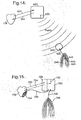
- FIG. 7 shows a patient equipped with a suitable apparatus for carrying out the treatment throughout the course of a normal day while going about his normal daily life, or during sleep.
- the apparatus of Fig. 7 comprises an elastic chest bandage which includes two heart pulse rate sensors 253 and a wireless transmission unit 255 for transmitting a signal corresponding to the heart pulse rate to a receiver 257 incorporated into an elastic waistband, for example of a pair of pants 267.
- the receiver 257 forms part of an electrostimulation unit comprising a pulse generator 236 with an inbuilt battery.
- the pulse generator 236 is again connected via wires to corresponding electrodes 240 and 242, of which only one active electrode 240 and one neutral electrode 242 are shown in Fig. 7 . It will, however, be understood that a plurality of active electrodes 240 can be provided as aforesaid.
- a heart pulse rate sensor with a radiotransmitter unit of the kind used here is available for use by athletes under the trade name "Polar" (registered trade mark).
- the "Polar” transmitter two electrodes are provided to detect an electrical signal on the wearer's skin.
- the electrodes are mounted on a sealed transmitter that is attached to the patient's chest by way of the elastic chest bandage.
- the Polar transmitter detects the voltage differential on the skin during every heartbeat and sends the signal continuously and wirelessly using electromagnetic fields to a wrist receiver.
- the receiver is modified, not to be in a wrist watch, but instead built into a waistband, as aforesaid.
- the method used in the Polar transmitter is based on ultralow power consumption, which is guaranteed with the unique insertion mode at electronic module and carefully designed and tested circuitry to pick up the electrical signal of the heart.
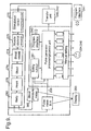
- the operation of the apparatus of Fig. 7 is basically the same as the operation of the apparatus of Fig. 4 , as can be seen with reference to the block circuit diagram of Fig. 8 .
- a display 263 is provided which can take the form of a small liquid crystal display mounted, for example, on the waistband of the pants.
- the display 263 would normally display just the patient's pulse rate, but could optionally display any other desired information, for example the settings of the pulse generator.
- the settings of the pulse generator can be controlled by the patient himself 224 or by an operator 246 if the apparatus is fitted to a patient in a surgery, for example.
- the patient 224 or the operator 246 can control the seven variable settings - or only some of them if the others are fixed - via corresponding manual inputs 248', 258', 260', 262', 264', 266' and 268', which could, for example, be realized as keys on a small keyboard.
- a program interface 243 can be provided which can be used to program the pulse generator by a separate input program program interface 243, as in the apparatus of Fig. 6 .
- the apparatus of the present invention is provided with a simple pulse rate meter in order to deliver an R-R signal which is quite sufficient to control the pulse generator 236 to provide the correct stimulating pulses at the correct time. It is not necessary to actually measure the end of the T-wave to control the delay of the pulses, because the QT path is known to have a well-defined relationship with the R-R path and thus the end of the T-wave can easily be calculated from the signals generated by the pulse rate meter.
- the signals from the pulse meter it is not essential for the signals from the pulse meter to be transmitted by radio to the pulse generator 236.
- the signal could easily be transmitted using small wires if desired.
- pulse rate measuring sensors instruments available which are very small and unobtrusive and can be used at a location other than immediately in the vicinity of the patient's heart. Any of these known pulse rate measuring sensors can be used for the purposes of the present teaching.
- Figs. 7 and 8 there is also a safety cutout 261, but here the safety cutout only responds to the patient's heart rate, i.e.
- FIG. 9 A possible modification of the apparatus of Fig. 7 is shown in Fig. 9 .
- the same basic reference numerals are used as in the apparatus of Fig. 8 , but prefixed with the number 300 rather than 200.
- a blood pressure meter 365 which can also pick up a suitable signal from a patient's body and enable this signal to be shown on the display 363.
- a blood pressure meter it can also be connected to the pulse generator as a variable input signal in parallel to the pulse rate R-R.
- the output signal of the blood pressure meter can be the only input signal to the pulse generator, so that the apparatus is also able to operate without a separate pulse rate measurement.
- the blood pressure meter can also be connected to the safety cutout 361, so that an alarm is given should the patient's blood pressure rise or fall beyond safe limits.
- the controller of the pulse generator can use either one of the single input signals as the control parameter. I.e. the controller can use either the heart pulse rate signal 238, see e.g. Fig. 8 , or the systolic blood pressure signal included in signal 365, as the control parameter. Alternatively the controller of the pulse generator can use a combination of the two input signals, i.e. the heart pulse rate signal 238 and the systolic blood pressure signal in 365 in parallel, see e.g. Fig. 9 .
- the controller uses as the control parameter a factor resulting from the heart pulse rate signal multiplied by a factor relating to the systolic blood pressure - then the multiplied factor is proportional to the heart loading.
- the first measurement of the input signal or signals entering the controller when it is started, i.e. the value of the input signal or signals before the start of the stimulation will determine the factors with the value of 1. Every deviation of the factors will be measured by the controller relative to these starting values having the value of 1, when comparing the effective result achieved versus the intended reduction of the multiplied factors, which is proportional to the reduction of the heart load being aimed for.
- the controller aims to minimize the multiplied factors of the two input signals (heart pulse rate and systolic blood pressure - being proportional to the heart load directly) by varying one or more of the seven variable parameters of the pulse generator, numbered 248 to 268 in Fig. 9 , according to algorithms which are programmed into the microchip forming the control unit of the pulse generator 236. If the two input signals, heart pulse rate and systolic blood pressure are not measured at the same intervals and / or not with the same timing relative to the QRS complex of the heart, the controller will always use the latest valid factor for each input signal for the multiplication.
- the controller aims to minimize the selected input signal - either the heart pulse rate or the systolic blood pressure - by varying one or more of the seven variable parameters of the pulse generator, numbered 248 to 268 in Fig. 8 , according to algorithms which are programmed into the microchip.”
- the safety cutout In the case of a portable apparatus it would be advisable for the safety cutout to be provided with an alarm so that the patient is alerted to a dangerous condition and look at the display and switch off the pulse generator or stop whatever labor or exercise he is undertaking.
- the portable apparatus of Figs. 7 , 8 and 9 is particularly suitable for all categories of treatment described in the introduction to the specification and in particular for lipolysis and body shaping treatment and helping athletes improve their performance, in training various muscle groups of the body and in general improvement of a person's condition and physique. If particular muscle groups are to be trained, for example muscles concerned with the urinary tract or the sphincter muscle, then special electrodes need to be placed accordingly, so that the required local stimulation takes place.
- Fig. 10 is a schematic diagram illustrating how the apparatus of the present invention works on the human body.
- Fig. 10 is basically a combination of elements of the diagram of Fig. 4 with elements of the diagrams of Fig. 1 . Accordingly, the same reference numerals will be used.
- Fig. 10 shows that electrostimulation is applied directly or as neuromuscular stimulation 70 to either skeletal or smooth muscles that are indicated by box 72. These muscles act on the peripheral vascular system of the patient to cause peripheral blood vessel pulsation indicated by box 74. This is transmitted through the blood in the patient's body as a pressure waveback to the aorta AO, where a corresponding pressure increase arises.
- the pressure pulsations affect the circulation of the blood in the patient's body indicated by 70 and in particular increase the coronary circulation through the coronary arteries CA.
- the better pumping of the heart 10 results in an affect on the aorta, hence the double arrows between the box AO for the aorta and the box 70 for the patient's blood system.
- the improved blood flow through the aorta also has an effect on the peripheral vascular system, since the blood flow there is improved as well.
- Clearly improved blood flow into the peripheral vascular system results in increased blood flow back through the veins 71 to the heart, as indicated by the arrow 12 in Figs. 1B and 10 .
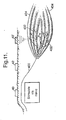
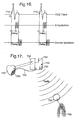
- Fig. 11 now explains various different concepts of neuromuscular electrostimulation. More specifically, Fig. 11 shows a bundle of nerves 400 which pass to muscle fibers 402 of a skeletal muscle 404.
- the neutral electrode is labeled 42.
- Fig. 11 shows two different active electrodes 40 and 40'.
- the active electrode 40 is positioned close to a location where the bundle of nerves 400 is fairly close to the surface of the skin.
- the active electrode 40 stimulates the bundle of nerves 400.
- By stimulating the bundle of nerves 400 it stimulates the muscle fibers 402 in the muscle 404, to which the bundle of nerves 400 leads. This is a typical example of neuromuscular electrostimulation.
- the active electrode 40' is not positioned close to a bundle of nerves 400, but rather in the immediate proximity to the muscle 404, so that it stimulates the muscle fibers 402 in the muscle 404 directly.
- This is called direct stimulation.
- direct stimulation requires more power and higher voltages or currents than neuromuscular stimulation.
- Direct stimulation is, however, particularly important in the rehabilitation of patients such as paraplegics, where a bundle of nerves, such as 400, may have been cut for some reason or other, for example due to an accident.
- a bundle of nerves such as 400 passes very close to the surface of the skin, for example in the back, close to the spine, so that a type of nerve stimulation is possible referred to as transcutaneous electrical nerve stimulation (TENS), this being a special case of neuromuscular stimulation.
- TENS transcutaneous electrical nerve stimulation
- Fig. 12 shows a system in which electrostimulation of an acupuncture electrode 562 is used.
- the output of the pulse generator 136 is applied directly or via a suitable amplifier 560 to an acupuncture needle 562 in the patient's arm.
- the acupuncture amplifier 560 effectively a generator of electrostimulation signals, causes electrostimulation of the acupuncture needle 562, which affects the patient's skin 554.
- Fig. 12 could be executed using a portable pulse generator in a similar way to the embodiment of Fig 7 . I.e. similar small equipment and possibly radio transmission for the signals from the sensor electrode(s) can be used in place of the stationary equipment shown.
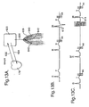
- Figs. 13 and 14 show that the present invention can also be used with a known cardiostimulator, for example in the form of a pacemaker or defibrillator.
- Figs. 13A and 14 it is helpful to consider the function of a pacemaker with respect to Fig. 13B and the function of a defibrillator with respect to Fig. 13C .
- Fig. 13B shows the typical ECG trace of a patient fitted with a pacemaker.
- the typical pacemaker patient has an irregular heart beat, which for example means that the heart misses a beat every so often.
- the pacemaker senses a missing heart beat and immediately triggers a stimulation signal such as 612 which causes the heart to beat just a fraction later than it would have done had the heart beat occurred at the correct time.
- a stimulation signal such as 612 which causes the heart to beat just a fraction later than it would have done had the heart beat occurred at the correct time.
- the pacemaker effectively measures an electrocardiogram and in any event contains all the information on the repetition frequency of the R peaks necessary to trigger a pulse generator to apply stimulating signals in the counterpulsation mode in accordance with the invention.
- Fig. 13B shows such trains of stimulating impulses 44 at the end of the T-wave.
- the stimulating pulses are applied as shown in Fig. 13A to a muscle close to the patient's heart, since, in accordance with the invention, it does not matter which muscles of the peripheral vascular system are chosen to provide pressure pulsations in the peripheral vascular system which affect the heart.
- Fig. 13C shows the situation with a patient suffering from fibrillation.
- the first two heart beats are normal, but then the regular electrical wave, which regulates the heart beat, goes into fibrillation, i.e. the patient's heart stops beating regularly and the electrical wave fluctuates wildly.
- a defibrillator follows the ECG trace and recognized when a heart beat is missed and fibrillation occurs. To get the heart beating normally again, the defibrillator applies a significantly higher electrical signal 614 to the heart than is usual and it can be seen that the heart starts to beat again normally following defibrillation.
- a defibrillator which is another form of cardiostimulator, also follows the ECG trace of the patient to which it is fitted and thus has available all the information on the repetition frequency of the R-R peaks which is necessary for calculating the end of the T-wave and applying stimulating pulses to the patient's peripheral vascular system in accordance with the present invention. Accordingly, it is possible to take a standard cardiostimulator, for example a pacemaker or a defibrillator, and to add to it circuitry, for example in accordance with Fig. 8 , to enable stimulating pulses to be applied to the patient's peripheral vascular system.
- a standard cardiostimulator for example a pacemaker or a defibrillator
- Fig. 13A shows such a combination.
- the patient's heart 178 is schematically illustrated and the cardiostimulator is indicated by reference numeral 620.
- the arrow 622 represents the pacemaker following the electrical signals of the heart and the arrow 624 represents the trigger pulse sent back to the heart by the pacemaker 620 when a missing beat is sensed.
- the pacemaker 620 has been supplemented with the circuitry of Fig. 8 in a miniaturized form and also has output leads 626 which lead to respective electrodes 640 and 642 provided on a muscle 628 which may be close to the heart, so that the leads do not have to extend over a substantial distance to the patient's body.
- the modified cardiostimulator 620 of Fig. 13A can find the timing of the R-R-peaks from the ECG trace, can calculate the end of the T-wave using the known relationship between the Q-T and R-R pulse and can time stimulating pulses 44, so that they are initiated at the end of the T-wave to obtain the beneficial effects of the present invention.
- a defibrillator in this case the cardiostimulator 620 in a combination of a defibrillator with the apparatus of the for example Fig. 8 of the present invention.
- the apparatus of Fig. 13A will be used for long term treatment, it is reasonable to use a plurality of active electrodes 640 (at least two) for the reasons given above. This also applies to the embodiment of Fig. 14 .
- Fig. 14 illustrates another way of realizing the present invention in combination with a cardiostimulator 620 which again can, for example, be a pacemaker or a defibrillator.
- the cardiostimulator 620 is supplemented by a radio transmitter 630 and this transmitter 630 transmits radio waves through the patient's body containing information on the R-R peaks or the end of the T-wave to a further apparatus 632 which is constructed in accordance with the invention, for example in accordance with Fig. 8 , and is located at a different position in or on the patient's body.
- the apparatus 632 would include its own battery and again will transmit the required stimulating pulses to electrodes 640 and 642 affecting a muscle 628 which again produces pulses in the patient's peripheral vascular system.
- the battery required for an apparatus such as 632 can readily be of the same size and type as that used for a pacemaker. Since the apparatus of the invention, for example in accordance with Fig. 8 , can easily be miniaturized using modern semiconductor chip technology, the whole implanted apparatus 632 certainly need be no larger than a typical cardiostimulator and can indeed be smaller.
- the apparatus 632 and the associated electrodes can either be implanted in the patient's body or provided externally thereof.
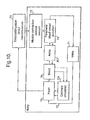
- Fig. 15 there is shown another way of realizing the present invention in combination with a cardiostimulator 750, which is here realized as a cardiomyostimulator modified to additionally satisfy the present invention.
- the cardiomyostimulator 750 comprises a cardiac pacemaker 720, which communicates with the heart 178 so that it receives electrical signals of the heart 178, as symbolized by the arrow 722, and sends trigger pulses back to the heart 178, as symbolized by the arrow 724.
- the cardiomyostimulator 750 includes, as known per se, a programmable divider 752 which operates to send a burst of electrical pulses beginning typically at the end of the R-wave and ending typically at the end of the T-wave to a muscle 754 wrapped around the heart via leads schematically illustrated by the line 756.
- this muscle 754 which has to be implanted by a surgical technique, is stimulated in the simpulsation mode.
- the programmable divider 752 is, however, programmed to trigger a further train of impulses which begins exactly at the end of the T-wave and to send these trains of pulses via leads 726 to any desired skeletal or smooth muscle 728, other than a heart muscle, so that this muscle is stimulated to contract in the counter-pulsation mode, thus affecting the patient's peripheral vascular system and causing cardioresonance in accordance with the invention.
- the cardiac pacemaker 720 consists of a sensing amplifier which monitors the intrinsic heart rate as symbolized by the arrow 722 and has an output stage which paces the heart, as symbolized by the arrow 724, as soon as the heart rate drops below a programmed value.
- a cardiac event can be sensed or initiated by the device as in a synchronized pacemaker.
- the cardiac pacemaker 720 triggers a synchronization circuit (not shown but known per se).
- the trigger signals are processed through programmable divider which allows for different heart/wrapped around muscle contraction ratios within the heart muscle conglomerate (178 + 754).
- a delay is then initiated after which the myostimulator is enabled, sending a burst of pulses via leads 756 to the wrapped around muscle 754.
- the programmable divider of the synchronization circuit 752 then also produces a train of pulses which are applied to electrodes provided at the muscle 728.
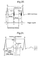
- Fig. 22 The relationship between the pulses applied in the simpulsation mode to the wrapped around muscle 754 and the pulses which are applied to the muscle 728 in the counterpulsation mode can be seen from Fig. 22 in relationship to the ECG trace shown there. This drawing also indicates the synchronization pulse 712 associated with the pacemaker function.
- Fig. 17 is closely similar to the arrangement of Fig. 15 , but here the cardiomyosimulator 750 includes a wireless transmitter 730, which transmits wireless signals to the receiver 732 at or close to the muscle 728. There they are used to trigger stimulating pulses for application to the muscle 728, in similar manner to the embodiment of Fig. 14 .
- the actual pulse generator is incorporated in the cardiostimulator and simply triggers stimulating pulses the power source incorporated in the receiver for application to the muscle 628 or 728 respectively.
- the respective receiver 632 or 732 could also be a part of or associated with a pulse generator located directly at the respective muscle 628 or 728, in which case the signals transmitted to the receiver are trigger signals for the pulse generator and indeed with or without the relevant delay.
- the simpulsation of the heart muscle conglomerate (178 + 754) assists the heart pumping function and is immediately followed by the counterpulsation of the peripheral muscle 728, which leads to increased coronary flow, oxygenation of the heart and a reduction in the heart loading.
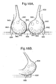
- Figs. 18A and 18B there can be seen a practical realization of the invention in the form of a brassiere 800 provided with sensor electrodes 830 designed to produce a heart pulse rate signal and to communicate this signal to a pulse generator 836 incorporated between the two cups of the brassiere in the strap connecting them. It is stressed that the pulse generator 836 can be readily realized as a small chip.
- the cups of the brassiere are equipped with neutral electrodes 842 and active electrodes 840 in order to apply trains of stimulating impulses produced by the pulse generator 836 to the various positions on the patient's breasts via the active electrodes 840 and neutral electrodes 842, in similar manner to that discussed previously with reference to the embodiment of Fig. 2A .
- the electrical power source for the brassiere 800 can either be a small battery incorporated on the brassiere at a suitable position, for example at the point at which the two back straps meet, so as not to cause discomfort to the wearer, or it can be an external battery carried, for example, in a pocket or belt worn by the patient, which is connected by two discrete leads to the pulse generator 836 and the sensors 836. Also not shown in the drawing are the leads between the sensors 830 and the pulse generator 836 and the leads between the pulse generator 836 and the active and neutral electrodes 840, 842. It will, however, be understood that these leads can be made as very fine wires which are hardly perceptible. Although some wearers of such apparatus may not like the idea of radiotransmission signals close to their heart, it is also perfectly conceivable for the signals sent from the sensor(s) 830 to the pulse generator 836 to be transmitted as wireless signals rather than by wire.
- the electrodes 840 and 842 are preferably worked into the brassiere so that they have contact with the skin of the wearers' breasts. They are preferably detachable and replaceable for hygienic reasons and to facilitate washing. The position of the electrodes is selected so that they have optimum positions to firm the breast muscle and tissue having regard to the design of the brassiere and its size.
- Figs. 19A , 19B and 19C show the realization of the invention in combination with a seat which may be a vehicle seat, such as an aircraft seat or a car seat or it may be a chair used in the patient's home, at work, in a clinic or in a cinema or elsewhere.
- a seat which may be a vehicle seat, such as an aircraft seat or a car seat or it may be a chair used in the patient's home, at work, in a clinic or in a cinema or elsewhere.
- the seat 900 comprises a backrest 901 and a seat base 903.
- two belts are provided, namely a belt 906 resembling the elastic chest bandage of Fig. 7 , but incorporated into the backrest 901 and having at least one heart pulse rate sensor 953 and a wireless transmission unit 955 for transmitting a signal corresponding to the heart pulse rate to a receiver 957 incorporated into a pulse generator 956.
- the pulse generator 956 may have an inbuilt battery or may be connected to another source of electricity provided in the vehicle or in the building in which the seat is located.
- flat inflatable pressure pads 902 are provided and can be incorporated into the seat base 903 and/or into the backrest 901 and/or into a stomach or waist belt 905.
- the seat 900 it is important that the piping problems are solved.
- the best analogy is a cable duct that can be opened at any location to allow the cables to come out so as to avoid loose cables, the opening being as small as possible, as in the proposed arrangement, where the opening is defined by the overlapping flaps.
- the seat could have any number of built-in flexible pipes 907 arranged beneath two overlapping flaps.
- Pressure pads such as 902 can be attached via their own Velcro-attachments at any location close to a piping run so that a minimum of loose piping extends between the electrodes and the belt 905.
- the seat can be any seat in which a person usually sits for a long period of time, such as in a car, an aircraft, in the office etc.
- Figs. 19A to 19C show a particularly flexible design of the seat 900 incorporating the present invention.
- the backrest 901 and the seat base 903 both comprise a plurality of removable strips 960, 962 comprising empty strips 960 and active strips 962.
- Both the empty strips 960 and the active strips 962 which are each generally rectangular in plan view, are provided with one part of the Velcro-type fastener (registered trademark) 964 at their rear side, which can mesh with a mating Velcro-type fastener element (not shown) provided over substantially the full area of a recess 966 provided in the backrest 901 and over the full area of a recess 968 provided in the seat base 903.
- the Velcro-type fastener registered trademark
- each recess 966 and 968 respectively corresponds substantially to the thickness of the strips 960 and 962, so that when these are accommodated in the respective recess 966, 968, the outer exposed surfaced of the empty strips 960 and of the active strips 962 generally follow the desired contour of the backrest 901 and seat base 903 respectively.
- Velcro-type fastener elements enabling pressure pads 902 to be positioned at any desired point along the strip, and areas between the pressure pad and not occupied by the pressure pads can be covered up by cover elements 970.
- This design provides great flexibility.
- the user can, for example, place the active strips at any position vertically along the backrest or horizontally along the seat base, which is most comfortable for him or where a medical practitioner advises that the pressure pad is best suited to his or her physiology. Spaces not occupied by active strips can then be filled with empty strips so as to maintain the desired degree of comfort of the seat.
- the pressure pads 902 can then be placed in the transverse direction, i.e. as indicated by the double arrow X, anywhere along the actives trips where treatment is desired.
- the double arrow Y shows how the position of the active strips can be varied in either direction between the front and back of the seat base.
- the double arrow Z indicates how the active strips can be positioned at any desired height between the bottom and top of the backrest.
- the seat can be easily tailored to specific individuals and amended as desired to vary the treatment if necessary.
- the piping 907 can be run in cutouts within the active strips 962 and does not therefore disturb the comfort of the seat, even when it is not in use.
- the pressure pads can easily be made so that they can be plugged together with the piping at any desired location, and the piping can be terminated with a simple plug if the end of a particular pipe is not in use for whatever reason.
- the chest belt 906 can have two or more sensor electrodes with built in radiotransmitters if desired, which transmit to a receiver built into the pulse generator.
- the stomach / waist belt 905 is an optional extra, and is preferably elasticized with any piping required, for example with the pressure pads being located inside it.
- Velcro-type fasteners for the attachment of the pressure pads means that they can be positioned at almost any desired position of the seat base 903, or the backrest 901 or the belts 905,906 and connected via piping hidden in the seat and/or in the stomach / waist belt 905 to the pulse generator 936.
- a seat in accordance with the invention can be used to produce pressure pad induced stimulation for a variety of purposes such as:
- the seat can be generally used for stress relief, in particular when people are forced to sit in it for several hours continuously.
- Velcro-type fasteners for the attachment of electrodes is also possible with the brassiere embodiment of Figs. 18A and 18B .
- the detachable electrodes can be attached with Velcro-type fasteners at any desired positions within the cups in order to firm the breast muscles or tissue.
- the brassiere embodiment has the further advantage that it can be used at any time of day and night and thus can also operate continuously while the patient is sleeping. Its function here is not only to firm breast muscles and tissues by cardioresonance electrostimulation, but also to stimulate and unload the heart, to generate endorphines and to improve the patient's immunological resistance.
- Heart rate sensing devices used on mammals measure the electrical heart signals at various points of the body using either skin electrodes for noninvasive measurements or implanted leads for invasive measurements. In both cases the electrical signal measured is relatively small and depends on the measurement location. For example, the electrical heart signal measured by noninvasive skin electrodes on the surface of the thorax of a human being is typically some 3-4 mV maximum amplitude for the R-peaks.
- the electrical signals required for stimulating muscles are of much higher magnitude compared to measured heart signals.
- the electrical signal used for creating a strong isometric muscle contraction on a skeletal muscle of a human being via neurostimulation has a magnitude of + / - 20 V, and, for direct muscle stimulation, when neurotransmission is no longer possible, this required electrical signal might be much higher.
- the trigger signal When using any measured heart QRS trace, for example as shown in Fig. 20 , the trigger signal is usually derived from the positive rising slope of every R-peak.
- the trigger signal is generally a digital trigger signal, such as 1 in Fig. 20 .
- This trigger signal initiates the electrical muscle stimulation signal after the required delay, at a time within the delay window described earlier. Since this stimulation signal is an electrical signal with a magnitude many times higher than the heart rate signal itself, the electrical stimulation impulse is transmitted on the human body and consequently the heart signal sensor also senses the electrical stimulation signal. If now the control setting is such that the stimulation pulse for the muscle is delivered in counter-pulsation to the heart, as can be seen from the pulses of train 1 in Fig.
- the trigger unit now receives from the heart rate sensor not only the wanted trigger input to trigger the trigger signal 1 of the R-peak, but also within the R-R cycle, exactly at the moment of the muscle stimulation (controlled by pulse train 1 which is delivered after the delay relative to the R-trigger signal), the much higher electrical signal delivered to the muscle, which is marked by interference in Fig. 20 , and now this now triggers trigger signal 2.
- This trigger signal 2 now leads to a second, unwanted muscle stimulation marked by the pulse train 2 in Fig. 20 within the same R-R cycle at exactly the same set delay, however now after trigger signal 2.
- This second unwanted stimulation from pulse train 2 is perceived by the stimulated person as a sudden surprising disturbance which is completely irregular in comparison to the calming rhythm expected from the counterpulsation mode.
- the heart rate immediately increases sharply, probably via neurotransmission to the brain and to the heart. Synchronized stimulation in counter-pulsation does not work when such interference is present, and the wanted heart load reduction cannot then be achieved.
- the present invention provides a means of avoiding such an unwanted electrical interference of the sensing and stimulation signals by a gating mechanism which effectively closes an interference window, see Fig. 20 , after the trigger signal 1 from the heart rate sensor has been registered by the control unit.
- This interference window is reopened by the control unit in time to accept the wanted trigger pulse 1, but is closed to avoid the unwanted trigger pulse 2.
- this gating mechanism is realized in the form of software controlling a microprocessor, whereby the rising edge of the digital trigger signal 1 triggers the microprocessor into an interrupt routine and then the closing of the interference window is activated by a software gate which disables the acceptance of any unwanted trigger signal, for instance trigger signal 2, from being transmitted to the microprocessor, as long as the interference window is closed.
- Closing and opening of the interference window is set by programmable, adjustable setting values which are selected relative to the measured R-R cycle.
- This adjustable timing for closing and reopening the said interference window permits the reliable functioning of this interference window to be optimized, depending on the heart QRS trace sensing device being used, and taking account of the reduction of heart frequency resulting from heart unloading.
- a programmable algorithm defines the way an adaptive control unit automatically finds the lowest possible heart load.
- realistic minimum and maximum values for the delay are defined, i.e. for the delay from each R-peak to the triggering of the stimulation signal. These limits are shown in Fig. 21 and are set relative to the prevailing heart rate as measured from successive R-R peaks.
- the minimum delay will usually be selected at or just before the start of the delay window, i.e. at or just before a time corresponding to 5 % of the R-R path before the expected end of the T-wave, for example as calculated using the so-called BAZETT-relationship.
- a maximum delay is selected, which should occur just before the P-wave. The maximum delay could, however, be omitted.
- An offset value is now defined and is added to the minimum delay and used to define the time at which stimulation signals start.
- a typical initial value for the offset could be 5 % to 10 % of the R-R path.
- Stimulation is now commenced using this time delay, i.e. minimum delay plus offset, and the heart rate is monitored by measuring the distance between successive R-R peaks. If a reduction of the heart rate, i.e. a lengthening of the R-R path, occurs, then a reduction in the offset is effected by a predetermined amount, for example a fixed fraction of the original offset, and a check is again made as to whether the heart rate has reduced. If so, the offset is again reduced and this iterative process is continued until no further reduction in the heart rate is detected, or alternatively until the minimum heart rate set in the safety cutout has been reached, or until the heart rate increases again.
- a renewed increase in the heart rate indicates that the delay (minimum delay plus offset) is no longer at an optimum value.
- the offset should also be increased in an attempt to reduce the heart rate. Once the heart rate starts to increase again, then this is an indication that the offset is now too large. This signifies that the optimal value of the offset has been found, namely the value of the offset which resulted in the minimum heart rate. The offset can now be returned to this optimum value.
- a similar procedure could be adopted for the duration of the stimulation applied or to any other relevant parameters.
- the process described above can also be carried out having regard not just to the heart rate, but also to the systolic blood pressure, i.e. to the value of the rate heart multiplied by the systolic pressure, which defines the heart load. This measurement can, and generally will, be made over a number of heart cycles.
- the adaptive control system can optionally repeat this iterative optimization procedure steps in regular, defined and adjustable time intervals.
- time intervals can be adjusted individually for one or more different time windows, i.e. elapsed time periods, calculated from the start of treatment.
- a practical realization of such an adaptive control system is referred to in Fig. 21 .
- the heart rate is sensed with, for example, an ECG cardioscope, which inherently triggers a trigger signal at the positive slope of an R-peak.
- ECG cardioscope which inherently triggers a trigger signal at the positive slope of an R-peak.
- Any other form of heart rate sensor such as a heart rate monitor, can be used which similarly triggers a trigger signal at the positive slope of an R-peak.
- This trigger signal controls the control unit as the input signal, the control unit for example being a programmable microprocessor.
- Minimum delay is calculated based on known statistical Q-T values and set with an adjustable factor.
- an adjustable factor is the published so called Bazett formula which allows to calculate the Q-T value proportional to a factor k (different for men and women) multiplied with the square root of the R-R heart rate cycle time. With this, a minimum delay relative to the R-R cycle can be set.
- An adjustable offset value can be set. This means that the start of pulse trains will be set at the minimum delay plus the set offset value.
- a maximum delay can be set.
- the microprocessor automatically executes the iterative steps as described above by means of the built in programmable algorithm to find the minimum heart load within the set minimum delay, safety window and time.
- Fig. 8 currently represents the best known mode of performing the invention on an outpatient.
- the data storage option is only used when the patient is being treated by a therapist or a skilled person, i.e. for a cardiovascular disorder. For the training of athletes or for body shaping it is considered unnecessary.
- Fig. 14 is currently considered the best known mode of treating a patient with a heart disorder requiring a pacemaker or a defibrillator.
Applications Claiming Priority (2)
| Application Number | Priority Date | Filing Date | Title |
|---|---|---|---|
| US09/378,181 US6450942B1 (en) | 1999-08-20 | 1999-08-20 | Method for reducing heart loads in mammals |
| US378181 | 1999-08-20 |
Publications (2)
| Publication Number | Publication Date |
|---|---|
| EP1078649A1 EP1078649A1 (en) | 2001-02-28 |
| EP1078649B1 true EP1078649B1 (en) | 2008-03-19 |
Family
ID=23492079
Family Applications (1)
| Application Number | Title | Priority Date | Filing Date |
|---|---|---|---|
| EP00117449A Expired - Lifetime EP1078649B1 (en) | 1999-08-20 | 2000-08-11 | An apparatus for treating a living organism to achieve a heart load reduction |
Country Status (14)
| Country | Link |
|---|---|
| US (3) | US6450942B1 (zh) |
| EP (1) | EP1078649B1 (zh) |
| JP (1) | JP4298197B2 (zh) |
| KR (1) | KR100742676B1 (zh) |
| CN (2) | CN100358597C (zh) |
| AT (1) | ATE389436T1 (zh) |
| AU (1) | AU7275600A (zh) |
| BR (1) | BR0013470A (zh) |
| DE (1) | DE60038341T2 (zh) |
| ES (1) | ES2303812T3 (zh) |
| MX (1) | MXPA02001791A (zh) |
| RU (1) | RU2291723C2 (zh) |
| TW (1) | TW568769B (zh) |
| WO (1) | WO2001013990A1 (zh) |
Cited By (4)
| Publication number | Priority date | Publication date | Assignee | Title |
|---|---|---|---|---|
| EP2526998A2 (en) | 2008-10-01 | 2012-11-28 | CardioLa Ltd. | An apparatus for use on a person's lap |
| CN103549949A (zh) * | 2013-10-21 | 2014-02-05 | 华南理工大学 | 基于确定学习理论的心肌缺血辅助检测方法 |
| WO2015155077A1 (en) | 2014-04-10 | 2015-10-15 | Cardiola Ltd. | Apparatus for treating a patient having a heart |
| US9265690B2 (en) | 2009-03-06 | 2016-02-23 | Johnson & Johnson Consumer Inc. | Electrical stimulation device with additional sensory modalities |
Families Citing this family (147)
| Publication number | Priority date | Publication date | Assignee | Title |
|---|---|---|---|---|
| US6589267B1 (en) | 2000-11-10 | 2003-07-08 | Vasomedical, Inc. | High efficiency external counterpulsation apparatus and method for controlling same |
| IL140950A (en) * | 2001-01-17 | 2009-11-18 | Lifewave Ltd | A device for improving blood flow by a series of muscle contractions caused by an electric current |
| WO2002066112A1 (en) | 2001-02-20 | 2002-08-29 | Cardiorest Ltd. | Apparatus for treating a living organism to achieve a heart load reduction, and a method of achieving a heart load reduction |
| US20080213331A1 (en) | 2002-04-08 | 2008-09-04 | Ardian, Inc. | Methods and devices for renal nerve blocking |
| US6978174B2 (en) | 2002-04-08 | 2005-12-20 | Ardian, Inc. | Methods and devices for renal nerve blocking |
| US8347891B2 (en) | 2002-04-08 | 2013-01-08 | Medtronic Ardian Luxembourg S.A.R.L. | Methods and apparatus for performing a non-continuous circumferential treatment of a body lumen |
| US8131371B2 (en) | 2002-04-08 | 2012-03-06 | Ardian, Inc. | Methods and apparatus for monopolar renal neuromodulation |
| US7853333B2 (en) | 2002-04-08 | 2010-12-14 | Ardian, Inc. | Methods and apparatus for multi-vessel renal neuromodulation |
| US8175711B2 (en) | 2002-04-08 | 2012-05-08 | Ardian, Inc. | Methods for treating a condition or disease associated with cardio-renal function |
| US8145317B2 (en) | 2002-04-08 | 2012-03-27 | Ardian, Inc. | Methods for renal neuromodulation |
| US20140018880A1 (en) | 2002-04-08 | 2014-01-16 | Medtronic Ardian Luxembourg S.A.R.L. | Methods for monopolar renal neuromodulation |
| US8150519B2 (en) | 2002-04-08 | 2012-04-03 | Ardian, Inc. | Methods and apparatus for bilateral renal neuromodulation |
| US20070135875A1 (en) | 2002-04-08 | 2007-06-14 | Ardian, Inc. | Methods and apparatus for thermally-induced renal neuromodulation |
| US8774913B2 (en) | 2002-04-08 | 2014-07-08 | Medtronic Ardian Luxembourg S.A.R.L. | Methods and apparatus for intravasculary-induced neuromodulation |
| US9636174B2 (en) | 2002-04-08 | 2017-05-02 | Medtronic Ardian Luxembourg S.A.R.L. | Methods for therapeutic renal neuromodulation |
| US8774922B2 (en) | 2002-04-08 | 2014-07-08 | Medtronic Ardian Luxembourg S.A.R.L. | Catheter apparatuses having expandable balloons for renal neuromodulation and associated systems and methods |
| US7653438B2 (en) | 2002-04-08 | 2010-01-26 | Ardian, Inc. | Methods and apparatus for renal neuromodulation |
| US7617005B2 (en) | 2002-04-08 | 2009-11-10 | Ardian, Inc. | Methods and apparatus for thermally-induced renal neuromodulation |
| US9308043B2 (en) | 2002-04-08 | 2016-04-12 | Medtronic Ardian Luxembourg S.A.R.L. | Methods for monopolar renal neuromodulation |
| US7620451B2 (en) | 2005-12-29 | 2009-11-17 | Ardian, Inc. | Methods and apparatus for pulsed electric field neuromodulation via an intra-to-extravascular approach |
| US20070129761A1 (en) | 2002-04-08 | 2007-06-07 | Ardian, Inc. | Methods for treating heart arrhythmia |
| US7162303B2 (en) | 2002-04-08 | 2007-01-09 | Ardian, Inc. | Renal nerve stimulation method and apparatus for treatment of patients |
| US9308044B2 (en) | 2002-04-08 | 2016-04-12 | Medtronic Ardian Luxembourg S.A.R.L. | Methods for therapeutic renal neuromodulation |
| US8145316B2 (en) | 2002-04-08 | 2012-03-27 | Ardian, Inc. | Methods and apparatus for renal neuromodulation |
| US7756583B2 (en) | 2002-04-08 | 2010-07-13 | Ardian, Inc. | Methods and apparatus for intravascularly-induced neuromodulation |
| US20030233118A1 (en) * | 2002-06-13 | 2003-12-18 | Hui John C. K. | Method for treating congestive heart failure using external counterpulsation |
| WO2004073484A2 (en) * | 2003-02-24 | 2004-09-02 | Yossi Gross | Fully-implantable cardiac recovery system |
| US7321792B1 (en) * | 2003-03-19 | 2008-01-22 | Pacesetter, Inc. | Pacing therapy and acupuncture |
| US6858012B2 (en) * | 2003-03-28 | 2005-02-22 | Applied Cardiac Systems, Inc. | System and method for generating external counterpulsation reports |
| JP2007510447A (ja) * | 2003-11-07 | 2007-04-26 | コーラル・ライセンシング・インターナショナル・リミテッド | 人間または哺乳動物を治療するためのカウンタパルセーション電気治療装置 |
| US20070225770A1 (en) * | 2003-11-07 | 2007-09-27 | Cardola Ltd | Electrotherapy Apparatus and Method of Treating a Person or a Mammal Using Such Electrotherapy Apparatus |
| EP1694406B1 (en) | 2003-11-07 | 2011-05-04 | CardioLa Ltd. | Electrotherapy apparatus for treating a person or a mammal |
| US7066874B2 (en) * | 2004-01-06 | 2006-06-27 | Bay Innovation Group, Llc | Devices and methods for blood flow assistance |
| US7811221B2 (en) * | 2004-02-10 | 2010-10-12 | Yossi Gross | Extracardiac blood flow amplification device |
| US8086315B2 (en) | 2004-02-12 | 2011-12-27 | Asap Medical, Inc. | Cardiac stimulation apparatus and method for the control of hypertension |
| FR2869808B1 (fr) * | 2004-05-04 | 2012-02-03 | Marc Pujo | Appareil de stimulation neuro musculaire pour les jambes avec une frequence equivalente au rythme cardiaque |
| US7450988B2 (en) * | 2004-06-04 | 2008-11-11 | Cardiac Pacemakers, Inc. | Method and apparatus for minimizing post-infarct ventricular remodeling |
| US7274960B2 (en) | 2004-08-05 | 2007-09-25 | Medtronic Vascular, Inc. | Method and apparatus for treating aneurysms by electrostimulation |
| US20060058716A1 (en) * | 2004-09-14 | 2006-03-16 | Hui John C K | Unitary external counterpulsation device |
| WO2006038235A2 (en) * | 2004-10-07 | 2006-04-13 | Comet S.R.L. | Underwear such as brasseries and pants, with incorporated electrodes for transcutaneous neural electrostimulation |
| US7937143B2 (en) | 2004-11-02 | 2011-05-03 | Ardian, Inc. | Methods and apparatus for inducing controlled renal neuromodulation |
| US9327116B2 (en) * | 2004-11-16 | 2016-05-03 | Cardiola Ltd. | Wireless cardioresonance stimulation |
| CN101084039B (zh) * | 2004-11-16 | 2010-10-27 | 卡迪欧拉有限公司 | 用于骨骼肌或平滑肌的心脏同步刺激的装置 |
| US7749152B2 (en) * | 2005-01-10 | 2010-07-06 | California Institute Of Technology | Impedance pump used in bypass grafts |
| US7672724B2 (en) * | 2005-01-18 | 2010-03-02 | Cardiac Pacemakers, Inc. | Method and apparatus for optimizing electrical stimulation parameters using heart rate variability |
| US7672725B2 (en) * | 2005-01-18 | 2010-03-02 | Cardiac Pacemakers, Inc. | Method and apparatus for using heart rate variability as a safety check in electrical therapies |
| US7590445B1 (en) | 2005-02-01 | 2009-09-15 | Pacesetter, Inc. | Indirect mechanical medical therapy system |
| US7544160B2 (en) * | 2005-02-10 | 2009-06-09 | Yossi Gross | Extracardiac blood flow amplification device |
| DE102005014445A1 (de) * | 2005-03-30 | 2006-10-05 | Siemens Ag | Betriebsverfahren für eine bildgebende medizintechnische Anlage und hiermit korrespondierende Gegenstände |
| US20110118773A1 (en) * | 2005-07-25 | 2011-05-19 | Rainbow Medical Ltd. | Elliptical device for treating afterload |
| WO2007013065A2 (en) * | 2005-07-25 | 2007-02-01 | Rainbow Medical Ltd. | Electrical stimulation of blood vessels |
| US7877140B2 (en) * | 2005-09-06 | 2011-01-25 | Cardiac Pacemakers, Inc. | Pressure sensing for feedback control of post-MI remodeling control pacing |
| DE502006000845D1 (de) | 2006-03-30 | 2008-07-10 | Siemens Ag | Verfahren zur gesicherten Nutzdatenübertragung |
| US7756577B1 (en) | 2006-04-21 | 2010-07-13 | Pacesetter, Inc. | Multi-modal medical therapy system |
| US8196580B2 (en) * | 2006-05-11 | 2012-06-12 | Yossi Gross | Implantable respiration therapy device |
| US7771320B2 (en) | 2006-09-07 | 2010-08-10 | Nike, Inc. | Athletic performance sensing and/or tracking systems and methods |
| US7797046B2 (en) | 2006-10-11 | 2010-09-14 | Cardiac Pacemakers, Inc. | Percutaneous neurostimulator for modulating cardiovascular function |
| US7797041B2 (en) | 2006-10-11 | 2010-09-14 | Cardiac Pacemakers, Inc. | Transcutaneous neurostimulator for modulating cardiovascular function |
| US8036739B2 (en) * | 2006-10-13 | 2011-10-11 | Cardiac Pacemakers, Inc. | Electrical energy delivery tissue site validation |
| US8442639B2 (en) * | 2007-02-13 | 2013-05-14 | Cardiac Pacemakers, Inc. | Systems and methods for electrical stimulation of blood vessels |
| WO2009009131A2 (en) | 2007-07-11 | 2009-01-15 | California Institute Of Technology | Cardiac assist system using helical arrangement of contractile bands and helically-twisting cardiac assist device |
| US20090036938A1 (en) * | 2007-07-30 | 2009-02-05 | Cardiac Pacemakers, Inc. | Method and system for external counterpulsation therapy |
| US8986253B2 (en) | 2008-01-25 | 2015-03-24 | Tandem Diabetes Care, Inc. | Two chamber pumps and related methods |
| US8626299B2 (en) * | 2008-01-31 | 2014-01-07 | Enopace Biomedical Ltd. | Thoracic aorta and vagus nerve stimulation |
| US8538535B2 (en) | 2010-08-05 | 2013-09-17 | Rainbow Medical Ltd. | Enhancing perfusion by contraction |
| US20100305392A1 (en) * | 2008-01-31 | 2010-12-02 | Enopace Biomedical Ltd. | Thoracic aorta and vagus nerve stimulation |
| US9005106B2 (en) | 2008-01-31 | 2015-04-14 | Enopace Biomedical Ltd | Intra-aortic electrical counterpulsation |
| US8626290B2 (en) | 2008-01-31 | 2014-01-07 | Enopace Biomedical Ltd. | Acute myocardial infarction treatment by electrical stimulation of the thoracic aorta |
| US8548558B2 (en) | 2008-03-06 | 2013-10-01 | Covidien Lp | Electrode capable of attachment to a garment, system, and methods of manufacturing |
| US20100010565A1 (en) * | 2008-07-09 | 2010-01-14 | Samuel Victor Lichtenstein | Extended range wireless muscular and neural stimulation |
| US8408421B2 (en) | 2008-09-16 | 2013-04-02 | Tandem Diabetes Care, Inc. | Flow regulating stopcocks and related methods |
| EP2334234A4 (en) | 2008-09-19 | 2013-03-20 | Tandem Diabetes Care Inc | DEVICE FOR MEASURING THE CONCENTRATION OF A SOLVED SUBSTANCE AND CORRESPONDING METHOD |
| US8868216B2 (en) | 2008-11-21 | 2014-10-21 | Covidien Lp | Electrode garment |
| US8652129B2 (en) | 2008-12-31 | 2014-02-18 | Medtronic Ardian Luxembourg S.A.R.L. | Apparatus, systems, and methods for achieving intravascular, thermally-induced renal neuromodulation |
| CA2921304C (en) | 2009-07-30 | 2018-06-05 | Tandem Diabetes Care, Inc. | Infusion pump system with disposable cartridge having pressure venting and pressure feedback |
| CN102038979B (zh) * | 2009-10-23 | 2013-07-24 | 杨碧波 | 心脏搏动辅助系统 |
| DE102009052349A1 (de) | 2009-11-07 | 2011-08-04 | E.S. Bio- Tech Ltd. | Vorrichtung zur Beeinflussung des Blutdrucks |
| CN102145204B (zh) * | 2010-02-10 | 2013-08-07 | 深圳先进技术研究院 | 体外反搏装置及体外反搏信号控制方法 |
| US9125655B2 (en) | 2010-07-16 | 2015-09-08 | California Institute Of Technology | Correction and optimization of wave reflection in blood vessels |
| RU2445135C1 (ru) * | 2010-07-28 | 2012-03-20 | Федеральное государственное учреждение Томский научно-исследовательский институт курортологии и физиотерапии Федерального медико-биологического агентства России (ФГУ ТНИИКиФ ФМБА России) | Способ лечения вагинальных дисбиозов и вагинитов у женщин с хроническим сальпингоофоритом |
| JP6046041B2 (ja) | 2010-10-25 | 2016-12-14 | メドトロニック アーディアン ルクセンブルク ソシエテ ア レスポンサビリテ リミテ | 神経変調療法の評価及びフィードバックのためのデバイス、システム、及び方法 |
| US8649863B2 (en) | 2010-12-20 | 2014-02-11 | Rainbow Medical Ltd. | Pacemaker with no production |
| US8855783B2 (en) | 2011-09-09 | 2014-10-07 | Enopace Biomedical Ltd. | Detector-based arterial stimulation |
| EP2872070B1 (en) | 2011-09-09 | 2018-02-07 | Enopace Biomedical Ltd. | Wireless endovascular stent-based electrodes |
| KR101326540B1 (ko) * | 2011-09-20 | 2013-11-07 | (주)넥스젠 | 맥박신호를 이용한 사용자 맞춤형 경혈 자극장치 및 그 제어방법 |
| GEP20146108B (en) | 2011-09-26 | 2014-06-10 | Ltd Marji | Counterpulsation therapy device |
| US9386991B2 (en) | 2012-02-02 | 2016-07-12 | Rainbow Medical Ltd. | Pressure-enhanced blood flow treatment |
| US9750568B2 (en) | 2012-03-08 | 2017-09-05 | Medtronic Ardian Luxembourg S.A.R.L. | Ovarian neuromodulation and associated systems and methods |
| CA2865242A1 (en) | 2012-03-08 | 2013-09-12 | Medtronic Ardian Luxembourg S.A.R.L. | Biomarker sampling in the context of neuromodulation devices and associated systems and methods |
| TWI453046B (zh) * | 2012-04-26 | 2014-09-21 | Taiwan Resonantwave Inc | Diabetes system of hyperglycemia |
| US9180242B2 (en) | 2012-05-17 | 2015-11-10 | Tandem Diabetes Care, Inc. | Methods and devices for multiple fluid transfer |
| DE202013100991U1 (de) * | 2012-06-22 | 2013-06-19 | Alan E. Baklayan | Therapievorrichtung und System zur Steuerung einer solchen |
| US20150202429A1 (en) | 2012-06-28 | 2015-07-23 | Dirk Fritzsche | Device for Muscle Stimulation |
| US9421385B2 (en) * | 2012-08-16 | 2016-08-23 | Cardiac Pacemakers, Inc. | Therapy delivery architecture for implantable medical device |
| US20140110296A1 (en) | 2012-10-19 | 2014-04-24 | Medtronic Ardian Luxembourg S.A.R.L. | Packaging for Catheter Treatment Devices and Associated Devices, Systems, and Methods |
| US8868178B2 (en) | 2012-12-11 | 2014-10-21 | Galvani, Ltd. | Arrhythmia electrotherapy device and method with provisions for mitigating patient discomfort |
| US9226706B2 (en) * | 2012-12-19 | 2016-01-05 | Alert Core, Inc. | System, apparatus, and method for promoting usage of core muscles and other applications |
| US9008769B2 (en) | 2012-12-21 | 2015-04-14 | Backbeat Medical, Inc. | Methods and systems for lowering blood pressure through reduction of ventricle filling |
| US9072898B2 (en) * | 2013-03-14 | 2015-07-07 | CyMedica, Inc. | System and methods for treating or supporting human joints or a portion of the human body |
| WO2014151860A1 (en) * | 2013-03-14 | 2014-09-25 | The University Of North Carolina At Chape Hill | Device, system, methods, and computer readable media for managing acute and chronic pain |
| US9173998B2 (en) | 2013-03-14 | 2015-11-03 | Tandem Diabetes Care, Inc. | System and method for detecting occlusions in an infusion pump |
| DE102013007448A1 (de) * | 2013-05-02 | 2014-11-20 | Rayonex Biomedical Gmbh | Verfahren zum Betrieb eines Bioresonanzgeräts |
| RU2526880C1 (ru) * | 2013-06-14 | 2014-08-27 | Федеральное государственное бюджетное учреждение "Федеральный научный центр трансплантологии и искусственных органов имени академика В.И. Шумакова" Министерства здравоохранения Российской Федерации | Способ гемодинамической разгрузки левого желудочка при проведении периферической вено-артериальной экстракорпоральной мембранной оксигенации |
| US10779965B2 (en) | 2013-11-06 | 2020-09-22 | Enopace Biomedical Ltd. | Posts with compliant junctions |
| US9370662B2 (en) | 2013-12-19 | 2016-06-21 | Backbeat Medical, Inc. | Methods and systems for controlling blood pressure by controlling atrial pressure |
| US9980766B1 (en) | 2014-03-28 | 2018-05-29 | Medtronic Ardian Luxembourg S.A.R.L. | Methods and systems for renal neuromodulation |
| US10194980B1 (en) | 2014-03-28 | 2019-02-05 | Medtronic Ardian Luxembourg S.A.R.L. | Methods for catheter-based renal neuromodulation |
| US10194979B1 (en) | 2014-03-28 | 2019-02-05 | Medtronic Ardian Luxembourg S.A.R.L. | Methods for catheter-based renal neuromodulation |
| US9393437B2 (en) | 2014-04-02 | 2016-07-19 | West Affum Holdings Corp. | Pressure resistant conductive fluid containment |
| US10449370B2 (en) | 2014-05-13 | 2019-10-22 | West Affum Holdings Corp. | Network-accessible data about patient with wearable cardiac defibrillator system |
| DE202014102737U1 (de) | 2014-06-12 | 2014-06-24 | Dirk Fritzsche | Vorrichtung zur elektrischen Stimulation der Beinmuskulatur |
| DE202014102735U1 (de) | 2014-06-12 | 2014-06-26 | Dirk Fritzsche | Vorrichtung zur elektrischen Stimulation der Beinmuskulatur |
| AU2015283074B2 (en) * | 2014-06-30 | 2019-11-21 | Cardiacbooster Bv | Heart support device |
| CN105361866A (zh) * | 2014-10-16 | 2016-03-02 | 北京至感传感器技术研究院有限公司 | 用于检测乳房病变的胸罩和方法 |
| US9833607B2 (en) | 2014-10-30 | 2017-12-05 | West Affum Holdings Corp. | Wearable cardiac defibrillation system with flexible electrodes |
| US11540762B2 (en) | 2014-10-30 | 2023-01-03 | West Affum Holdings Dac | Wearable cardioverter defibrtillator with improved ECG electrodes |
| CA2966197C (en) * | 2014-10-31 | 2023-04-11 | Avent, Inc. | Non-invasive nerve stimulation system and method |
| JP6857612B2 (ja) * | 2015-04-08 | 2021-04-14 | コーニンクレッカ フィリップス エヌ ヴェKoninklijke Philips N.V. | 心血管劣化の警告スコア |
| US10342982B2 (en) | 2015-09-11 | 2019-07-09 | Backbeat Medical, Inc. | Methods and systems for treating cardiac malfunction |
| DE202015006564U1 (de) | 2015-09-16 | 2016-02-15 | Dieter Herrmann | Vorrichtung zur anatomischen Positionierung von funktionellen Flächen im Halsbereich |
| US10492141B2 (en) | 2015-11-17 | 2019-11-26 | Tandem Diabetes Care, Inc. | Methods for reduction of battery usage in ambulatory infusion pumps |
| RU168366U1 (ru) * | 2016-03-21 | 2017-01-30 | Общество с ограниченной ответственностью "Вектор - медицинские системы" | Портативный электрокардиостимулятор |
| US10485658B2 (en) | 2016-04-22 | 2019-11-26 | Backbeat Medical, Inc. | Methods and systems for controlling blood pressure |
| CN106108939A (zh) * | 2016-06-14 | 2016-11-16 | 南京邮电大学 | 一种基于混沌特性的心音混沌反控制器 |
| CN109788964B (zh) * | 2016-07-26 | 2022-12-27 | 尼尔拉维有限公司 | 用于从血管移除闭塞凝块的凝块取回系统 |
| US10583292B2 (en) | 2016-10-18 | 2020-03-10 | Chf Solutions, Inc. | Electronic neuromodulatory emulation of extra- and intra-aortic balloon pump counter-pulsation systems and methods |
| US11938333B2 (en) | 2017-01-05 | 2024-03-26 | West Affum Holdings Dac | Detecting walking in a wearable cardioverter defibrillator system |
| US11400303B2 (en) | 2018-01-05 | 2022-08-02 | West Affum Holdings Corp. | Detecting walking in a wearable cardioverter defibrillator system |
| US11083906B2 (en) | 2017-01-05 | 2021-08-10 | West Affum Holdings Corp. | Wearable cardioverter defibrillator having adjustable alarm time |
| US11154230B2 (en) | 2017-01-05 | 2021-10-26 | West Affum Holdings Corp. | Wearable cardioverter defibrillator having reduced noise prompts |
| US10926080B2 (en) | 2017-01-07 | 2021-02-23 | West Affum Holdings Corp. | Wearable cardioverter defibrillator with breast support |
| IT201700005161A1 (it) * | 2017-01-18 | 2018-07-18 | Viktor S R L | Metodo ed apparecchiatura di elettrostimolazione |
| US11364387B2 (en) | 2017-07-28 | 2022-06-21 | West Affum Holdings Corp. | Heart rate calculator with reduced overcounting |
| JP6531246B1 (ja) | 2017-09-06 | 2019-06-26 | 大塚テクノ株式会社 | 電気刺激治療器 |
| US11844954B2 (en) | 2017-11-09 | 2023-12-19 | West Affum Holdings Dac | WCD monitor supporting serviceability and reprocessing |
| DE102017221456A1 (de) * | 2017-11-29 | 2019-05-29 | Bayerische Motoren Werke Aktiengesellschaft | Vorrichtung und Verfahren zur Elektrostimulation von Muskeln eines Insassen eines Fahrzeugs |
| WO2019136429A1 (en) * | 2018-01-08 | 2019-07-11 | Michael Poon | External counterpulsation system |
| US11324960B2 (en) | 2018-04-26 | 2022-05-10 | West Affum Holdings Corp. | Permission-based control of interfacing components with a medical device |
| US11833360B2 (en) | 2018-05-29 | 2023-12-05 | West Affum Holdings Dac | Carry pack for a wearable cardioverter defibrillator |
| AU2019343934B2 (en) | 2018-09-21 | 2024-02-01 | Battelle Memorial Institute | Non-invasive and selective bioelectronic control of blood pressure |
| US11334826B2 (en) | 2019-01-18 | 2022-05-17 | West Affum Holdings Corp. | WCD system prioritization of alerts based on severity and/or required timeliness of user response |
| US11324457B2 (en) * | 2019-01-22 | 2022-05-10 | Tencent America LLC | Explainable artificial intelligence framework for electrocardiography analysis |
| US10957453B2 (en) | 2019-08-15 | 2021-03-23 | West Affum Holdings Corp. | WCD system alert issuance and resolution |
| CN110960787A (zh) * | 2019-12-05 | 2020-04-07 | 吉林大学 | 一种心内科药物外敷护理器 |
| US11344718B2 (en) | 2019-12-12 | 2022-05-31 | West Affum Holdings Corp. | Multichannel posture dependent template based rhythm discrimination in a wearable cardioverter defibrillator |
| US11904176B1 (en) | 2020-01-27 | 2024-02-20 | West Affum Holdings Dac | Wearable defibrillator system forwarding patient information based on recipient profile and/or event type |
| US11400299B1 (en) | 2021-09-14 | 2022-08-02 | Rainbow Medical Ltd. | Flexible antenna for stimulator |
Family Cites Families (62)
| Publication number | Priority date | Publication date | Assignee | Title |
|---|---|---|---|---|
| DE109627C (zh) | ||||
| DE7040406U (de) | 1971-04-08 | Hellige F & Co Gmbh | Pumpe fur diastolische arterielle Gegen pulsation | |
| DE2042535A1 (de) | 1970-08-25 | 1972-03-23 | Leuner H | Gerät zur Entspannungstherapie |
| US3859989A (en) | 1973-01-05 | 1975-01-14 | Theodore E Spielberg | Therapeutic cuff |
| US3911898A (en) | 1974-04-05 | 1975-10-14 | Jr Frank A Leachman | Heart assist method and device |
| US4077402A (en) | 1976-06-25 | 1978-03-07 | Benjamin Jr J Malvern | Apparatus for promoting blood circulation |
| US4269175A (en) | 1977-06-06 | 1981-05-26 | Dillon Richard S | Promoting circulation of blood |
| US4192293A (en) | 1978-09-05 | 1980-03-11 | Manfred Asrican | Cardiac assist device |
| US4343302A (en) | 1978-10-30 | 1982-08-10 | Dillon Richard S | Promoting circulation of blood |
| US4275738A (en) | 1978-11-06 | 1981-06-30 | Medtronic, Inc. | Digital cardiac pacemaker clocking means |
| US4408599A (en) | 1981-08-03 | 1983-10-11 | Jobst Institute, Inc. | Apparatus for pneumatically controlling a dynamic pressure wave device |
| US4541417A (en) | 1982-06-07 | 1985-09-17 | Krikorian Paul P | Coronary augmenter |
| US4590925A (en) | 1983-08-24 | 1986-05-27 | Dillon Richard S | System for promoting the circulation of blood |
| US4753226A (en) | 1985-04-01 | 1988-06-28 | Biomedical Engineering Development Center of Sun Yat-Sen University of Medical Science | Combination device for a computerized and enhanced type of external counterpulsation and extra-thoracic cardiac massage apparatus |
| DE3533597A1 (de) | 1985-09-18 | 1987-04-16 | Biotronik Mess & Therapieg | Herzschrittmacher |
| US4875484A (en) | 1986-10-04 | 1989-10-24 | Total Human Medical Laboratory Co., Ltd. | Method for generating a low frequency electric stimulus signal and low frequency electric stimulus signal generating apparatus |
| SU1509045A1 (ru) | 1987-01-07 | 1989-09-23 | Тбилисский Институт Усовершенствования Врачей | Способ наружной аортальной контрпульсации |
| US4938766A (en) | 1987-08-28 | 1990-07-03 | Jarvik Robert K | Prosthetic compliance devices |
| US4809676A (en) | 1987-12-28 | 1989-03-07 | Freeman Maynard L | Heart assist device and method of implanting it |
| DE3804016A1 (de) | 1988-02-10 | 1989-08-24 | Beiersdorf Ag | Vorrichtung zur behandlung menschlicher extremitaeten durch intermittierende kompression |
| US5084281A (en) | 1989-02-14 | 1992-01-28 | Dillon Richard S | Method and solution for treating tissue wounds |
| US5149327A (en) | 1989-09-05 | 1992-09-22 | Terumo Kabushiki Kaisha | Medical valve, catheter with valve, and catheter assembly |
| US5007927A (en) * | 1989-10-24 | 1991-04-16 | Purdue Research Foundation | Muscle-powered cardiac assist device |
| US5098442A (en) | 1989-12-06 | 1992-03-24 | Medtronic, Inc. | Muscle contraction control by intramuscular pressure monitoring |
| US5069680A (en) | 1989-12-06 | 1991-12-03 | Medtronic, Inc. | Muscle stimulator with variable duty cycle |
| US5391183A (en) | 1990-09-21 | 1995-02-21 | Datascope Investment Corp | Device and method sealing puncture wounds |
| US5199428A (en) | 1991-03-22 | 1993-04-06 | Medtronic, Inc. | Implantable electrical nerve stimulator/pacemaker with ischemia for decreasing cardiac workload |
| US5377671A (en) | 1991-04-26 | 1995-01-03 | Cardiopulmonary Corporation | Cardiac synchronous ventilation |
| IL98188A (en) * | 1991-05-20 | 1995-03-30 | Platzker Yakov | Electrode system and method for ECG testing |
| US5222980A (en) | 1991-09-27 | 1993-06-29 | Medtronic, Inc. | Implantable heart-assist device |
| DE4137154A1 (de) | 1991-11-12 | 1993-05-13 | Erich Strohmeyer | Differenzunterdruckkammer zur medizinischen behandlung bei atmungs-, blutdruck- durchblutungsstoerungen und vieler anderer leiden |
| US5251621A (en) | 1991-12-18 | 1993-10-12 | Telectronics Pacing Systems, Inc. | Arrhythmia control pacer using skeletal muscle cardiac graft stimulation |
| CN1078136A (zh) | 1992-05-07 | 1993-11-10 | 中山医科大学生物医学工程开发中心 | 一种体外反搏装置的控制方法 |
| AU663948B2 (en) | 1992-06-12 | 1995-10-26 | Kabushiki Kaisha Advance | Electrical stimulator |
| US5514079A (en) | 1992-08-11 | 1996-05-07 | Dillon; Richard S. | Method for promoting circulation of blood |
| US5279283A (en) | 1992-08-11 | 1994-01-18 | Dillon Richard S | Method for promoting circulation of blood |
| US5324323A (en) | 1992-09-09 | 1994-06-28 | Telectronics Pacing Systems, Inc. | Multiple channel cardiosynchronous myoplasty apparatus |
| BR9204347A (pt) | 1992-11-09 | 1994-05-17 | Helio Pereira De Magalhaes | Dispositivo de acesso rápido para circulaçao sangüínea. |
| DE4338758C2 (de) | 1992-11-13 | 2001-08-09 | Scimed Life Systems Inc | Katheteranordnung |
| US5375604A (en) | 1992-12-11 | 1994-12-27 | Siemens Medical Electronics, Inc. | Transportable modular patient monitor |
| US5370603A (en) | 1993-02-25 | 1994-12-06 | The United States Of America As Represented By The Secretary Of The Air Force | Pneumatic CPR garment |
| DE4311375A1 (de) | 1993-04-06 | 1994-10-13 | Besling Liebeck Bert | Körpersynchrone Signalerzeugung für Elektro-Akkupunktur, Elektromassage, Herz-Wiederbelebung und Schlachtung |
| DE4314269A1 (de) | 1993-04-30 | 1994-11-03 | Georg Dr Berg | Vorrichtung zur Unterstützung des Herzens und/oder zum Ersatz der Herzmuskelkraft |
| US5496353A (en) | 1993-09-23 | 1996-03-05 | Grandjean; Pierre A. | End-of-life indication system for implantable pulse generator |
| US5458626A (en) | 1993-12-27 | 1995-10-17 | Krause; Horst E. | Method of electrical nerve stimulation for acceleration of tissue healing |
| JP3011358B2 (ja) | 1994-11-16 | 2000-02-21 | パイオニア株式会社 | 心拍測定装置 |
| US5607385A (en) | 1995-08-17 | 1997-03-04 | Medtronic, Inc. | Device and algorithm for a combined cardiomyostimulator and a cardiac pacer-carioverter-defibrillator |
| US5707400A (en) | 1995-09-19 | 1998-01-13 | Cyberonics, Inc. | Treating refractory hypertension by nerve stimulation |
| DE19535781C2 (de) | 1995-09-26 | 1999-11-11 | Fraunhofer Ges Forschung | Vorrichtung zur aktiven Strömungsunterstützung von Körperflüssigkeiten |
| GB2306659B (en) | 1995-11-02 | 1999-12-15 | Healthcare Technology Ltd | Heart rate sensing apparatus |
| CN2292574Y (zh) * | 1995-11-09 | 1998-09-30 | 第三军医大学第二附属医院(新桥医院) | 复制心衰模型的专用心脏起搏器 |
| DE19543211A1 (de) | 1995-11-20 | 1997-05-22 | Kurt Haynl | Gerät sowie Verfahren zur Diagnostik, Leistungssteigerung und zur Wiederherstellung gestörter Nerven- und Muskelaktivitäten |
| EP0776678A1 (en) * | 1995-11-30 | 1997-06-04 | Hewlett-Packard Company | System for administering transcutaneous cardiac pacing with transcutaneous electrical nerve stimuli |
| US6223081B1 (en) | 1996-03-28 | 2001-04-24 | Medtronic, Inc. | Implantable stimulus system having stimulus generator with pressure sensor and common lead for transmitting stimulus pulses to a body location and pressure signals from the body location to the stimulus generator |
| CN1101707C (zh) | 1996-08-01 | 2003-02-19 | 周益志 | 一种人体医疗保健的装置 |
| DE19651600A1 (de) | 1996-12-11 | 1998-06-18 | Bavaria Patente & Lizenzen | Vorrichtung zum Stimulieren eines Muskels oder von Muskelgruppen |
| JP4555919B2 (ja) * | 1997-03-17 | 2010-10-06 | ノンインベイシブ モニタリング システムズ インコーポレイテッド | 生理的サインのフィードバックシステム |
| DE19716166A1 (de) | 1997-04-18 | 1998-10-22 | Meier Bernd Horst Dr | Verfahren und Vorrichtung zur Steuerung und Unterstützung natürlicher Atmung und künstlicher Beatmung |
| FR2766373B1 (fr) | 1997-07-24 | 1999-08-27 | Commissariat Energie Atomique | Dispositif d'assistance cardiaque ventriculaire a contre-pulsation |
| US6179793B1 (en) | 1998-01-14 | 2001-01-30 | Revivant Corporation | Cardiac assist method using an inflatable vest |
| DE19813836A1 (de) | 1998-03-27 | 1999-10-07 | Johannes Deiwald | Vorrichtungen für Blutkreislaufunterstützung und gleichzeitige Herz-Entlastung |
| US20020038092A1 (en) * | 2000-08-10 | 2002-03-28 | Stanaland Thomas G. | Capacitively coupled electrode system for sensing voltage potentials at the surface of tissue |
-
1999
- 1999-08-20 US US09/378,181 patent/US6450942B1/en not_active Expired - Lifetime
-
2000
- 2000-08-11 ES ES00117449T patent/ES2303812T3/es not_active Expired - Lifetime
- 2000-08-11 AT AT00117449T patent/ATE389436T1/de not_active IP Right Cessation
- 2000-08-11 EP EP00117449A patent/EP1078649B1/en not_active Expired - Lifetime
- 2000-08-11 DE DE60038341T patent/DE60038341T2/de not_active Expired - Lifetime
- 2000-08-14 RU RU2002107014/14A patent/RU2291723C2/ru not_active IP Right Cessation
- 2000-08-14 BR BR0013470-8A patent/BR0013470A/pt not_active IP Right Cessation
- 2000-08-14 MX MXPA02001791A patent/MXPA02001791A/es active IP Right Grant
- 2000-08-14 KR KR1020027002161A patent/KR100742676B1/ko not_active IP Right Cessation
- 2000-08-14 CN CNB008134820A patent/CN100358597C/zh not_active Expired - Fee Related
- 2000-08-14 JP JP2001518122A patent/JP4298197B2/ja not_active Expired - Fee Related
- 2000-08-14 WO PCT/EP2000/007933 patent/WO2001013990A1/en active Application Filing
- 2000-08-14 AU AU72756/00A patent/AU7275600A/en not_active Abandoned
- 2000-08-14 US US10/069,333 patent/US6832982B1/en not_active Expired - Lifetime
- 2000-08-14 CN CNA2005101186653A patent/CN1768874A/zh active Pending
- 2000-08-18 TW TW089116811A patent/TW568769B/zh not_active IP Right Cessation
-
2004
- 2004-11-19 US US10/994,981 patent/US20050090867A1/en not_active Abandoned
Cited By (5)
| Publication number | Priority date | Publication date | Assignee | Title |
|---|---|---|---|---|
| EP2526998A2 (en) | 2008-10-01 | 2012-11-28 | CardioLa Ltd. | An apparatus for use on a person's lap |
| US9265690B2 (en) | 2009-03-06 | 2016-02-23 | Johnson & Johnson Consumer Inc. | Electrical stimulation device with additional sensory modalities |
| CN103549949A (zh) * | 2013-10-21 | 2014-02-05 | 华南理工大学 | 基于确定学习理论的心肌缺血辅助检测方法 |
| CN103549949B (zh) * | 2013-10-21 | 2015-04-29 | 华南理工大学 | 基于确定学习理论的心肌缺血辅助检测方法 |
| WO2015155077A1 (en) | 2014-04-10 | 2015-10-15 | Cardiola Ltd. | Apparatus for treating a patient having a heart |
Also Published As
| Publication number | Publication date |
|---|---|
| CN1768874A (zh) | 2006-05-10 |
| US6450942B1 (en) | 2002-09-17 |
| JP4298197B2 (ja) | 2009-07-15 |
| ATE389436T1 (de) | 2008-04-15 |
| ES2303812T3 (es) | 2008-09-01 |
| WO2001013990A1 (en) | 2001-03-01 |
| CN1376078A (zh) | 2002-10-23 |
| CN100358597C (zh) | 2008-01-02 |
| DE60038341D1 (de) | 2008-04-30 |
| AU7275600A (en) | 2001-03-19 |
| US20050090867A1 (en) | 2005-04-28 |
| WO2001013990A9 (en) | 2002-09-06 |
| TW568769B (en) | 2004-01-01 |
| RU2291723C2 (ru) | 2007-01-20 |
| KR100742676B1 (ko) | 2007-07-25 |
| US6832982B1 (en) | 2004-12-21 |
| DE60038341T2 (de) | 2009-03-05 |
| BR0013470A (pt) | 2002-04-30 |
| JP2003507142A (ja) | 2003-02-25 |
| EP1078649A1 (en) | 2001-02-28 |
| MXPA02001791A (es) | 2004-06-25 |
| KR20020038732A (ko) | 2002-05-23 |
Similar Documents
| Publication | Publication Date | Title |
|---|---|---|
| EP1078649B1 (en) | An apparatus for treating a living organism to achieve a heart load reduction | |
| CN111655325A (zh) | 用于治疗性肌肉刺激的器件、系统和方法 | |
| JP4959573B2 (ja) | 装置 | |
| US4541417A (en) | Coronary augmenter | |
| US20090036938A1 (en) | Method and system for external counterpulsation therapy | |
| RU2002107014A (ru) | Способ лечения живого организма для сокращения нагрузки на сердце и устройство для осуществления этого способа | |
| US8032207B2 (en) | Counter pulsation electrotherapy apparatus for treating a person or a mammal | |
| JP2017513581A (ja) | 患者の心臓治療用装置 | |
| KR20190101633A (ko) | 펄스 자기장을 이용한 미주신경 자극 방법 및 장치 | |
| JP2876303B2 (ja) | 血行促進装置 | |
| McCallum et al. | Mechanisms of high-frequency electrical stimulation of the stomach in gastroparetic patients | |
| EP1694404B1 (en) | Electrotherapy apparatus | |
| WO2002066112A1 (en) | Apparatus for treating a living organism to achieve a heart load reduction, and a method of achieving a heart load reduction | |
| REICH | The driving force of pacemakers |
Legal Events
| Date | Code | Title | Description |
|---|---|---|---|
| PUAI | Public reference made under article 153(3) epc to a published international application that has entered the european phase |
Free format text: ORIGINAL CODE: 0009012 |
|
| AK | Designated contracting states |
Kind code of ref document: A1 Designated state(s): AT BE CH CY DE DK ES FI FR GB GR IE IT LI LU MC NL PT SE |
|
| AX | Request for extension of the european patent |
Free format text: AL;LT;LV;MK;RO;SI |
|
| 17P | Request for examination filed |
Effective date: 20010607 |
|
| AKX | Designation fees paid |
Free format text: AT BE CH CY DE DK ES FI FR GB GR IE IT LI LU MC NL PT SE |
|
| RAP1 | Party data changed (applicant data changed or rights of an application transferred) |
Owner name: CORAL LICENSING INTERNATIONAL LTD. |
|
| 17Q | First examination report despatched |
Effective date: 20041223 |
|
| GRAP | Despatch of communication of intention to grant a patent |
Free format text: ORIGINAL CODE: EPIDOSNIGR1 |
|
| GRAS | Grant fee paid |
Free format text: ORIGINAL CODE: EPIDOSNIGR3 |
|
| GRAA | (expected) grant |
Free format text: ORIGINAL CODE: 0009210 |
|
| REG | Reference to a national code |
Ref country code: HK Ref legal event code: WD Ref document number: 1035153 Country of ref document: HK |
|
| AK | Designated contracting states |
Kind code of ref document: B1 Designated state(s): AT BE CH CY DE DK ES FI FR GB GR IE IT LI LU MC NL PT SE |
|
| REG | Reference to a national code |
Ref country code: GB Ref legal event code: FG4D |
|
| REG | Reference to a national code |
Ref country code: CH Ref legal event code: EP |
|
| REF | Corresponds to: |
Ref document number: 60038341 Country of ref document: DE Date of ref document: 20080430 Kind code of ref document: P |
|
| REG | Reference to a national code |
Ref country code: IE Ref legal event code: FG4D |
|
| REG | Reference to a national code |
Ref country code: CH Ref legal event code: PUE Owner name: CARDIOLA LTD. Free format text: CORAL LICENSING INTERNATIONAL LTD.#INTERNATIONAL TRUST BUILDING, P.O BOX 659 ROAD TOWN#TORTOLA (VG) -TRANSFER TO- CARDIOLA LTD.#HERMANNSTRASSE 18#8400 WINTERTHUR (CH) |
|
| RAP2 | Party data changed (patent owner data changed or rights of a patent transferred) |
Owner name: CARDIOLA LTD. |
|
| PG25 | Lapsed in a contracting state [announced via postgrant information from national office to epo] |
Ref country code: FI Free format text: LAPSE BECAUSE OF FAILURE TO SUBMIT A TRANSLATION OF THE DESCRIPTION OR TO PAY THE FEE WITHIN THE PRESCRIBED TIME-LIMIT Effective date: 20080319 |
|
| REG | Reference to a national code |
Ref country code: FR Ref legal event code: TP |
|
| PG25 | Lapsed in a contracting state [announced via postgrant information from national office to epo] |
Ref country code: AT Free format text: LAPSE BECAUSE OF FAILURE TO SUBMIT A TRANSLATION OF THE DESCRIPTION OR TO PAY THE FEE WITHIN THE PRESCRIBED TIME-LIMIT Effective date: 20080319 |
|
| NLV1 | Nl: lapsed or annulled due to failure to fulfill the requirements of art. 29p and 29m of the patents act | ||
| REG | Reference to a national code |
Ref country code: ES Ref legal event code: FG2A Ref document number: 2303812 Country of ref document: ES Kind code of ref document: T3 |
|
| PG25 | Lapsed in a contracting state [announced via postgrant information from national office to epo] |
Ref country code: BE Free format text: LAPSE BECAUSE OF FAILURE TO SUBMIT A TRANSLATION OF THE DESCRIPTION OR TO PAY THE FEE WITHIN THE PRESCRIBED TIME-LIMIT Effective date: 20080319 |
|
| REG | Reference to a national code |
Ref country code: GB Ref legal event code: 732E |
|
| PG25 | Lapsed in a contracting state [announced via postgrant information from national office to epo] |
Ref country code: PT Free format text: LAPSE BECAUSE OF FAILURE TO SUBMIT A TRANSLATION OF THE DESCRIPTION OR TO PAY THE FEE WITHIN THE PRESCRIBED TIME-LIMIT Effective date: 20080826 Ref country code: SE Free format text: LAPSE BECAUSE OF FAILURE TO SUBMIT A TRANSLATION OF THE DESCRIPTION OR TO PAY THE FEE WITHIN THE PRESCRIBED TIME-LIMIT Effective date: 20080619 |
|
| PG25 | Lapsed in a contracting state [announced via postgrant information from national office to epo] |
Ref country code: NL Free format text: LAPSE BECAUSE OF FAILURE TO SUBMIT A TRANSLATION OF THE DESCRIPTION OR TO PAY THE FEE WITHIN THE PRESCRIBED TIME-LIMIT Effective date: 20080319 |
|
| ET | Fr: translation filed | ||
| PLBE | No opposition filed within time limit |
Free format text: ORIGINAL CODE: 0009261 |
|
| STAA | Information on the status of an ep patent application or granted ep patent |
Free format text: STATUS: NO OPPOSITION FILED WITHIN TIME LIMIT |
|
| PG25 | Lapsed in a contracting state [announced via postgrant information from national office to epo] |
Ref country code: DK Free format text: LAPSE BECAUSE OF FAILURE TO SUBMIT A TRANSLATION OF THE DESCRIPTION OR TO PAY THE FEE WITHIN THE PRESCRIBED TIME-LIMIT Effective date: 20080319 |
|
| 26N | No opposition filed |
Effective date: 20081222 |
|
| PG25 | Lapsed in a contracting state [announced via postgrant information from national office to epo] |
Ref country code: MC Free format text: LAPSE BECAUSE OF NON-PAYMENT OF DUE FEES Effective date: 20080831 |
|
| PG25 | Lapsed in a contracting state [announced via postgrant information from national office to epo] |
Ref country code: IE Free format text: LAPSE BECAUSE OF NON-PAYMENT OF DUE FEES Effective date: 20080811 |
|
| PG25 | Lapsed in a contracting state [announced via postgrant information from national office to epo] |
Ref country code: CY Free format text: LAPSE BECAUSE OF FAILURE TO SUBMIT A TRANSLATION OF THE DESCRIPTION OR TO PAY THE FEE WITHIN THE PRESCRIBED TIME-LIMIT Effective date: 20080319 |
|
| PG25 | Lapsed in a contracting state [announced via postgrant information from national office to epo] |
Ref country code: LU Free format text: LAPSE BECAUSE OF NON-PAYMENT OF DUE FEES Effective date: 20080811 |
|
| PG25 | Lapsed in a contracting state [announced via postgrant information from national office to epo] |
Ref country code: GR Free format text: LAPSE BECAUSE OF FAILURE TO SUBMIT A TRANSLATION OF THE DESCRIPTION OR TO PAY THE FEE WITHIN THE PRESCRIBED TIME-LIMIT Effective date: 20080620 |
|
| REG | Reference to a national code |
Ref country code: CH Ref legal event code: PCOW Free format text: CARDIOLA AG;GRUEZEFELDSTRASSE 51;8404 WINTERTHUR (CH) |
|
| REG | Reference to a national code |
Ref country code: FR Ref legal event code: PLFP Year of fee payment: 16 |
|
| REG | Reference to a national code |
Ref country code: FR Ref legal event code: PLFP Year of fee payment: 17 |
|
| REG | Reference to a national code |
Ref country code: FR Ref legal event code: PLFP Year of fee payment: 18 |
|
| PGFP | Annual fee paid to national office [announced via postgrant information from national office to epo] |
Ref country code: GB Payment date: 20180130 Year of fee payment: 18 Ref country code: ES Payment date: 20180130 Year of fee payment: 18 Ref country code: CH Payment date: 20180216 Year of fee payment: 18 |
|
| PGFP | Annual fee paid to national office [announced via postgrant information from national office to epo] |
Ref country code: IT Payment date: 20180227 Year of fee payment: 18 Ref country code: FR Payment date: 20180220 Year of fee payment: 18 |
|
| REG | Reference to a national code |
Ref country code: CH Ref legal event code: PL |
|
| GBPC | Gb: european patent ceased through non-payment of renewal fee |
Effective date: 20180811 |
|
| PG25 | Lapsed in a contracting state [announced via postgrant information from national office to epo] |
Ref country code: LI Free format text: LAPSE BECAUSE OF NON-PAYMENT OF DUE FEES Effective date: 20180831 Ref country code: CH Free format text: LAPSE BECAUSE OF NON-PAYMENT OF DUE FEES Effective date: 20180831 |
|
| PGFP | Annual fee paid to national office [announced via postgrant information from national office to epo] |
Ref country code: DE Payment date: 20190227 Year of fee payment: 19 |
|
| PG25 | Lapsed in a contracting state [announced via postgrant information from national office to epo] |
Ref country code: IT Free format text: LAPSE BECAUSE OF NON-PAYMENT OF DUE FEES Effective date: 20180811 |
|
| PG25 | Lapsed in a contracting state [announced via postgrant information from national office to epo] |
Ref country code: FR Free format text: LAPSE BECAUSE OF NON-PAYMENT OF DUE FEES Effective date: 20180831 |
|
| REG | Reference to a national code |
Ref country code: ES Ref legal event code: FD2A Effective date: 20190918 |
|
| PG25 | Lapsed in a contracting state [announced via postgrant information from national office to epo] |
Ref country code: ES Free format text: LAPSE BECAUSE OF NON-PAYMENT OF DUE FEES Effective date: 20180812 Ref country code: GB Free format text: LAPSE BECAUSE OF NON-PAYMENT OF DUE FEES Effective date: 20180811 |
|
| REG | Reference to a national code |
Ref country code: DE Ref legal event code: R119 Ref document number: 60038341 Country of ref document: DE |
|
| PG25 | Lapsed in a contracting state [announced via postgrant information from national office to epo] |
Ref country code: DE Free format text: LAPSE BECAUSE OF NON-PAYMENT OF DUE FEES Effective date: 20200303 |