EP1078599A1 - Verfahren und Vorrichtung zur Ausrichtung des Röntgenstrahls eines bildgebenden Computertomographens - Google Patents
Verfahren und Vorrichtung zur Ausrichtung des Röntgenstrahls eines bildgebenden Computertomographens Download PDFInfo
- Publication number
- EP1078599A1 EP1078599A1 EP00307143A EP00307143A EP1078599A1 EP 1078599 A1 EP1078599 A1 EP 1078599A1 EP 00307143 A EP00307143 A EP 00307143A EP 00307143 A EP00307143 A EP 00307143A EP 1078599 A1 EP1078599 A1 EP 1078599A1
- Authority
- EP
- European Patent Office
- Prior art keywords
- accordance
- ray
- detector
- ray beam
- focal spot
- Prior art date
- Legal status (The legal status is an assumption and is not a legal conclusion. Google has not performed a legal analysis and makes no representation as to the accuracy of the status listed.)
- Granted
Links
- 238000000034 method Methods 0.000 title claims abstract description 55
- 238000013170 computed tomography imaging Methods 0.000 title description 5
- 238000003384 imaging method Methods 0.000 claims abstract description 27
- 230000008859 change Effects 0.000 description 12
- 238000012886 linear function Methods 0.000 description 12
- 238000002591 computed tomography Methods 0.000 description 9
- 238000005259 measurement Methods 0.000 description 9
- 238000012546 transfer Methods 0.000 description 9
- 238000001816 cooling Methods 0.000 description 8
- 238000012937 correction Methods 0.000 description 7
- 240000007509 Phytolacca dioica Species 0.000 description 5
- 230000035945 sensitivity Effects 0.000 description 4
- 230000003247 decreasing effect Effects 0.000 description 3
- 238000010586 diagram Methods 0.000 description 3
- 230000007246 mechanism Effects 0.000 description 3
- 230000036961 partial effect Effects 0.000 description 3
- 230000002238 attenuated effect Effects 0.000 description 2
- 230000008901 benefit Effects 0.000 description 2
- 230000005855 radiation Effects 0.000 description 2
- 230000002829 reductive effect Effects 0.000 description 2
- 230000004913 activation Effects 0.000 description 1
- 230000005540 biological transmission Effects 0.000 description 1
- 230000001010 compromised effect Effects 0.000 description 1
- 238000013480 data collection Methods 0.000 description 1
- 230000001419 dependent effect Effects 0.000 description 1
- 238000013461 design Methods 0.000 description 1
- 238000001514 detection method Methods 0.000 description 1
- 230000000694 effects Effects 0.000 description 1
- 230000005484 gravity Effects 0.000 description 1
- 230000007257 malfunction Effects 0.000 description 1
- 230000000737 periodic effect Effects 0.000 description 1
- 230000008569 process Effects 0.000 description 1
- 238000012545 processing Methods 0.000 description 1
- 238000005316 response function Methods 0.000 description 1
- 238000005070 sampling Methods 0.000 description 1
- 230000006641 stabilisation Effects 0.000 description 1
- 238000011105 stabilization Methods 0.000 description 1
Images

Classifications
-
- A—HUMAN NECESSITIES
- A61—MEDICAL OR VETERINARY SCIENCE; HYGIENE
- A61B—DIAGNOSIS; SURGERY; IDENTIFICATION
- A61B6/00—Apparatus or devices for radiation diagnosis; Apparatus or devices for radiation diagnosis combined with radiation therapy equipment
- A61B6/58—Testing, adjusting or calibrating thereof
- A61B6/582—Calibration
- A61B6/583—Calibration using calibration phantoms
-
- A—HUMAN NECESSITIES
- A61—MEDICAL OR VETERINARY SCIENCE; HYGIENE
- A61B—DIAGNOSIS; SURGERY; IDENTIFICATION
- A61B6/00—Apparatus or devices for radiation diagnosis; Apparatus or devices for radiation diagnosis combined with radiation therapy equipment
- A61B6/02—Arrangements for diagnosis sequentially in different planes; Stereoscopic radiation diagnosis
- A61B6/03—Computed tomography [CT]
- A61B6/032—Transmission computed tomography [CT]
-
- A—HUMAN NECESSITIES
- A61—MEDICAL OR VETERINARY SCIENCE; HYGIENE
- A61B—DIAGNOSIS; SURGERY; IDENTIFICATION
- A61B6/00—Apparatus or devices for radiation diagnosis; Apparatus or devices for radiation diagnosis combined with radiation therapy equipment
- A61B6/40—Arrangements for generating radiation specially adapted for radiation diagnosis
- A61B6/4064—Arrangements for generating radiation specially adapted for radiation diagnosis specially adapted for producing a particular type of beam
- A61B6/4085—Cone-beams
Definitions
- This invention relates generally to computed tomography (CT) imaging and, more particularly, to methods and apparatus for positioning an x-ray beam in a multi-slice CT imaging system.
- CT computed tomography
- an x-ray source projects a fan-shaped beam which is collimated to lie within an X-Y plane of a Cartesian coordinate system and generally referred to as the "imaging plane".
- the x-ray beam passes through the object being imaged, such as a patient.
- the beam after being attenuated by the object, impinges upon an array of radiation detectors.
- the intensity of the attenuated beam radiation received at the detector array is dependent upon the attenuation of the x-ray beam by the object.
- Each detector element of the array produces a separate electrical signal that is a measurement of the beam attenuation at the detector location.
- the attenuation measurements from all the detectors are acquired separately to produce a transmission profile.
- the x-ray source and the detector array are rotated with a gantry within the imaging plane and around the object to be imaged so that the angle at which the x-ray beam intersects the object constantly changes.
- a group of x-ray attenuation measurements, i.e., projection data, from the detector array at one gantry angle is referred to as a "view”.
- a "scan" of the object comprises a set of views made at different gantry angles, or view angles, during one revolution of the x-ray source and detector.
- the projection data is processed to construct an image that corresponds to a two-dimensional slice taken through the object.
- CT numbers integers called "CT numbers” or “Hounsfield units”, which are used to control the brightness of a corresponding pixel on a cathode ray tube display.
- a multi-slice system movement of an x-ray beam penumbra over detector elements having dissimilar response functions can cause signal changes resulting in image artifacts. Opening system collimation to keep detector elements in the x-ray beam umbra can prevent artifacts but increases patient dosage.
- Known CT imaging systems utilize a closed-loop z -axis tracking system to position the x-ray beam relative to a detector array. It would be desirable to provide a closed-loop system that operates during patient scanning to maintain the x-ray beam penumbra in the z -axis at a position relative to a detector array edge to minimize patient dosage, but far enough away from the edge to reduce artifacts.
- a method for positioning an x-ray beam on a multi-slice detector array of an imaging system in which the detector array has rows of detector elements and is configured to detect x-rays in slices along a z -axis.
- the method includes steps of comparing data signals representative of x-ray intensity received from different rows of detector elements and positioning the x-ray beam in accordance with a result of the comparison.
- the above described embodiment and systems performing this method periodically adjust the x-ray beam position to maintain the beam penumbra at a minimal distance from the detector array edge, so that patient dosage is minimized and imaging artifacts are reduced.
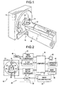
- a computed tomograph (CT) imaging system 10 is shown as including a gantry 12 representative of a "third generation" CT scanner.
- Gantry 12 has an x-ray source 14 that projects a beam of x-rays 16 toward a detector array 18 on the opposite side of gantry 12.
- Detector array 18 is formed by detector elements 20 that together sense the projected x-rays that pass through an object 22, for example a medical patient.
- Each detector element 20 produces an electrical signal that represents the intensity of an impinging x-ray beam and hence the attenuation of the beam as it passes through patient 22.
- gantry 12 and the components mounted thereon rotate about a center of rotation or isocenter 24.
- Control mechanism 26 includes an x-ray controller 28 that provides power and timing signals to x-ray source 14 and a gantry motor controller 30 that controls the rotational speed and position of gantry 12.
- a data acquisition system (DAS) 32 in control mechanism 26 samples analog data from detector elements 20 and converts the data to digital signals for subsequent processing.
- An image reconstructor 34 receives sampled and digitized x-ray data from DAS 32 and performs high-speed image reconstruction. The reconstructed image is applied as an input to a computer 36 that stores the image in a mass storage device 38.
- DAS data acquisition system
- Computer 36 also receives commands and scanning parameters from an operator via console 40 that has a keyboard.
- An associated cathode ray tube display 42 allows the operator to observe the reconstructed image and other data from computer 36.
- the operator supplied commands and parameters are used by computer 36 to provide control signals and information to DAS 32, x-ray controller 28 and gantry motor controller 30.
- computer 36 operates a table motor controller 44 that controls a motorized table 46 to position patient 22 in gantry 12. Particularly, table 46 moves portions of patient 22 through gantry opening 48.
- x-ray beam 16 emanates from a focal spot 50 of x-ray source 14 ( Figure 2).
- X-ray beam 16 is collimated by collimator 52, and collimated beam 16 is projected toward detector array 18.
- Detector array 18 is fabricated in a multi-slice configuration and includes detector element rows 54, 56, 58 and 60 for projection data collection.
- a plane 86 generally referred to as the "fan beam plane", contains the centerline of focal spot 50 and the centerline of beam 16. Fan beam plane 86 is illustrated in Figure 3 as being aligned with a centerline D 0 of detector array 18, although fan beam plane 86 will not always be so aligned.
- Detector element rows 62, 64, 66 and 68 serve as z -position detectors for determining a z -axis position of x-ray beam 16.
- detector rows 62, 64, 66, and 68 are rows of detector array 18.
- Outer rows 62 and 68 are selected to be at least substantially within penumbra 70 of beam 16.
- Inner rows 64 and 66 are selected to be at least substantially within umbra 72 of beam 16.
- "At least substantially within” means either entirely within or at least sufficiently within so that outer row 62 and 68 signal intensities depend on an x-ray beam position and inner row 64 and 66 signal intensities provide references against which outer row signals are compared.
- collimator 52 includes tapered cams 74 and 76.
- X-ray controller 28 controls positioning of cams 74 and 76. Each cam can be independently positioned to alter position and width of x-ray umbra 72 relative to an edge (not shown) of detector array 18.
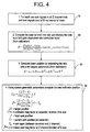
- one embodiment of a closed-loop method for positioning beam 16 comprises comparing signals representative of x-ray intensity received from different rows of detector elements and positioning an x-ray beam in accordance with results of the comparison.
- signals representative of x-ray intensity from detector rows 62, 64, 66 and 68 are summed 78 to obtain row sums. The summation is over views taken in a 20-millisecond interval.
- hardware circuitry (not shown) in DAS 32 performs offset correction and determines row sums from signals received from outer row 62 and from inner row 64.
- a corrected ratio R is determined 80 by determining a ratio of a sum of signals received from outer row 62 to a sum of signals received from inner row 64 and multiplying the ratio by a ratio correction factor.
- the ratio correction factor determined from imaging system 10 calibration, accounts for different relative DAS gains between outer row 62 and inner row 64.
- Beam position Z (R) then is determined 82, in millimeters relative to a centerline. Beam position Z is obtained by applying a predetermined beam position transfer function to the corrected ratio to calculate the x-ray beam position.
- Beam position transfer function Z ( R ) and its limits are specified at imaging system 10 calibration.
- a new collimator position is then determined 84.
- a new position for collimator 52 then is determined 84 for a detector element 20 positioned toward isocenter 24.
- Collimator 52 is repositioned where an edge (not shown) of collimator 52 would meet a line between focal spot position f and a target beam position Z t which has been specified at imaging system 10 calibration.
- steps 78, 80, 82, and 84 are performed independently for each side of collimator 52 at intervals to continuously obtain new positions for each side of collimator 52.
- These intervals are, in one embodiment, 20 milliseconds, to sample the x-ray beam 16 position 25 times during a 0.5 second scan to minimize control loop lag error.
- the interval is between 5 milliseconds and 50 milliseconds.
- the interval is between a minimum value sufficient to avoid effects of quantum noise and high frequency variation (such as due to x-ray tube anode movement at a run frequency between 50 Hz and 160 Hz) and a maximum contrained by a slew rate of the sag curve. Sampling the changing sag curve frequently avoids excessive positioning error. (Sag is a periodic movement of x-ray beam 16 resulting from gravity and from centrifugal forces acting on mechanical structure during a rotation of gantry 12.)
- z -position detectors 62, 64, 66 or 68 may become blocked by patient clothing, blankets, or other object.
- the loop sample interval is adjusted downward. In one embodiment, the loop sample interval is adjusted downward to 5 milliseconds. After 4 milliseconds of stabilization, the position of the beam is measured and collimator positioning is started to further minimize initial position errors.
- a signal from a last data detector element 90 adjacent a z -position detector 62, 64, 66 or 68 is compared to an expected signal Sx .
- Z -position detector blockage is assumed, in one embodiment, if a last data detector element 20 signal is less than 0.9 times expected signal Sx . In other embodiments, detector blockage is assumed when a last data detector element 20 signal is less than a value between 0.95 and 0.5 times expected signal Sx .
- Gain factor g allows expected signal Sx to be adjusted according to a gain value used for scanning. In one embodiment, this gain value is selectable from a plurality of gain values available in system 10.
- closed loop tracking is suspended when signal corruption is detected.
- Signal corruption is detected, for example, by determining an actual focal spot length from a beam position and a collimator position, and comparing the actual focal spot length to a nominal focal spot length.
- a difference threshold for assuming corruption is as small as 0.05 millimeter or as large as about 0.6 millimeter.
- a value is selected between a lower limit set by higher probabilities of false activation due to noise, x-ray scatter and/or momentary beam position disturbances and an upper limit that still provides some of the advantages of tracking.
- beam position measurement continues at a decreased interval, as when a blockage is detected.
- Such corruption may occur, for example, for a short time just prior to or just following detection of a patient blockage. If the corruption persists, for example, over 90° of rotation of gantry 12 without detecting a patient blockage, a malfunction of the tracking system requiring servicing has likely occurred. In such an event, a scan is immediately aborted to avoid patient dose and collection of non-diagnostic quality images.
- a limit is set from as little as 45° to as much as 360° of a rotation of gantry 12. In other embodiments, a limit is set between a value at which a false alarm rate due to scatter and/or an occasional exceptionally long partial patient 22 blockage is acceptable and an upper limit representing a design choice as to how long compromised operation (high dose and/or non-diagnostic quality images) can be tolerated before terminating a scan.
- position of focal spot 50 changes as source 14 cools over time.
- an initial focal spot position is approximated from information obtained when a focal spot position was last measured.
- An approximation of a linear function is used to model focal spot position change during cooling in one embodiment, and in another embodiment, the linear function is a 97 nanometer per second linear function. Because position change with cooling is an exponential function, the linear approximation is clamped at 0.15 millimeters. This clamping corresponds to approximately 20% of a cooling change in system 10 when fully cold, where a linear approximation to the exponential function suffices.
- a fully cold position requires 8 to 12 hours without patient scanning, and a tube warm up prior to patient scanning is normally requested if the tube has been off more than 1 hour. Therefore, a fully cold position, although possible, is not likely during normal patient scanning.
- a current measured position of the focal spot is established again for initial positioning of the collimator.
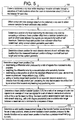
- FIG. 5 illustrates one embodiment of a method for calibrating tracking loop parameters.
- data from a stationary sweep scan is collected 100 while collimator 52 is stepped through a sequence of z -axis positions.
- Beam 16 is incremented 0.3 millimeters on detector array 18 exposure surface for each collimator 52 step position.
- the sweep scan data is offset-corrected and view averaged 102 to obtain a set of detector samples for each collimator 52 step position.
- a position of the focal spot is then determined 104.
- a collimator 52 z -axis position offset from detector array centerline D 0 is determined 104, as the point where outer rows 62 and 68 receive signals of half-maximum intensity at full detector element 20 width.
- Position of focal spot 50 during sweep scan then is determined 104 from collimator 52 z -axis offset and nominal system 10 geometric parameters.
- a beam 16 position is determined 106 for each detector element 20 at each collimator 52 step position. Beam 16 positions are determined from sweep scan focal spot 50 position, nominal length of focal spot 50, and nominal system 10 geometry.
- Target beam position Z t then is determined 108 for detector element 20 positioned toward isocenter 24.
- beam 16 is directed at target beam position Z t , beam 16 is sufficiently close to detector array 18 edge 92 to prevent imaging artifacts but is far enough away to minimize patient dosage.
- ratios of detector samples for successive collimator 52 step positions are utilized to determine a detector differential error.
- a reconstruction error sensitivity function w ( i ) then is applied to weight the detector differential error.
- Reconstruction error sensitivity function w ( i ) is related to the percent positive contribution of a detector element 20 as a function of its radial distance from isocenter 24.
- Function w ( i ) in one embodiment, is computed from nominal system geometry.
- w ( i ) is empirically determined.
- i represents detector element position from isocenter 24
- b ( i ) represents an artifact threshold, i.e. a percent differential error, for a double detector element 20 error.
- a collimator 52 step position SP is determined for which the weighted detector differential error exceeds a limit L empirically known to produce image artifacts, for example, 0.04 percent.
- Target beam position Z t then is set for the isocenter detector element at a distance just preceding SP by an amount exceeding applicable tracking loop positioning error.
- Beam position transfer function Z ( R ) then is determined 110 for a ratio R of an average of outer row 62 to inner row 64 signals for a set of detector elements at an extreme end of x-ray fan beam 16.
- a valid position measurement range for Z ( R ) is determined 112 as between end limits of the set of collimator 52 step positions for which an error between a beam 16 position determined by Z and an actual beam 16 position is less than a predetermined limit, for example, 0.2 millimeters.
- the predetermined limit is between 0.1 millimeters to 0.6 millimeters.
- the predetermined limit is set at a value between a lower limit just above a value at which a range of beam 16 position that can be precisely measured is too limited, and just below a lower limit that is deemed to create tracking errors so large as to unacceptably compromise the benefits of tracking.
- the above described tracking loop senses the signal ratio between detector rows and moves system collimation to maintain the x-ray beam very close to the imaging system detector array edge during patient scanning. As a result, patient x-ray dosage is reduced 20 to 40 percent without sacrificing image quality.
- various combinations of z -detector row signals can be used as the inner and outer row signals, thereby becoming identified as such, or a different and/or more elaborate transfer function can be used to determine a beam position.
Landscapes
- Health & Medical Sciences (AREA)
- Life Sciences & Earth Sciences (AREA)
- Engineering & Computer Science (AREA)
- Medical Informatics (AREA)
- Optics & Photonics (AREA)
- Biomedical Technology (AREA)
- Biophysics (AREA)
- High Energy & Nuclear Physics (AREA)
- Veterinary Medicine (AREA)
- Nuclear Medicine, Radiotherapy & Molecular Imaging (AREA)
- Public Health (AREA)
- Pathology (AREA)
- Radiology & Medical Imaging (AREA)
- Physics & Mathematics (AREA)
- Heart & Thoracic Surgery (AREA)
- Molecular Biology (AREA)
- Surgery (AREA)
- Animal Behavior & Ethology (AREA)
- General Health & Medical Sciences (AREA)
- Pulmonology (AREA)
- Theoretical Computer Science (AREA)
- Apparatus For Radiation Diagnosis (AREA)
Applications Claiming Priority (2)
| Application Number | Priority Date | Filing Date | Title |
|---|---|---|---|
| US384169 | 1999-08-27 | ||
| US09/384,169 US6385279B1 (en) | 1999-08-27 | 1999-08-27 | Methods and apparatus for positioning a CT imaging x-ray beam |
Publications (2)
| Publication Number | Publication Date |
|---|---|
| EP1078599A1 true EP1078599A1 (de) | 2001-02-28 |
| EP1078599B1 EP1078599B1 (de) | 2009-03-25 |
Family
ID=23516309
Family Applications (1)
| Application Number | Title | Priority Date | Filing Date |
|---|---|---|---|
| EP00307143A Expired - Lifetime EP1078599B1 (de) | 1999-08-27 | 2000-08-21 | Verfahren und Vorrichtung zur Ausrichtung des Röntgenstrahls eines bildgebenden Computertomographens |
Country Status (5)
| Country | Link |
|---|---|
| US (2) | US6385279B1 (de) |
| EP (1) | EP1078599B1 (de) |
| JP (1) | JP4554045B2 (de) |
| DE (1) | DE60041850D1 (de) |
| IL (1) | IL137863A (de) |
Cited By (4)
| Publication number | Priority date | Publication date | Assignee | Title |
|---|---|---|---|---|
| WO2008132635A2 (en) * | 2007-04-25 | 2008-11-06 | Koninklijke Philips Electronics, N.V. | X-ray beam z-axis positioning |
| CN101900823B (zh) * | 2009-05-31 | 2012-10-03 | 上海西门子医疗器械有限公司 | 一种x射线偏移的校正方法和装置 |
| WO2012152809A3 (de) * | 2011-05-09 | 2013-01-31 | Fraunhofer-Gesellschaft zur Förderung der angewandten Forschung e.V. | Durchstrahlungssystem und kalibrierung desselben |
| CN104574460A (zh) * | 2014-12-31 | 2015-04-29 | 沈阳东软医疗系统有限公司 | 一种ct图像重建方法和装置 |
Families Citing this family (23)
| Publication number | Priority date | Publication date | Assignee | Title |
|---|---|---|---|---|
| US6680995B2 (en) | 2001-10-31 | 2004-01-20 | Ge Medical Systems Global Technology Co., Llc | Method and apparatus of determining and displaying a helical artifact index |
| US6597756B1 (en) | 2002-06-19 | 2003-07-22 | Ge Medical Systems Global Technology Company, Llc | Methods and apparatus for multi-slice image reconstruction |
| EP1551302B1 (de) * | 2002-07-25 | 2012-02-08 | Gendex Corporation | Digitales echtzeit-röntgengerät und verfahren |
| US6873676B2 (en) * | 2003-03-05 | 2005-03-29 | Ge Medical Systems Global Technology Company, Llc | Convolution reconstruction algorithm for multi-slice CT |
| US6866419B2 (en) * | 2003-03-12 | 2005-03-15 | Ge Medical Systems Global Technology Company Llc | Methods and apparatus for motion correction in imaging systems |
| US7366280B2 (en) * | 2003-06-19 | 2008-04-29 | General Electric Company | Integrated arc anode x-ray source for a computed tomography system |
| JP4062232B2 (ja) * | 2003-10-20 | 2008-03-19 | 株式会社日立製作所 | X線ct装置及びx線ct装置による撮像方法 |
| US6980623B2 (en) * | 2003-10-29 | 2005-12-27 | Ge Medical Systems Global Technology Company Llc | Method and apparatus for z-axis tracking and collimation |
| US7020243B2 (en) * | 2003-12-05 | 2006-03-28 | Ge Medical Systems Global Technology Company Llc | Method and system for target angle heel effect compensation |
| US7187748B2 (en) * | 2003-12-30 | 2007-03-06 | Ge Medical Systems Global Technology Company, Llc | Multidetector CT imaging method and apparatus with reducing radiation scattering |
| US7113570B2 (en) * | 2005-02-08 | 2006-09-26 | General Electric Company | Methods and systems for helical overscan reduction |
| US7101078B1 (en) * | 2005-02-11 | 2006-09-05 | General Electric Company | Methods and systems for imaging system radiation source alignment |
| DE102005018811B4 (de) * | 2005-04-22 | 2008-02-21 | Siemens Ag | Blendenvorrichtung für eine zur Abtastung eines Objektes vorgesehene Röntgeneinrichtung und Verfahren für eine Blendenvorrichtung |
| DE102005020124B4 (de) * | 2005-04-29 | 2011-07-14 | Siemens AG, 80333 | Röntgensystem, enthaltend einen zugeordneten, mobilen Festkörperdetektor und Verfahren zur Aufnahme und Anzeige eines Röntgenbildes |
| US7257187B2 (en) * | 2005-05-06 | 2007-08-14 | General Electric Company | Methods and apparatus for calibrating CT x-ray beam tracking loop |
| US8571176B2 (en) | 2011-06-17 | 2013-10-29 | General Electric Company | Methods and apparatus for collimation of detectors |
| US8699659B2 (en) | 2011-06-23 | 2014-04-15 | General Electric Company | Systems and methods for focal spot motion correction |
| US8976934B2 (en) * | 2012-06-19 | 2015-03-10 | General Electric Company | Radiation apertures for X-ray collimators |
| US20180241452A1 (en) * | 2017-02-23 | 2018-08-23 | Qualcomm Incorporated | Beam sweeping for control and data transmissions |
| EP3413691A1 (de) * | 2017-06-08 | 2018-12-12 | Koninklijke Philips N.V. | Vorrichtung zur erzeugung von röntgenstrahlen |
| US10779791B2 (en) * | 2018-03-16 | 2020-09-22 | General Electric Company | System and method for mobile X-ray imaging |
| CN109431534B (zh) * | 2018-11-30 | 2022-12-06 | 深圳安科高技术股份有限公司 | 一种射线准直器的自校准方法及其系统 |
| US10898159B2 (en) * | 2019-01-11 | 2021-01-26 | General Electric Company | X-ray imaging system use and calibration |
Citations (3)
| Publication number | Priority date | Publication date | Assignee | Title |
|---|---|---|---|---|
| WO1996016530A1 (en) * | 1994-11-22 | 1996-05-30 | Analogic Corporation | X-ray focal spot movement compensation system |
| DE19650528A1 (de) * | 1995-12-21 | 1997-06-26 | Gen Electric | Verfahren und Vorrichtungen zur Bestimmung einer Röntgenstrahl-Position in Mehrfach-Schnitt-Computer-Tomographie-Abtasteinrichtungen |
| JPH119584A (ja) * | 1997-06-25 | 1999-01-19 | Ge Yokogawa Medical Syst Ltd | X線ビームトラッキング方法、x線ビーム位置測定方法およびx線ct装置 |
Family Cites Families (15)
| Publication number | Priority date | Publication date | Assignee | Title |
|---|---|---|---|---|
| JPS5894833A (ja) * | 1981-12-01 | 1983-06-06 | 株式会社東芝 | X線ct装置 |
| US5485493A (en) | 1988-10-20 | 1996-01-16 | Picker International, Inc. | Multiple detector ring spiral scanner with relatively adjustable helical paths |
| US4991189A (en) | 1990-04-16 | 1991-02-05 | General Electric Company | Collimation apparatus for x-ray beam correction |
| DE4207006C2 (de) | 1992-03-05 | 1994-07-14 | Siemens Ag | Computertomograph |
| US5347216A (en) * | 1992-06-23 | 1994-09-13 | General Electric Company | Fast NMR image acquisition with spectrally selective inversion pulse |
| US5469429A (en) | 1993-05-21 | 1995-11-21 | Kabushiki Kaisha Toshiba | X-ray CT apparatus having focal spot position detection means for the X-ray tube and focal spot position adjusting means |
| JP2774790B2 (ja) * | 1995-02-16 | 1998-07-09 | 株式会社東芝 | X線ctスキャナ |
| WO1997019637A1 (en) | 1995-11-28 | 1997-06-05 | Analogic Corporation | Precalibrating x-ray tube focal spot |
| US5579359A (en) * | 1995-12-21 | 1996-11-26 | General Electric Company | Methods and apparatus for calibrating detector cell output signals |
| US5706326A (en) * | 1995-12-22 | 1998-01-06 | General Electric Company | Systems and methods of determining focal spot x-axis position from projection data |
| JP3742690B2 (ja) * | 1996-08-30 | 2006-02-08 | 株式会社東芝 | X線ctスキャナ |
| US5761257A (en) | 1996-12-02 | 1998-06-02 | General Electric Company | Normalizing projection data in a computed tomography system |
| JPH1133019A (ja) * | 1997-07-18 | 1999-02-09 | Ge Yokogawa Medical Syst Ltd | 放射線照射・検出装置および放射線断層撮影装置 |
| JPH1189825A (ja) * | 1997-09-25 | 1999-04-06 | Ge Yokogawa Medical Systems Ltd | 放射線照射・検出装置および放射線断層撮影装置 |
| US6056437A (en) * | 1998-08-25 | 2000-05-02 | General Electric Company | Methods and apparatus for imaging system detector alignment |
-
1999
- 1999-08-27 US US09/384,169 patent/US6385279B1/en not_active Expired - Lifetime
-
2000
- 2000-08-15 IL IL13786300A patent/IL137863A/en not_active IP Right Cessation
- 2000-08-21 EP EP00307143A patent/EP1078599B1/de not_active Expired - Lifetime
- 2000-08-21 DE DE60041850T patent/DE60041850D1/de not_active Expired - Lifetime
- 2000-08-24 JP JP2000253221A patent/JP4554045B2/ja not_active Expired - Fee Related
- 2000-12-21 US US09/746,456 patent/US6359958B2/en not_active Expired - Lifetime
Patent Citations (3)
| Publication number | Priority date | Publication date | Assignee | Title |
|---|---|---|---|---|
| WO1996016530A1 (en) * | 1994-11-22 | 1996-05-30 | Analogic Corporation | X-ray focal spot movement compensation system |
| DE19650528A1 (de) * | 1995-12-21 | 1997-06-26 | Gen Electric | Verfahren und Vorrichtungen zur Bestimmung einer Röntgenstrahl-Position in Mehrfach-Schnitt-Computer-Tomographie-Abtasteinrichtungen |
| JPH119584A (ja) * | 1997-06-25 | 1999-01-19 | Ge Yokogawa Medical Syst Ltd | X線ビームトラッキング方法、x線ビーム位置測定方法およびx線ct装置 |
Non-Patent Citations (1)
| Title |
|---|
| PATENT ABSTRACTS OF JAPAN vol. 1999, no. 04 30 April 1999 (1999-04-30) * |
Cited By (9)
| Publication number | Priority date | Publication date | Assignee | Title |
|---|---|---|---|---|
| WO2008132635A2 (en) * | 2007-04-25 | 2008-11-06 | Koninklijke Philips Electronics, N.V. | X-ray beam z-axis positioning |
| WO2008132635A3 (en) * | 2007-04-25 | 2008-12-24 | Koninkl Philips Electronics Nv | X-ray beam z-axis positioning |
| US8331529B2 (en) | 2007-04-25 | 2012-12-11 | Koninklijke Philips Electronics N.V. | X-ray beam z-axis positioning |
| CN101900823B (zh) * | 2009-05-31 | 2012-10-03 | 上海西门子医疗器械有限公司 | 一种x射线偏移的校正方法和装置 |
| WO2012152809A3 (de) * | 2011-05-09 | 2013-01-31 | Fraunhofer-Gesellschaft zur Förderung der angewandten Forschung e.V. | Durchstrahlungssystem und kalibrierung desselben |
| EP2977009A3 (de) * | 2011-05-09 | 2016-05-18 | Fraunhofer-Gesellschaft zur Förderung der angewandten Forschung e.V. | Durchstrahlungssystem und kalibrierung desselben |
| US9429665B2 (en) | 2011-05-09 | 2016-08-30 | Fraunhofer-Gesellschaft Zur Foerderung Der Angewandten Forschung E.V. | Radiation penetration system and calibration of the same |
| CN104574460A (zh) * | 2014-12-31 | 2015-04-29 | 沈阳东软医疗系统有限公司 | 一种ct图像重建方法和装置 |
| CN104574460B (zh) * | 2014-12-31 | 2017-06-27 | 沈阳东软医疗系统有限公司 | 一种ct图像重建方法和装置 |
Also Published As
| Publication number | Publication date |
|---|---|
| US6359958B2 (en) | 2002-03-19 |
| US6385279B1 (en) | 2002-05-07 |
| IL137863A (en) | 2005-12-18 |
| DE60041850D1 (de) | 2009-05-07 |
| US20010031033A1 (en) | 2001-10-18 |
| IL137863A0 (en) | 2001-10-31 |
| JP2001095792A (ja) | 2001-04-10 |
| EP1078599B1 (de) | 2009-03-25 |
| JP4554045B2 (ja) | 2010-09-29 |
Similar Documents
| Publication | Publication Date | Title |
|---|---|---|
| US6385279B1 (en) | Methods and apparatus for positioning a CT imaging x-ray beam | |
| US6411677B1 (en) | Methods and apparatus for calibrating CT x-ray beam tracking loop | |
| US6370218B1 (en) | Methods and systems for determining x-ray beam position in multi-slice computed tomography scanners | |
| JP4880587B2 (ja) | コンピュータ断層撮影のための動的線量制御 | |
| EP1114617B1 (de) | Verfahren und Gerät zur automatischen Patientenpositionierung | |
| US5400378A (en) | Dynamic dose control in multi-slice CT scan | |
| US7409043B2 (en) | Method and apparatus to control radiation tube focal spot size | |
| EP1047338B1 (de) | Verfahren und gerät zur korrektion der röntgenstrahlbewegung | |
| US5473656A (en) | Computed tomography system with correction for z-axis detector non-uniformity | |
| JP4159188B2 (ja) | 管電流調節方法および装置並びにx線ct装置 | |
| US20060251210A1 (en) | Methods and apparatus for calibrating CT X-ray beam tracking loop | |
| US5579359A (en) | Methods and apparatus for calibrating detector cell output signals | |
| US6327331B1 (en) | Method and apparatus for analyzing CT z-axis beam positioning | |
| EP0973047A2 (de) | Verfahren und Vorrichtung zur Verminderung der Z-Achse Umgleichförmigkeiten Artefakten | |
| EP1085469A2 (de) | Verfahren und Vorrichtung zur Vorfilterung in Bildkonstruktion | |
| EP1103221B1 (de) | Verfahren und Gerät zur Optimisierung der Bildqualität vom Komputertomographen mit optimaler Datenerfassung | |
| EP1077045B1 (de) | Verfahren und Gerät für Projektionsdatenkorrektur und für strahlungstomographische Bilderzeugung | |
| US5610963A (en) | Methods and systems for determining the z-axis profile of a detector in a CT system | |
| WO2002043451A2 (en) | Methods and apparatus for tube-spit correction | |
| IL138652A (en) | System for dynamic adjustment of a component in the imaging system of computerized tomography |
Legal Events
| Date | Code | Title | Description |
|---|---|---|---|
| PUAI | Public reference made under article 153(3) epc to a published international application that has entered the european phase |
Free format text: ORIGINAL CODE: 0009012 |
|
| AK | Designated contracting states |
Kind code of ref document: A1 Designated state(s): DE NL |
|
| AX | Request for extension of the european patent |
Free format text: AL;LT;LV;MK;RO;SI |
|
| 17P | Request for examination filed |
Effective date: 20010828 |
|
| AKX | Designation fees paid |
Free format text: DE NL |
|
| 17Q | First examination report despatched |
Effective date: 20031216 |
|
| APBN | Date of receipt of notice of appeal recorded |
Free format text: ORIGINAL CODE: EPIDOSNNOA2E |
|
| APBR | Date of receipt of statement of grounds of appeal recorded |
Free format text: ORIGINAL CODE: EPIDOSNNOA3E |
|
| APBV | Interlocutory revision of appeal recorded |
Free format text: ORIGINAL CODE: EPIDOSNIRAPE |
|
| 17Q | First examination report despatched |
Effective date: 20031216 |
|
| GRAP | Despatch of communication of intention to grant a patent |
Free format text: ORIGINAL CODE: EPIDOSNIGR1 |
|
| GRAS | Grant fee paid |
Free format text: ORIGINAL CODE: EPIDOSNIGR3 |
|
| GRAA | (expected) grant |
Free format text: ORIGINAL CODE: 0009210 |
|
| AK | Designated contracting states |
Kind code of ref document: B1 Designated state(s): DE NL |
|
| REF | Corresponds to: |
Ref document number: 60041850 Country of ref document: DE Date of ref document: 20090507 Kind code of ref document: P |
|
| PLBE | No opposition filed within time limit |
Free format text: ORIGINAL CODE: 0009261 |
|
| STAA | Information on the status of an ep patent application or granted ep patent |
Free format text: STATUS: NO OPPOSITION FILED WITHIN TIME LIMIT |
|
| 26N | No opposition filed |
Effective date: 20091229 |
|
| PGFP | Annual fee paid to national office [announced via postgrant information from national office to epo] |
Ref country code: NL Payment date: 20190726 Year of fee payment: 20 |
|
| PGFP | Annual fee paid to national office [announced via postgrant information from national office to epo] |
Ref country code: DE Payment date: 20190722 Year of fee payment: 20 |
|
| REG | Reference to a national code |
Ref country code: DE Ref legal event code: R071 Ref document number: 60041850 Country of ref document: DE |
|
| REG | Reference to a national code |
Ref country code: NL Ref legal event code: MK Effective date: 20200820 |