EP1077449A1 - Information readout apparatus and information readout method - Google Patents
Information readout apparatus and information readout method Download PDFInfo
- Publication number
- EP1077449A1 EP1077449A1 EP00117817A EP00117817A EP1077449A1 EP 1077449 A1 EP1077449 A1 EP 1077449A1 EP 00117817 A EP00117817 A EP 00117817A EP 00117817 A EP00117817 A EP 00117817A EP 1077449 A1 EP1077449 A1 EP 1077449A1
- Authority
- EP
- European Patent Office
- Prior art keywords
- resolution
- readout
- reference value
- detecting
- recording medium
- Prior art date
- Legal status (The legal status is an assumption and is not a legal conclusion. Google has not performed a legal analysis and makes no representation as to the accuracy of the status listed.)
- Withdrawn
Links
Images


Classifications
-
- G—PHYSICS
- G11—INFORMATION STORAGE
- G11B—INFORMATION STORAGE BASED ON RELATIVE MOVEMENT BETWEEN RECORD CARRIER AND TRANSDUCER
- G11B7/00—Recording or reproducing by optical means, e.g. recording using a thermal beam of optical radiation by modifying optical properties or the physical structure, reproducing using an optical beam at lower power by sensing optical properties; Record carriers therefor
- G11B7/12—Heads, e.g. forming of the optical beam spot or modulation of the optical beam
- G11B7/125—Optical beam sources therefor, e.g. laser control circuitry specially adapted for optical storage devices; Modulators, e.g. means for controlling the size or intensity of optical spots or optical traces
- G11B7/126—Circuits, methods or arrangements for laser control or stabilisation
-
- G—PHYSICS
- G11—INFORMATION STORAGE
- G11B—INFORMATION STORAGE BASED ON RELATIVE MOVEMENT BETWEEN RECORD CARRIER AND TRANSDUCER
- G11B11/00—Recording on or reproducing from the same record carrier wherein for these two operations the methods are covered by different main groups of groups G11B3/00 - G11B7/00 or by different subgroups of group G11B9/00; Record carriers therefor
- G11B11/10—Recording on or reproducing from the same record carrier wherein for these two operations the methods are covered by different main groups of groups G11B3/00 - G11B7/00 or by different subgroups of group G11B9/00; Record carriers therefor using recording by magnetic means or other means for magnetisation or demagnetisation of a record carrier, e.g. light induced spin magnetisation; Demagnetisation by thermal or stress means in the presence or not of an orienting magnetic field
- G11B11/105—Recording on or reproducing from the same record carrier wherein for these two operations the methods are covered by different main groups of groups G11B3/00 - G11B7/00 or by different subgroups of group G11B9/00; Record carriers therefor using recording by magnetic means or other means for magnetisation or demagnetisation of a record carrier, e.g. light induced spin magnetisation; Demagnetisation by thermal or stress means in the presence or not of an orienting magnetic field using a beam of light or a magnetic field for recording by change of magnetisation and a beam of light for reproducing, i.e. magneto-optical, e.g. light-induced thermomagnetic recording, spin magnetisation recording, Kerr or Faraday effect reproducing
- G11B11/10595—Control of operating function
-
- G—PHYSICS
- G11—INFORMATION STORAGE
- G11B—INFORMATION STORAGE BASED ON RELATIVE MOVEMENT BETWEEN RECORD CARRIER AND TRANSDUCER
- G11B11/00—Recording on or reproducing from the same record carrier wherein for these two operations the methods are covered by different main groups of groups G11B3/00 - G11B7/00 or by different subgroups of group G11B9/00; Record carriers therefor
- G11B11/10—Recording on or reproducing from the same record carrier wherein for these two operations the methods are covered by different main groups of groups G11B3/00 - G11B7/00 or by different subgroups of group G11B9/00; Record carriers therefor using recording by magnetic means or other means for magnetisation or demagnetisation of a record carrier, e.g. light induced spin magnetisation; Demagnetisation by thermal or stress means in the presence or not of an orienting magnetic field
- G11B11/105—Recording on or reproducing from the same record carrier wherein for these two operations the methods are covered by different main groups of groups G11B3/00 - G11B7/00 or by different subgroups of group G11B9/00; Record carriers therefor using recording by magnetic means or other means for magnetisation or demagnetisation of a record carrier, e.g. light induced spin magnetisation; Demagnetisation by thermal or stress means in the presence or not of an orienting magnetic field using a beam of light or a magnetic field for recording by change of magnetisation and a beam of light for reproducing, i.e. magneto-optical, e.g. light-induced thermomagnetic recording, spin magnetisation recording, Kerr or Faraday effect reproducing
- G11B11/10502—Recording on or reproducing from the same record carrier wherein for these two operations the methods are covered by different main groups of groups G11B3/00 - G11B7/00 or by different subgroups of group G11B9/00; Record carriers therefor using recording by magnetic means or other means for magnetisation or demagnetisation of a record carrier, e.g. light induced spin magnetisation; Demagnetisation by thermal or stress means in the presence or not of an orienting magnetic field using a beam of light or a magnetic field for recording by change of magnetisation and a beam of light for reproducing, i.e. magneto-optical, e.g. light-induced thermomagnetic recording, spin magnetisation recording, Kerr or Faraday effect reproducing characterised by the transducing operation to be executed
- G11B11/10515—Reproducing
-
- G—PHYSICS
- G11—INFORMATION STORAGE
- G11B—INFORMATION STORAGE BASED ON RELATIVE MOVEMENT BETWEEN RECORD CARRIER AND TRANSDUCER
- G11B7/00—Recording or reproducing by optical means, e.g. recording using a thermal beam of optical radiation by modifying optical properties or the physical structure, reproducing using an optical beam at lower power by sensing optical properties; Record carriers therefor
- G11B7/004—Recording, reproducing or erasing methods; Read, write or erase circuits therefor
- G11B7/005—Reproducing
Definitions
- This invention relates to an information readout apparatus and an information readout method for reading out information from a recording medium such as an optical disk in a controlled manner. More particularly, the present invention relates to an information readout apparatus and an information readout method adapted to optimally control the detection window of a super resolution optical disk that is operating as readout area within the light beam irradiation range of the disk.
- optical disks are popularly used as medium for storing image information, sound information and computer data because of the advantage of having a large storage capacity.
- Known super resolution disks include MSR (magnetic super resolution) disks, PSR (phase change super resolution) disks and RSR (ROM super resolution) disks.
- known readout systems include the RAD (rear aperture detection) system, the FAD (front aperture detection) system and the double mask system which are discriminated from each other in terms of the position of the readout area to be detected by means of a light spot formed by a beam spot.
- the CAD (central aperture detection) system is also known as a variation of the RAD system.
- an MSR disk of the RAD system represents the technology of forming a recording layer by using a multilayer film comprising a readout layer and a recording/holding layer that are magnetically coupled with each other and heating the readout layer to a predetermined temperature range by irradiating it with a laser beam for the purpose of readout so that only the magnetized signals stored in the heated area of the recording/holding layer can be transferred to the readout layer and actually read out.
- a recorded mark smaller than the diameter of the light spot formed by the laser beam can be transferred and read out by means of this technology.
- the area from which the magnetized signals are transferred to the readout layer and can be read out is referred to as detection window or aperture.
- an MSR disk of the CAD system is so adapted that an opto-magnetic recording medium comprising a recording layer and an intra-planarly magnetizable readout layer is irradiated with a light beam from the side of the readout layer to raise the temperature of the readout layer above a predetermined level only in the area irradiated with the light beam. Then, the state of magnetization of the readout layer is shifted from that of intra-planarly magnetization of only the detection window (aperture) in the area that is irradiated with the light beam to raise the temperature thereof above the predetermined level to that of vertical magnetization of transferring the magnetism of the detection window to the corresponding area of the recording layer. As a result, a recorded mark smaller than the diameter of the light spot formed by the light beam can be read out.
- the readout condition for optimizing the signal quality varies as a function of the sensitivity of the medium, the ambient temperature and perturbation such as skew of the medium substrate.
- the size of the aperture varies as a function of the readout power of the light beam. Therefore, as the readout power is raised, the size of the aperture increases to consequently increases the area to be used for reading out the recorded mark on the recording layer arranged under the readout layer.
- the C/N ratio the carrier to noise ratio
- the super resolution effect is reduced so that any of the recorded marks of the adjacent tracks may be read out and hence unrelated signals may become detected to raise the cross talk level.
- the C/N ratio lowers as the readout power is reduced.
- the inter-code interference factor and the cross talk factor increases when the readout power is too strong, whereas the C/R ratio falls when the readout power is too weak.
- the jitter that appears as positional error of changeover from 1 to 0 or vice versa becomes remarkable when reading out the signal.
- Japanese Patent Application Laid-Open No. 8-63817 proposes a technique of optimizing the effect of signal readout by detecting the amplitude of each of the read out signals representing so many patterns of recorded marks having different lengths, comparing the signal levels and controlling the readout power to bring them close to a reference value.
- the size of the detection window can be controlled by reducing the readout power when the ambient temperature is high.
- the signals representing the respective patterns of recorded marks for detecting the resolution are arranged on the data area of the optical disk to consequently give rise to a problem of an enhanced level of redundancy, which by turn reduces the available recording capacity of the optical disk.
- a specific area (lead-in area) is provided on the optical disk to store the signals representing the respective patterns of recorded marks, a track jumping action is needed to get to that specific area in order to control the readout power during a signal readout operation at the cost of the access efficiency of the optical disk.
- the signals representing the recorded patterns are distributed over the entire surface of the optical disk to avoid this problem, they are more affected by the surface defects, if any, of the optical disk.
- the object of the present invention to provide an information readout apparatus and an information readout method adapted to efficiently correct any change in the aperture size without sacrificing the recording capacity and without using a clock dedicated to detect the amplitude of the read out signals having respective specific mark lengths.
- an information readout apparatus for irradiating a recording medium having a recording layer and a readout layer with a light beam and reading the recorded information on the recording layer by opening a detecting window smaller than the area irradiated with the optical beam, said apparatus comprising:
- an information readout method for irradiating a recording medium having a recording layer and a readout layer with a light beam and reading the recorded information on the recording layer by opening a detecting window smaller than the area irradiated with the optical beam, said method comprising steps of:
- the resolution may be detected on the basis of the quotient obtained by dividing the difference X between the sample value Y near the peak of said isolated mark and the sample value adjacent to said sample value Y by said sample value Y near the peak, or X/Y.
- an information readout apparatus for irradiating a recording medium having a recording layer and a readout layer with a light beam and reading the recorded information on the recording layer by opening a detecting window smaller than the area irradiated with the optical beam, said apparatus comprising:
- an information readout method for irradiating a recording medium having a recording layer and a readout layer with a light beam and reading the recorded information on the recording layer by opening a detecting window smaller than the area irradiated with the optical beam, said method comprising steps of:
- the resolution is detected on the basis of the sampled values of the read out waveform of the isolated mark recorded/formed on the recording medium, a reference value is output for the resolution and the size of the detection window is controlled so as to make the detected resolution close to the reference value. Therefore, unlike the prior art, it is no longer necessary to provide a plurality of recording mark patterns having respective lengths that are different from each other so that the level of redundancy and the reduction of the recording capacity of the disk can be minimized. Nor is it necessary to use a clock dedicated to detect the amplitude of the read out signal having a specific mark length.
- the resolution is detected on the basis of the average level and the saturation level of the signals read out from said recording medium and also on the basis of the signal level of the read out waveform of the isolated mark recorded/formed on said recording medium, a reference value is output for the resolution and the size of the detection window is controlled so as to make the detected resolution close to the reference value.
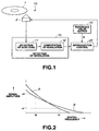
- FIG. 1 is a schematic block diagram of an information readout apparatus according to the invention and adapted to read out information from an optical disk, illustrating its configuration.
- the information readout apparatus 10 is adapted to irradiate a light beam to an optical disk 1 that is a recording medium having a recording layer and a readout layer by means of head 2 and read the information recorded on the recording layer by opening a detection window (aperture) smaller than the area irradiated by the light beam on the readout layer.
- the information readout apparatus determines the resolution by means of resolution detecting section 15 on the basis of the level of the signal read out from the optical disk 1 by means of the head 2.
- the resolution detecting section 15 has a signal level detection circuit 11 and a resolution computation circuit 12, of which the signal level detection circuit 11 detects the level of the signal read out from the optical disk 1 and the resolution computation circuit 12 computationally determines the resolution on the basis of the signal level and informs the readout control circuit with the resolution.
- Reference value output circuit 13 outputs reference value K that provides a target for controlling the resolution and readout control circuit 20 controls the readout power of the light beam from the head 2 so as to make the resolution as detected by the resolution detecting section 15 come closer to the reference value K.
- FIG. 2 is a graph illustrating the relationship between the spatial frequency and the signal amplitude.
- curve A represents the performance of a disk showing an ordinary resolution level
- curve B represents the performance of a super resolution disk showing a super resolution level.
- v1/v2 provides a value that corresponds to the signal resolution, a greater value of v1/v2 indicating a higher resolution.
- the resolution can be detected by detecting the ratio of two different spatial frequencies of f1 and f2 or that of two different signal levels v1/v2, which is equal to the ratio of the signal amplitudes, of two signals with different mark lengths.
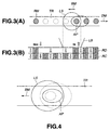
- FIGS. 3A and 3B schematically illustrate the theory underlying an MSR disk of the RAD system, of which FIG. 3A is a schematic plan view of the MSR disk and FIG. 3B is a schematic cross sectional view of the MSR disk.
- the disk-shaped recording medium comprises an exchange-coupled two-layer film having a recording layer RC and a readout layer RD.
- the highest temperature area is located at a position slightly displaced to the rear from the center of the light spot light source because of the difference between the rate of relative movement of the light beam in the direction of arrow BM and the rate of thermal diffusion of the recording medium.
- the highest temperature area is used as the detection window (aperture) AP, or the readout area, and the low temperature area located in front of the light beam is masked.
- the RAD system requires an externally applied readout magnetic field Hr and an initial magnetic field Hini and the readout layer RD is initialized before the readout operation by applying the initial magnetic field Hini in front of the light spot LS along recording track TR.
- the initialized part of the readout layer enters the light spot LS, one or more than one recorded bits (as magnetized upward in FIG. 3B) of that part are transferred to the readout layer RD by means of the externally applied readout magnetic field Hr in the hot detection window (aperture) AP and then read out.
- FIG. 4 is a schematic plan view of light spot LS formed by irradiating a light beam on track TR of a super resolution disk of the RAD system and its vicinity.
- the aperture (detection window) AP changes its size as a function of the readout power as indicated by the broken lines in FIG. 4. More specifically, the smaller the readout power, the smaller the aperture AP. Differently stated, the greater the readout power, the greater the aperture AP.
- FIG. 5 is a graph illustrating the signal resolution SR, the error rate ER, the signal amplitude SA and the cross talk CT relative to the readout power of a super resolution disk of the RAD system.
- the signal amplitude SA remains large once the readout power exceeds a certain level to provide a satisfactory C/N (carrier/noise) level, while the error rate ER falls as the readout power rises.
- the signal resolution SR also falls as the readout power rises because, in the case of the RAD system, the aperture increases as the readout power rises. When the readout power rises further, the aperture becomes almost as large as the light spot formed by the light beam to consequently reduce the resolution and make the optical disk no longer show the super resolution performance and both the cross talk CT from adjacent tracks and the error rate ER increase. Therefore, in the case of a super resolution disk of the RAD system, the signal resolution SR is inversely proportional to the readout power. Besides, there exists a readout power level that minimizes the error rate ER.
- the signal resolution corresponding to this readout power level takes the above described reference value K that provides the target value for controlling the readout power.
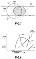
- FIGS. 6A and 6B schematically illustrate the theory underlying an MSR disk of the FAD system, of which FIG. 6A is a schematic plan view of the MSR disk and FIG. 6B is a schematic cross sectional view of the MSR disk.
- FIGS. 6A and 6B when a light beam is irradiated onto the disk-shaped recording medium that is moving in the sense of arrow DM as the disk is driven to turn, the highest temperature area is located at a position slightly displaced to the rear from the center of the light spot light source because of the difference between the rate of relative movement of the light beam in the direction of arrow BM and the rate of thermal diffusion of the recording medium.
- the highest temperature area becomes masked area MS and the low temperature area located in front of the light beam becomes the detection window (aperture) AP, or the readout area. Since the masked area MS shows an elliptic contour, the detection window (aperture) AP shows the contour of a crescent.
- a super resolution optical disk of the FAD system comprises an exchange-coupled three-layer film having a recording layer RC, a switching layer SW and a readout layer RD.
- a readout magnetic field Hr is externally applied and the magnetization of the high temperature area behind the light beam is directed to a single direction to form a masked area MS. Then, one or more than one recorded bits of the cold detection window AP located in a front part of the beam are read out.
- FIG. 7 is a schematic plan view of light spot LS formed by irradiating a light beam on track TR of a super resolution disk of the FAD system and its vicinity.
- the aperture (detection window) AP changes its size as a function of the readout power as indicated by the broken lines in FIG. 4. More specifically, the smaller the readout power, the smaller the masked area MS. Differently stated, the greater the readout power, the greater the masked area MS.
- FIG. 8 is a graph illustrating the signal resolution SR, the error rate ER, the signal amplitude SA and the cross talk CT relative to the readout power of a super resolution disk of the FAD system.
- the signal amplitude SA remains large once the readout power exceeds a certain level to provide a satisfactory C/N (carrier/noise) level, while the error rate ER falls as the readout power rises.
- the signal resolution SR rises as the readout power rises because, in the case of the FAD system, the masked area MS increases to reduce the detection window (aperture) as the readout power rises.
- the cross talk CT increases and eventually all the area within the light spot becomes the masked area to make it no longer possible to read out signals there.
- the signal resolution corresponding to the readout power level that minimizes the error rate ER takes the above described reference value K that provides the target value for controlling the readout power.
- FIGS. 9A and 9B schematically illustrate the theory underlying an MSR disk of the double mask system, of which FIG. 9A is a schematic plan view of the MSR disk and FIG. 9B is a schematic cross sectional view of the MSR disk.
- the double mask system is realized by combining the RAD system and the FAD system.
- the highest temperature area is located at a position slightly displaced to the rear from the center of the light spot light source because of the difference between the rate of relative movement of the light beam in the direction of arrow BM and the rate of thermal diffusion of the recording medium. Then, a low temperature area in a front part of the light beam becomes the first masked area MS1 and the second masked area MS2 is formed in the above high temperature area. The area located between the two masked areas MS1 and MS2 becomes the detection window (aperture) AP.
- a super resolution optical disk of the double mask system comprises an exchange-coupled four-layer film having a recording layer RC, an intermediate layer INT, a subsidiary layer SUB and a readout layer RD.
- the double mask system uses an externally applied readout magnetic field Hr and an initial magnetic field Hini, of which the initial magnetic field Hini is applied in front of the light spot LS along recording track TR to initialize the readout layer RD before the readout operation.
- the initialized part of the readout layer RD enters the light spot LS, one or more than one recorded bits (as magnetized upward in FIG. 9B) of that part are transferred to the readout layer RD by means of the externally applied readout magnetic field Hr in the detection window (aperture) AP and then read out.
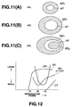
- FIG. 10 is a schematic plan view of light spot LS formed by irradiating a light beam on track TR of a super resolution disk of the double mask system and its vicinity, illustrating the relationship among the first and second masked areas MS1 and MS2 and the detection window (aperture) AP and also relative to the light spot LS.
- the relationship of these areas changes as the readout power changes in a manner as shown in (A) through (C) of FIG. 11.
- the readout power rises from a low level (P1) of (A) to a level (P2) slightly lower than the level of forming two masks as shown in (B) and then to a level (P3) where two masks are formed.
- FIG. 12 is a graph illustrating the signal resolution SR, the error rate ER, signal amplitude SA and the cross talk CT relative to the readout power of a super resolution disk of the double mask system.
- the signal resolution SR falls as the readout power rises as in the case of the RAD system.
- the signal resolution SR rises with the readout power as in the case of the FAD system.
- the error rate ER falls as the readout power rises from a low level and keeps on falling while the readout power goes up above the P2 level.
- the error rate ER reaches the lowest point when the readout power gets to a certain level. Two masks already exists at this point. Thereafter, the error rate ER rises as the readout power increases.
- the signal resolution corresponding to the readout power level that minimizes the error rate ER takes the above described reference value K that provides the target value for controlling the readout power.
- MSR magnetic super resolution
- SSR phase change super resolution
- RSR ROM super resolution
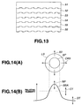
- FIG. 13 is a schematic illustration of the structure of a ROM super resolution (RSR) disk.
- the disk of FIG. 13 comprises a substrate 51, a protection layer 52, a Ge 2 Sb 2 Te 5 layer 53, another protection layer 54, a reflection layer 55 and still another protection layer 56 arranged in the above mentioned order. It becomes adapted to super resolution readout as a high temperature area is masked as in the case of the FAD system.
- a laser beam is irradiated onto a chalcogenide film such as the Ge 2 Sb 2 Te 5 layer 53 to form a light spot there, an area of the light spot heated by the light beam becomes molten to change its refractive index and start operating as mask that absorb light.
- the area in the light spot other than the mask of the Ge 2 Sb 2 Te 5 layer 53 forms a detection window (aperture) so that the information recorded in the reflection layer 55 can be read out through the detection window.
- a detection window aperture
- PSR phase change super resolution
- the reflection layer 55 is replaced by a recording layer, otherwise it is structurally identical with a ROM disk shown in FIG. 13.
- the signal resolution, the error rate, the signal amplitude and the cross talk relative to the readout power of a ROM disk or a PSR disk are same as those shown in FIG. 8 and hence will not be discussed here any further.
- the signal amplitude, the cross talk and the spatial frequency changes as the size and position of the aperture and those of the mask are changed by the readout power so that consequently, the optimal area for data detection will be quite limited.
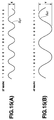
- FIG. 14 is a schematic illustration of the parameters that affect the detection window (aperture).
- (A) shows a schematic plan view of light spot LS on a recording medium formed by irradiating a light beam and its vicinity and (B) shows the temperature curve of the area shown in (A).
- the temperature curve moves in the directions indicated by the arrows to change the aperture AP as the readout power RP changes.
- the aperture AP is changed not only by the change in the readout power RP but also by the change in the transfer temperature CT at which the data is transferred from the recording layer to the readout layer, said transfer temperature CT representing the sensitivity of the recording medium, and the change in the temperature of the recording medium DT.
- the aperture AP is also changed by the strain of the light beam BSR caused by the effect of tilting or defocussing.
- These parameters can be optimized by detecting the factor such as the resolution that can optimize the frequency of the signal that is most related to the aperture size and optimizing the detected factor. This process of optimization can be applied not only to opto-magnetic disks but also to super resolution disks of any type.
- Controlling the resolution so as to make it optimized when detecting data refers to optimization of the aperture. More specifically, the resolution that minimizes the jitter or the error rate at the time of data detection is determined and selected as reference value or target value for controlling the readout power so as to optimize the aperture.
- the levels of the signals respectively representing so many recording marks that have different lengths are detected and compared with each other and the readout power is so controlled as to make the outcome of the comparison become close to a predetermined reference value in order to carrying out the readout operation always in the best condition.
- the unit time of the channel bit of a signal (the clock period of the channel bit) is T
- the signal S 2ST of the mark having a mark length of 2T shown in FIG. 15A is a signal obtained by reproducing a data showing a pattern of alternately arranged "00s" and "11s" in the NRZ format
- the signal S 4ST of the mark having a mark length of 4T shown in FIG. 15B is a signal obtained by reproducing a data showing a pattern of alternately arranged "0000s" and "1111s".
- the read out signal may show a peak value at a position different from the clock position for data detection depending on the modulation system and the demodulation system. If the peak has to be detected for such a signal, an additional signal processing procedure requiring the use of a clock different from the clock for data detection will have to be followed. Then, the hardware adapted to such a procedure will inevitably have a complex configuration and/or the load of following the signal processing procedures will be considerable. Additionally, there may be patterns that do not appear in the data to be read out.
- the patterns that do not appear in the data are those of the mark lengths to be detected such as 2T and 4T as described above
- the redundancy relative to the data will inevitably increase.
- the resolution is detected on the level of the signal to be read out. More specifically, two techniques may be used for detecting the resolution. With the first technique, the difference X between sampled value Y close to the peak value and the sampled value of the adjacent sampling point is determined for the read out waveform of an isolated mark in the recorded data of, for instance, the 2-7 NRZ modulation system that is separated from any other marks and the ratio X/Y is used as resolution.
- the second technique utilizes the asymmetry of the recorded mark and the ratio of the average level (center level) X to the saturation level Y of the read out signal, or X/Y, is used as resolution.
- the resolution that optimizes the detection window (aperture) is used as reference value (or target value) K and the power (the readout power) of the laser emitting elements is so controlled as to make the resolution (the ratio of the amplitudes X/Y) become close to the reference value K.
- the reference value K of resolution that corresponds to the situation where the detection window is optimized can be obtained by reading out the information written on a predetermined area (e.g., a control track) of the optical disk for the reference value K.
- a test readout operation is conducted on a predetermined test recording area (e.g., a test track), while changing the readout power, at the loading time of the optical disk or at appropriate regular time intervals to determine the jitter or the error rate and also the point that minimizes the jitter or the error rate on the basis of the read out data so that the ratio X/Y may be obtained as reference value K.
- a test readout operation is conducted, while changing the readout power, and the dispersion of the signal level near each peak of signal level distribution is determined so that the ratio X/Y that is obtained when the sum of the dispersions is minimized may be used as reference value K.
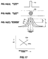
- FIG. 16 is a schematic illustration of the theory underlying the first embodiment of information readout apparatus according to the invention to which the above first technique is applied.
- (A) shows the waveform of the recorded data of an isolated mark and its vicinity, where isolated pulse P 0 having a width of 2T representing the shortest interval for inversion is observable.
- (B) shows the isolated mark M 0 that can be obtained by recording the data of (A) on a recording track of the optical disk.
- (C) shows three different readout waveforms Sa, Sb and Sc that can be obtained by reading out the isolated mark M 0 with different levels of readout power.
- the ratio X/Y is detected as the value representing the resolution. Then, the resolution X/Y with optimal readout power is selected as target value (reference value) K in advance and the readout power is so servo-controlled as to make the ratio X/Y detected at each sampling point become close to the target value K.
- FIG. 18 is a schematic block diagram of an optical disk apparatus to which the first embodiment is applied.
- FIG. 19 is a flow chart of the operation of the optical disk apparatus of FIG. 18.
- a super resolution optical disk 1 is used as optical disk in the optical disk apparatus 10 of FIG. 18.
- a light beam (laser beam) is emitted from head 2 onto the optical disk 1 in Step S1 and the reflected light beam from the optical disk 1 is detected by photoelectric converter (photodetector) 2a, which produces a readout signal out of the light beam (photoelectric conversion of Step S2 in FIG. 19) and sends it to equalizing circuit (equalizer) 17.
- the equalizing circuit 17 equalizes (the waveform) of the readout signal.
- the equalizing circuit 17 may typically use a cosine equalizer so that its equalizing characteristics (e.g., equalizing gain) can be controlled.
- the readout signal output from the equalizing circuit 17 is sent to signal level detecting circuit 11 of the resolution detecting section 15 and also to data detecting circuit 21, which will be described hereinafter.
- the signal level detecting circuit 11 detects the signal level by way of sampling (Step S4) and the resolution computing circuit 12 computationally determines the resolution (Step S5).
- the signal representing the obtained resolution is sent to comparator circuit 14, which is also fed with reference value K output from reference value output circuit 13 (Step S6).
- the comparator circuit 14 compares the resolution obtained from the resolution computing circuit 12 of the resolution detecting section 15 and the reference value K obtained from the reference value output circuit 13 (Step S7) and the signal representing the outcome of the comparison, or the difference between the resolution and the reference value K, is sent to band dividing circuit 19.
- the band dividing circuit 19 divides the signal representing the resolution, or the difference between the resolution and the reference value K to be more accurate, into a DC component, a low frequency component and a high frequency component (Step S8), of which the DC component and the low frequency component are sent to readout power control circuit 16 and used for controlling the readout power (Step S9), while the high frequency component is sent to the equalizing circuit 17 and used to control the equalizing operation (Step S10).
- the low range factor (the DC component and the low frequency component) including the ambient temperature of the recording medium that changes only little with time is used to control the readout power while the high range factor is used to control the equalizing performance including the equalization gain.
- the readout signal from the equalizing circuit 17 is sent to data detection circuit 21, which is typically adapted to detect (read out) data by detecting partial responses PR (1, 2, 1). More specifically, in the case of the detection of PR (1, 2, 1) of a 1-7 NRZI modulation signal, the signal level is made to be quaternary and a binary data is read out typically by means of Viterbi decoding (maximum likelihood decoding).
- the read out data from the data detection circuit 21 is sent to ECC (error correction code) error correcting circuit 22 for the purpose of error correction and then taken out as output data.
- ECC error correction code
- bit error information from the ECC error correcting circuit 22 is sent to CPU 23 for the purpose of selecting reference value K and the resolution from the resolution computing section 12 obtained when the bit error rate is minimal is selected as reference value K, which reference value K is then output from the reference value output circuit 13 and sent to the comparator circuit 14.
- the resolution can be detected by using only the readout signal of the isolated mark prepared and recorded on the recording medium in advance so that, unlike the prior art, it is no longer necessary to provide a plurality of recording mark patterns having respective lengths that are different from each other so that the level of redundancy and the reduction of the recording capacity of the disk can be minimized.
- it is necessary to use a clock dedicated to detect the amplitude of the read out signal having a specific mark length.
- This embodiment is adapted to detect the resolution on the basis of the ratio of the average level (center level) X to the saturation level Y of the readout signal.
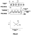
- FIG. 20 is a schematic illustration of the theory underlying the second embodiment of the invention, which is applied to an optical disk readout apparatus.
- (A) shows a recorded mark RM recorded on a recording track TR and, when a light beam is irradiated on the recorded mark RM with two different readout power levels, two apertures AP 1 and AP 2 are formed with respective sizes that are different from each other.
- (B) shows three different readout waveforms Sa, Sb and Sc obtained as a result of reading out the recorded mark RM as shown in (A) of FIG. 20 and corresponding to three different levels of readout power. Of each of the waveforms shown in (B) of FIG.
- the saturated value of the readout signal level (saturation level) is expressed by Y and the ratio of the center level (average level) of the readout signal to the saturation level, or X/Y, is detected as value corresponding to the resolution.
- the resolution X/Y for an optimal readout power level is selected in advance as target value (reference value) K and the readout position is so serve-controlled as to make the ratio X/Y as detected during the readout operation become close to the target value K.
- the optical disk readout apparatus to which the second embodiment of the invention is applied may have a configuration same as the one illustrated in FIG. 18. Then, referring to FIG. 18, the signal level detection circuit 11 of the resolution detecting section 15 may be used to detect the saturation level and the average level of the readout signal, while the resolution computing circuit 12 may be used to computationally determines the resolution on the basis of the level ratio of X/Y.
- the resolution can be detected on the basis of the saturation level and the average level of the signal read out for an ordinary data so that, unlike the prior art, it is no longer necessary to record in advance signals having specific respective mark lengths on the optical disk so that the level of redundancy and the reduction of the recording capacity of the disk can be minimized because the resolution can be detected on the basis of the average level and the saturation levels of the signals of the ordinary signals read out from the recording medium.
- a clock dedicated to detect the amplitude of the read out signal having a specific mark length and accurately obtain resolution-related information on a stable basis.
- the aperture is corrected by dividing the frequency and combining the control of the readout power and the control of the equalizing operation so that the accuracy and the stability can be further improved.
- recording media to which the present invention is applicable is not limited to magnetic super resolution disks and includes phase change super resolution disks and ROM super resolution disks as well as recording media other than disks.
Landscapes
- Physics & Mathematics (AREA)
- Optics & Photonics (AREA)
- Optical Recording Or Reproduction (AREA)
- Optical Head (AREA)
Applications Claiming Priority (2)
| Application Number | Priority Date | Filing Date | Title |
|---|---|---|---|
| JP11233241A JP2001056939A (ja) | 1999-08-19 | 1999-08-19 | 情報再生装置及び方法 |
| JP23324199 | 1999-08-19 |
Publications (1)
| Publication Number | Publication Date |
|---|---|
| EP1077449A1 true EP1077449A1 (en) | 2001-02-21 |
Family
ID=16951990
Family Applications (1)
| Application Number | Title | Priority Date | Filing Date |
|---|---|---|---|
| EP00117817A Withdrawn EP1077449A1 (en) | 1999-08-19 | 2000-08-18 | Information readout apparatus and information readout method |
Country Status (3)
| Country | Link |
|---|---|
| US (1) | US6845074B1 (enExample) |
| EP (1) | EP1077449A1 (enExample) |
| JP (1) | JP2001056939A (enExample) |
Cited By (3)
| Publication number | Priority date | Publication date | Assignee | Title |
|---|---|---|---|---|
| US7903511B2 (en) | 2005-09-05 | 2011-03-08 | Nec Corporation | Optical information reproducing method, optical information reproducing device, and optical information recording medium for performing reproduction of information by using laser beams |
| EP1964119B1 (en) * | 2005-12-20 | 2011-10-26 | Samsung Electronics Co., Ltd. | Method and apparatus to determine an optimum reproducing condition on an optical recording medium |
| CN116402691A (zh) * | 2023-06-05 | 2023-07-07 | 四川轻化工大学 | 基于图像特征快速拼接的图像超分辨率方法和系统 |
Families Citing this family (5)
| Publication number | Priority date | Publication date | Assignee | Title |
|---|---|---|---|---|
| US6925575B2 (en) * | 2002-04-05 | 2005-08-02 | Intel Corporation | Selectable clocking synchronization of a parallel-to-serial converter and memory |
| JP4253724B2 (ja) * | 2003-10-31 | 2009-04-15 | 独立行政法人産業技術総合研究所 | レーザビームの再生パワーの決定方法およびデータ記録再生装置 |
| JP4657338B2 (ja) * | 2008-10-09 | 2011-03-23 | シャープ株式会社 | 光情報記録媒体再生装置、光情報記録媒体再生プログラム、およびコンピュータ読み取り可能な記録媒体 |
| FR2938065B1 (fr) * | 2008-11-05 | 2012-05-25 | I2S | Procede de numerisation de livres en trois dimensions par ondes terahertz. |
| TWI391918B (zh) * | 2009-06-15 | 2013-04-01 | Novatek Microelectronics Corp | 資料復原裝置與方法 |
Citations (6)
| Publication number | Priority date | Publication date | Assignee | Title |
|---|---|---|---|---|
| EP0524315A1 (en) * | 1991-02-13 | 1993-01-27 | Sony Corporation | Method for reproducing signal in optically recording medium |
| US5483513A (en) * | 1993-08-25 | 1996-01-09 | Sharp Kabushiki Kaisha | Recording state detecting apparatus and optical recording medium |
| US5617400A (en) * | 1994-08-29 | 1997-04-01 | Sharp Kabushiki Kaisha | Magneto-optical recording and reproducing apparatus with layer aperture control |
| EP0800169A2 (en) * | 1996-04-05 | 1997-10-08 | Fujitsu Limited | Information reproducing method and information reproducing/recording method for magneto-optical recording medium and magneto-optical reproducing device |
| JPH11224424A (ja) * | 1998-02-05 | 1999-08-17 | Sony Corp | 光ディスク再生制御装置 |
| WO1999053489A1 (en) * | 1998-04-10 | 1999-10-21 | Sony Corporation | Information reproducing device and method |
Family Cites Families (3)
| Publication number | Priority date | Publication date | Assignee | Title |
|---|---|---|---|---|
| WO1993017417A1 (fr) | 1992-02-19 | 1993-09-02 | Sony Corporation | Support d'enregistrement optique, son procede d'enregistrement, son procede de reproduction et procede pour produire des signaux d'erreur de poursuite |
| US5633854A (en) | 1992-02-19 | 1997-05-27 | Sony Corporation | Methods and apparatus for reproducing data recorded on an optical recording medium |
| US6278667B1 (en) * | 1998-01-30 | 2001-08-21 | Seagate Technology, Inc. | System and method for light power control in a magneto-optical drive |
-
1999
- 1999-08-19 JP JP11233241A patent/JP2001056939A/ja active Pending
-
2000
- 2000-08-10 US US09/636,053 patent/US6845074B1/en not_active Expired - Fee Related
- 2000-08-18 EP EP00117817A patent/EP1077449A1/en not_active Withdrawn
Patent Citations (6)
| Publication number | Priority date | Publication date | Assignee | Title |
|---|---|---|---|---|
| EP0524315A1 (en) * | 1991-02-13 | 1993-01-27 | Sony Corporation | Method for reproducing signal in optically recording medium |
| US5483513A (en) * | 1993-08-25 | 1996-01-09 | Sharp Kabushiki Kaisha | Recording state detecting apparatus and optical recording medium |
| US5617400A (en) * | 1994-08-29 | 1997-04-01 | Sharp Kabushiki Kaisha | Magneto-optical recording and reproducing apparatus with layer aperture control |
| EP0800169A2 (en) * | 1996-04-05 | 1997-10-08 | Fujitsu Limited | Information reproducing method and information reproducing/recording method for magneto-optical recording medium and magneto-optical reproducing device |
| JPH11224424A (ja) * | 1998-02-05 | 1999-08-17 | Sony Corp | 光ディスク再生制御装置 |
| WO1999053489A1 (en) * | 1998-04-10 | 1999-10-21 | Sony Corporation | Information reproducing device and method |
Non-Patent Citations (1)
| Title |
|---|
| PATENT ABSTRACTS OF JAPAN vol. 1999, no. 13 30 November 1999 (1999-11-30) * |
Cited By (4)
| Publication number | Priority date | Publication date | Assignee | Title |
|---|---|---|---|---|
| US7903511B2 (en) | 2005-09-05 | 2011-03-08 | Nec Corporation | Optical information reproducing method, optical information reproducing device, and optical information recording medium for performing reproduction of information by using laser beams |
| EP1964119B1 (en) * | 2005-12-20 | 2011-10-26 | Samsung Electronics Co., Ltd. | Method and apparatus to determine an optimum reproducing condition on an optical recording medium |
| CN116402691A (zh) * | 2023-06-05 | 2023-07-07 | 四川轻化工大学 | 基于图像特征快速拼接的图像超分辨率方法和系统 |
| CN116402691B (zh) * | 2023-06-05 | 2023-08-04 | 四川轻化工大学 | 基于图像特征快速拼接的图像超分辨率方法和系统 |
Also Published As
| Publication number | Publication date |
|---|---|
| US6845074B1 (en) | 2005-01-18 |
| JP2001056939A (ja) | 2001-02-27 |
Similar Documents
| Publication | Publication Date | Title |
|---|---|---|
| US5808988A (en) | Reproduction of optical information by one-beam optics with reduced crosstalk as recorded in multi-phases and multi-levels at staggered lattice points, and apparatus and recording medium therefor | |
| US6845074B1 (en) | Information readout apparatus and information readout method | |
| KR100434834B1 (ko) | 광 재생 장치 및 그 제어 방법 | |
| US6809994B2 (en) | Method for controlling radiation power of domain expansion type magneto-optical recording medium | |
| US6459669B1 (en) | Information reproducing apparatus and information reproducing method | |
| US5206853A (en) | Apparatus and method for detecting intersymbol interference | |
| JP2005518058A (ja) | 磁区拡大記録媒体及び記録担体を用いた利用のための位相及び/又はコピーウィンドウの制御のための方法及び装置 | |
| JP4451004B2 (ja) | 光再生装置 | |
| US20030035348A1 (en) | Magneto-optical recording medium and magneto-optical recording and reproducing device | |
| US6754141B1 (en) | Recording medium, method for recording and reproducing data using the medium, and magneto-optical recording apparatus | |
| US7791999B2 (en) | Writing condition optimizing method and apparatus, and optical recording medium | |
| US20020191497A1 (en) | Magneto-optical recording for improved domain expansion reading | |
| US7385883B2 (en) | Stray field equalization for improved domain expansion reading | |
| US20020176334A1 (en) | Method and system for generating a tracking error signal | |
| JP2000163748A (ja) | 情報記録方式および情報記録再生装置 | |
| EP1706870B1 (en) | Method and apparatus for controlling a readout parameter during reading | |
| JP4338903B2 (ja) | 光ディスク記録装置およびその調整方法 | |
| JP2762635B2 (ja) | 光記録再生方式 | |
| US20050078563A1 (en) | Read-out control for use with a domain expansion recording medium | |
| JP2002319231A (ja) | 光学的情報記録再生装置 | |
| JPWO1999053489A1 (ja) | 情報再生装置及び方法 | |
| JP2005063521A (ja) | 光磁気記録再生方法及び装置 | |
| JPH06349128A (ja) | 光磁気記録方式 | |
| JPH0612718A (ja) | 光磁気情報記録再生装置 |
Legal Events
| Date | Code | Title | Description |
|---|---|---|---|
| PUAI | Public reference made under article 153(3) epc to a published international application that has entered the european phase |
Free format text: ORIGINAL CODE: 0009012 |
|
| AK | Designated contracting states |
Kind code of ref document: A1 Designated state(s): DE FR GB |
|
| AX | Request for extension of the european patent |
Free format text: AL;LT;LV;MK;RO;SI |
|
| 17P | Request for examination filed |
Effective date: 20010621 |
|
| AKX | Designation fees paid |
Free format text: DE FR GB |
|
| 17Q | First examination report despatched |
Effective date: 20071001 |
|
| STAA | Information on the status of an ep patent application or granted ep patent |
Free format text: STATUS: THE APPLICATION IS DEEMED TO BE WITHDRAWN |
|
| 18D | Application deemed to be withdrawn |
Effective date: 20100302 |