EP1076003A1 - Device for attaching an object, in particular a bag, onto a motorcycle tank - Google Patents
Device for attaching an object, in particular a bag, onto a motorcycle tank Download PDFInfo
- Publication number
- EP1076003A1 EP1076003A1 EP00402165A EP00402165A EP1076003A1 EP 1076003 A1 EP1076003 A1 EP 1076003A1 EP 00402165 A EP00402165 A EP 00402165A EP 00402165 A EP00402165 A EP 00402165A EP 1076003 A1 EP1076003 A1 EP 1076003A1
- Authority
- EP
- European Patent Office
- Prior art keywords
- support
- attachment means
- motorcycle
- tank
- pin
- Prior art date
- Legal status (The legal status is an assumption and is not a legal conclusion. Google has not performed a legal analysis and makes no representation as to the accuracy of the status listed.)
- Granted
Links
Images


Classifications
-
- B—PERFORMING OPERATIONS; TRANSPORTING
- B62—LAND VEHICLES FOR TRAVELLING OTHERWISE THAN ON RAILS
- B62J—CYCLE SADDLES OR SEATS; AUXILIARY DEVICES OR ACCESSORIES SPECIALLY ADAPTED TO CYCLES AND NOT OTHERWISE PROVIDED FOR, e.g. ARTICLE CARRIERS OR CYCLE PROTECTORS
- B62J9/00—Containers specially adapted for cycles, e.g. panniers or saddle bags
- B62J9/20—Containers specially adapted for cycles, e.g. panniers or saddle bags attached to the cycle as accessories
- B62J9/25—Containers specially adapted for cycles, e.g. panniers or saddle bags attached to the cycle as accessories to the fuel tank, e.g. magnetic tank bags
Definitions
- the invention relates to accessories for motorcycles and analogues.
- It relates more particularly to a device for fixing an object, in particular a satchel, to a motorcycle tank.
- tank guards that take up the shape of the tank and that protect it from scratches and fix different saddlebags.
- installing and uninstalling such tank guards are long enough and do not allow to fix other items on the motorcycle.
- the biker wants to fill his tank, so he is forced remove the bag to gain access to the filler cap, or keep it by hand.
- the object of the invention is in particular to overcome the drawbacks cited above.
- It aims in particular to provide a fixing device forming universal support and allowing to fix different objects, not just saddlebags, on the tank keeping them in any desired position.
- the invention also aims to provide such a device for fixing that allows installation and uninstallation object fast.
- the invention provides a device for fixing the type defined above, which includes its own support to be secured to a fixed element of the motorcycle, in front of the tank, and comprising first attachment means suitable for cooperating in articulation with second means of attachment to the object, to allow rotate the object around an axis and place it selectively, either in a low position close to the tank, or in at least one raised position away from the tank.
- the device of the invention essentially comprises a support which is fixed to a fixed element of the motorcycle, in particular to the chassis, and which makes it possible to fix different types of objects by offering an articulated mounting, which allows rotate the object and place it in a position chosen from an infinity of positions.
- This device makes it possible to fix different objects such as, for example, saddlebags of all types, but also others products such as a briefcase, a first aid kit, a DIY kit, a positioning system, a helmet, lock, mobile phone, road map, an air reflection bubble, a device for protecting legs against the rain, etc.
- the device comprises locking means suitable for locking the object in a chosen position.
- the support is designed to remain permanently on the motorcycle, while that the second attachment means are easily separable first attachment means to allow mounting or disassembly of the object.
- the support comprises a first part, or lower part, suitable for being fixed on the motorcycle and, a second part, or upper part, which wear the first means of attachment.
- the first part and the second part can be formed a single piece or two pieces assembled between they.
- the first attachment means include two spaced legs forming part of the support in which are screwed respectively two threaded axes arranged coaxially for define the pivot axis and directed outwards, being provided with respective clamping members, while the second attachment means include two spaced forks adapted to be engaged each around a threaded axis and in the space defined between the tab and the clamping member correspondents.
- the first attachment means include two spaced legs forming part of the support, one of which carries a pin and the other of which receives a threaded axis provided with a tightening, so that the threaded spindle and axis are arranged coaxially to define the pivot axis, while the second attachment means comprise two spaced legs, one of which has a hole for engagement of the spindle and the other has the shape of a clean fork to be engaged around the threaded axis and in space delimited between the tab and the corresponding clamping member.
- the first attachment means comprise a tube comprising a split part and a hose clamp surrounding said split part, the tube extending in the direction of the axis pivoting, while the second attachment means include a rod suitable for being engaged in the tube and be locked in position by tightening the collar.
- the first attachment means include two spaced legs forming part of the support, one of which carries a ratchet reversible with a first spindle and the other carries a second pin, these pins being arranged coaxially to define the pivot axis, while the latter attachment means include two clean spaced forks to receive the first pin and the second respectively brooch.
- the first attachment means include two spaced legs forming part of the support, one of which carries a ratchet reversible with a first spindle and the other carries a second pin, these pins being integral with a block of locking and being arranged coaxially to define the pivot axis, while the second attachment means include a rod suitable for engaging in a slot in the locking block and to be held by a body locking.
- the support is made specifically according to the motorcycle which it is intended for, while the earliest means attachment and the second attachment means are standard.
- the device includes a damper pad suitable for being placed on the object to come to rest preferably against the tank filler cap in the down position the object.
- the device represented in FIG. 1 comprises a support 10 suitable for being secured to a fixed element, in the example the chassis 12, of a motorcycle, in front of the fuel 14 of the latter.
- the device is used for fixing an object 16, here a satchel.
- Support 10 includes first attachment means 18 adapted to cooperate articulated with second fastening means 20 integral of the bag 16 to allow this pivoting object around an axis XX which extends transversely and horizontally, with the motorcycle standing.
- the bag 16 can thus be placed selectively, either in a low position close to the reservoir 14 (FIG. 1), either in at least one raised position away from the tank (figure 2), allowing an infinite number of positions.
- the lower position of Figure 1 corresponds to a transport position
- the upper position of figure 2 corresponds to a position retractable which provides access to the stopper filling 22 of the tank to allow the full of fuel.
- the bag 16 has a shaped underside 24 which has a shape homologous to that of the upper face 26 of reservoir 14 to allow cooperation of shapes in the lower position of figure 1.
- the device comprises a shock absorbing pad 28 placed on the lower face 24 of the bag to come into abutment, in the low position, against the filler cap 22 or a other part of the tank 14.
- the raised position corresponds to the position of use or transport, while the lower position corresponds to a position retracted.
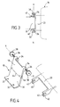
- the support 10 comprises a lower part 30 which has the shape of an L-shaped leg provided with two holes 32 for fixing to the chassis of the motorcycle and which carries the attachment means 18.
- these attachment means 18 comprise two spaced legs 34 into which are respectively screwed two threaded axes 36 arranged coaxially to define the axis pivot XX.
- These threaded axes 36 are directed towards outside and are fitted with clamping members formed by respective drive buttons 38 (e.g. knobs) allowing to screw or unscrew the axes 36 in each time moving button 38 closer or further away from the leg 34 which corresponds to it.
- the second attachment means 20 which are integral with the bag 16 include two spaced forks 40 defining two respective openings 42 and suitable for engaging each around a threaded axis 36 and in the space delimited between the tab 34 and the corresponding button 38.
- the bag 16 is secured to the support and can be immobilized in a desired position.
- attachment means offer a fixation of the quick type allowing the bag to be installed in a desired position, and also to uninstall it.
- the support 10 is permanently fixed to the chassis (or other fixed part) by suitable fixing means which will be described later.
- the two parts of the support 10 are two separate pieces, joined by joining edges respective 44 and 46 which are joined together. These two parts are not intended to be separated by the biker.
- the biker So for installing or uninstalling the bag, the biker must perform a screwing or unscrewing on each of the buttons 38.
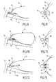
- the embodiment of FIG. 5 constitutes a variant from the previous one.
- the first attachment means 18 include two spaced apart legs 48, of rounded shape, one of which carries a pin 50, of short length, and the other receives a threaded pin 52 provided with a drive button 54, which are similar to the threaded pin 36 and the button 38 in the figure 4.
- the spindle 50 and the threaded axis 52 are arranged coaxially to define the pivot axis XX.
- the second attachment means 20 comprise two tabs spaced 56 and 58, the tab 56 being provided with a hole 60 for the engagement of the pin 50 and the other tab 58 has the shape a fork which is similar to a fork 40 in the figure 4. This fork is suitable for being engaged around the axis threaded 52, between the tab 48 and the drive button 54.
- Installing and uninstalling the object requires a screwing or unscrewing action at the touch of a button.
- the first ones attachment means 18 here comprise a tube 62 comprising a split part 64 and a clamp 66 surrounding this split part.
- the tube 62 is hollow and defines a passage extending in the direction of the pivot axis XX.
- the second attachment means 20 here comprise a connecting rod 69 carrying a transverse rod 70 suitable for being engaged completely in tube 62 until its end free 72 arrives at the split part 64 of the tube, in the region of the clamp 66.
- the latter includes an actuating handle 68 (FIGS. 6 and 7) which makes it possible to tighten the collar around the part split the tube by tightening the rod 70 and keeping it in the desired position.
- the locking or unlocking means are at left of the motorcycle when we look at this motorcycle in the direction of the motorcycle, i.e. from the rear to the front. This is the side where the biker descends or rises from his motorcycle.
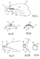
- the support 10 is fixed by two vertical screws 70 which serve to fix also a metal tab 72 of the reservoir 14 on the chassis 12 of the motorcycle.
- the two screws 70 are placed between the front of the tank and the steering column 74.
- the support 10 is fixed by two vertical screws 76 below the tank 14. These screws can be fixed either directly on the tank, either on the chassis.
- the support 10 is fixed by a vertical screw 78 which is used to fix a tab metallic 80 of the tank on the chassis of the motorcycle.
- the screw is on the central axis of the motorcycle.
- the support 10 is fixed by a horizontal screw 82 which passes through a tab 84 used for fixing the reservoir to the chassis 12 of the motorcycle.
- the support 10 includes an end 86 which is engaged in a space free 88 formed between the chassis 12 of the motorcycle and a underside 90 of the tank.
- This support can be held by a screw 92 making a counter-support between the chassis 12 and the underside of the tank ( Figure 15), the screw having at its upper end a part rubberized 94 so as not to damage the tank.
- the support is held by a semi-rigid material 96 of the rubber type which compresses the part 86 of the support against the chassis 12.
- Figures 14 to 16 are suitable particularly to motorcycles with tanks lifts forward or for motorcycles whose tank is positioned by translation forwards. So, when the tank is replaced, it compresses the part semi-rigid or the end of the screw.
- the semi-rigid part 96 can be made by an expandable part with air tablet or any other liquid (tube type) allowing occupy all the space and press the support against the chassis of the motorcycle.
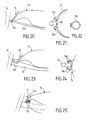
- the support 10 is fixed by a collar 98 around the column of direction 74 of the motorcycle. It is a split necklace comprising a clamping screw 100 ( Figures 18 and 19).
- Figures 20 and 21 applies to a motorcycle whose chassis includes at least one element 102, for example tubular.
- the support 10 is then fixed on an element 102 by a collar 104 (figure 20) or by two clamps 104 on two elements 102 of the chassis.
- the necklace 104 is shown in Figure 2.
- the support is fixed by screws 106 coming to tighten on two faces side 108 of the chassis.
- FIG. 25 applies to a motorcycle, the reservoir 14 of which comprises a fine part and rigid called gutter 110.
- the support is fixed by pinching this gutter 110 thanks to a screw 112 and the tank is then replaced. If the space between the chassis and the tank is weak, the support also carries on the chassis, which perfectly blocks this one.
- the first attachment means include two spaced legs 114, 116 forming part of the support 10.
- the tab 114 carries a reversible ratchet 118 similar to those of socket wrenches and having a lever 120 for reversing the direction of rotation. so it blocks rotation in one direction and allows rotation in the other direction, and vice versa when we change the position the joystick.
- the pawl has a section pin 122 square.
- the tab 116 carries a pin 124 of circular section arranged coaxially with pin 122 to define the axis pivot (XX).
- the second attachment means 20 comprise two spaced forks 126 and 128 suitable for receiving pins 122 and 124 respectively.
- the bag is positioned on the two pins 122 and 124 in a high position. Then the bag is lowered, the lever 120 being in a position allowing such movement so that 130 circular shapes of the legs 114 and 116 ( Figures 27 to 29) enter lights circular 132 of the second attachment means 20. Once in low position, the bag cannot be lifted and is immobilized. In the high position, the bag cannot descend and it only holds by gravity on the two pins.
- the angular position of the forms 130 must be adapted to the bag is fixed in the low position and free in high position.
- the second attachment means are suitable for this.
- the embodiment of Figure 33 is a variant of the previous one.
- the first means of attachment include two spaced legs 114 and 116 carrying respectively a reversible ratchet 118 provided with a pin 122 and a second pin 124.
- a locking block 134 of shape parallelepiped is integral with pins 122 and 124. the ratchet thus blocks block 134 once in a once in the other direction.
- Block 134 has a slot 136 and a locking member 138.
- the second attachment means comprise a rod 140 suitable for engaging in the slot 136 and to be maintained by the locking 138. This member 138 makes it possible to secure or separate the attachment means 18 and 20.
- the support of the invention is generally made to measure for each motorcycle model and when it can be in contact with a visible or invisible part of the tank, it has a foam so as not to damage it.
Abstract
Description
L'invention se rapporte aux accessoires pour motocyclettes et analogues.The invention relates to accessories for motorcycles and analogues.
Elle concerne plus particulièrement un dispositif pour la fixation d'un objet, en particulier d'une sacoche, sur un réservoir de motocyclette.It relates more particularly to a device for fixing an object, in particular a satchel, to a motorcycle tank.
Il est connu d'équiper une motocyclette d'un porte-bagages arrière, conçu essentiellement pour porter des bagages derrière la selle du passager ou bien sur cette selle.It is known to equip a motorcycle with a luggage rack rear, designed primarily to carry luggage behind the passenger seat or on this seat.
Ces porte-bagages peuvent aussi servir à fixer d'autres objets au moyen de sangles, tendeurs et analogues. Il en résulte alors un risque de déséquilibre de la motocyclette et l'inconvénient supplémentaire, dans certains cas, de ne pas permettre d'accueillir un passager car le porte-bagages empiète, sur certaines motos, sur la selle du passager.These racks can also be used to fix other objects by means of straps, tensioners and the like. It this results in a risk of imbalance of the motorcycle and the additional disadvantage, in some cases, of not accommodate a passenger because the luggage rack encroaches on certain motorcycles on the passenger saddle.
Sur de nombreuses motocyclettes, il n'existe pas de place suffisante pour un porte-bagages et le seul espace disponible se situe alors sur le réservoir.On many motorcycles, there is no room sufficient for a luggage rack and the only space available is then located on the tank.
Il existe aussi des protège-réservoirs qui reprennent la forme du réservoir et qui permettent de le protéger contre les rayures et de fixer différentes sacoches. Toutefois, l'installation et la désinstallation de tels protège-réservoirs sont assez longues et ils ne permettent pas de fixer d'autres objets sur la motocyclette. En outre, lorsque le motard veut remplir son réservoir, il est alors obligé d'enlever la sacoche pour avoir accès au bouchon de remplissage, ou de la maintenir à la main.There are also tank guards that take up the shape of the tank and that protect it from scratches and fix different saddlebags. However, installing and uninstalling such tank guards are long enough and do not allow to fix other items on the motorcycle. Furthermore, when the biker wants to fill his tank, so he is forced remove the bag to gain access to the filler cap, or keep it by hand.
Il est connu aussi de fixer des sacoches sur le réservoir par des aimants, des sangles, des tendeurs, etc... qui risquent d'endommager le réservoir. En outre, l'installation et la désinstallation de ces sacoches sont assez longues, notamment dans le cas d'une fixation par des sangles ou des tendeurs. De plus ces sacoches ne sont pas stables à grande vitesse et elles sont peu esthétiques.It is also known to fix saddlebags on the tank by magnets, straps, turnbuckles, etc ... which risk damage the tank. In addition, the installation and uninstalling these saddlebags are quite long, especially in the case of attachment by straps or tensioners. In addition, these bags are not stable at high speed and they are unsightly.
L'invention a notamment pour but de surmonter les inconvénients précités.The object of the invention is in particular to overcome the drawbacks cited above.
Elle vise en particulier à procurer un dispositif de fixation formant support universel et permettant de fixer différents objets, et non pas uniquement des sacoches, sur le réservoir en les maintenant dans une position désirée quelconque.It aims in particular to provide a fixing device forming universal support and allowing to fix different objects, not just saddlebags, on the tank keeping them in any desired position.
L'invention vise également à procurer un tel dispositif de fixation qui permet une installation et une désinstallation rapides de l'objet.The invention also aims to provide such a device for fixing that allows installation and uninstallation object fast.
Elle vise aussi à procurer un tel dispositif de fixation qui permet de fixer un grand nombre d'objets et qui, en outre, ne risque pas d'endommager le réservoir de la motocyclette.It also aims to provide such a fixing device which allows to fix a large number of objects and which, moreover, does not risk of damaging the motorcycle tank.
L'invention propose à cet effet un dispositif de fixation du type défini précédemment, lequel comprend un support propre à être solidarisé à un élément fixe de la motocyclette, en avant du réservoir, et comprenant des premiers moyens d'attache propres à coopérer à articulation avec des seconds moyens d'attache solidaires de l'objet, pour permettre de faire pivoter l'objet autour d'un axe et le placer sélectivement, soit dans une position basse proche du réservoir, soit dans au moins une position relevée éloignée du réservoir.To this end, the invention provides a device for fixing the type defined above, which includes its own support to be secured to a fixed element of the motorcycle, in front of the tank, and comprising first attachment means suitable for cooperating in articulation with second means of attachment to the object, to allow rotate the object around an axis and place it selectively, either in a low position close to the tank, or in at least one raised position away from the tank.
Ainsi, le dispositif de l'invention comprend pour l'essentiel un support qui est fixé à un élément fixe de la motocyclette, en particulier au châssis, et qui permet de fixer différents types d'objets en offrant un montage articulé, ce qui permet de faire pivoter l'objet et de le placer dans une position choisie parmi une infinité de positions. Thus, the device of the invention essentially comprises a support which is fixed to a fixed element of the motorcycle, in particular to the chassis, and which makes it possible to fix different types of objects by offering an articulated mounting, which allows rotate the object and place it in a position chosen from an infinity of positions.
Ce dispositif permet de fixer différents objets tels que, par exemple, des sacoches de tous types, mais aussi d'autres produits comme un attaché case, une trousse de secours, une trousse de bricolage, un système de positionnement, un casque, un antivol, un téléphone mobile, une carte routière, une bulle de réflexion d'air, un dispositif de protection des jambes contre la pluie, etc.This device makes it possible to fix different objects such as, for example, saddlebags of all types, but also others products such as a briefcase, a first aid kit, a DIY kit, a positioning system, a helmet, lock, mobile phone, road map, an air reflection bubble, a device for protecting legs against the rain, etc.
De préférence, le dispositif comprend des moyens de verrouillage propres à bloquer l'objet dans une position choisie.Preferably, the device comprises locking means suitable for locking the object in a chosen position.
Selon une autre caractéristique de l'invention, le support est conçu pour rester à demeure sur la motocyclette, tandis que les seconds moyens d'attache sont séparables facilement des premiers moyens d'attache pour permettre un montage ou un démontage de l'objet.According to another characteristic of the invention, the support is designed to remain permanently on the motorcycle, while that the second attachment means are easily separable first attachment means to allow mounting or disassembly of the object.
On prévoit alors avantageusement que le support comprend une première partie, ou partie basse, propre à être fixée sur la motocyclette et, une seconde partie, ou partie haute, qui porte les premiers moyens d'attache.It is then advantageously provided that the support comprises a first part, or lower part, suitable for being fixed on the motorcycle and, a second part, or upper part, which wear the first means of attachment.
La première partie et la deuxième partie peuvent être formées d'une pièce unique ou bien de deux pièces assemblées entre elles.The first part and the second part can be formed a single piece or two pieces assembled between they.
Dans une première forme de réalisation de l'invention, les premiers moyens d'attache comprennent deux pattes espacées faisant partie du support dans lesquelles sont vissés respectivement deux axes filetés disposés coaxialement pour définir l'axe de pivotement et dirigés vers l'extérieur, en étant munis d'organes de serrage respectifs, tandis que les seconds moyens d'attache comprennent deux fourches espacées propres à être engagées chacune autour d'un axe fileté et dans l'espace délimité entre la patte et l'organe de serrage correspondants.In a first embodiment of the invention, the first attachment means include two spaced legs forming part of the support in which are screwed respectively two threaded axes arranged coaxially for define the pivot axis and directed outwards, being provided with respective clamping members, while the second attachment means include two spaced forks adapted to be engaged each around a threaded axis and in the space defined between the tab and the clamping member correspondents.
Dans une deuxième forme de réalisation de l'invention, les premiers moyens d'attache comprennent deux pattes espacées faisant partie du support, dont l'une porte une broche et dont l'autre reçoit un axe fileté muni d'un organe de serrage, en sorte que la broche et l'axe filetés sont disposés coaxialement pour définir l'axe de pivotement, tandis que les seconds moyens d'attache comprennent deux pattes espacées dont l'une est munie d'un trou pour l'engagement de la broche et l'autre a la forme d'une fourche propre à être engagée autour de l'axe fileté et dans l'espace délimité entre la patte et l'organe de serrage correspondants.In a second embodiment of the invention, the first attachment means include two spaced legs forming part of the support, one of which carries a pin and the other of which receives a threaded axis provided with a tightening, so that the threaded spindle and axis are arranged coaxially to define the pivot axis, while the second attachment means comprise two spaced legs, one of which has a hole for engagement of the spindle and the other has the shape of a clean fork to be engaged around the threaded axis and in space delimited between the tab and the corresponding clamping member.
Dans une troisième forme de réalisation de l'invention, les premiers moyens d'attache comprennent un tube comportant une partie fendue et un collier de serrage entourant ladite partie fendue, le tube s'étendant dans la direction de l'axe de pivotement, tandis que les seconds moyens d'attache comprennent une tige propre à être engagée dans le tube et à être bloquée en position par serrage du collier.In a third embodiment of the invention, the first attachment means comprise a tube comprising a split part and a hose clamp surrounding said split part, the tube extending in the direction of the axis pivoting, while the second attachment means include a rod suitable for being engaged in the tube and be locked in position by tightening the collar.
Dans une quatrième forme de réalisation de l'invention, les premiers moyens d'attache comprennent deux pattes espacées faisant partie du support, dont l'une porte un cliquet réversible muni d'une première broche et l'autre porte une deuxième broche, ces broches étant disposées coaxialement pour définir l'axe de pivotement, tandis que les seconds moyens d'attache comprennent deux fourches espacées propres à recevoir respectivement la première broche et la deuxième broche.In a fourth embodiment of the invention, the first attachment means include two spaced legs forming part of the support, one of which carries a ratchet reversible with a first spindle and the other carries a second pin, these pins being arranged coaxially to define the pivot axis, while the latter attachment means include two clean spaced forks to receive the first pin and the second respectively brooch.
Dans une cinquième forme de réalisation de l'invention, les premiers moyens d'attache comprennent deux pattes espacées faisant partie du support, dont l'une porte un cliquet réversible muni d'une première broche et l'autre porte une deuxième broche, ces broches étant solidaires d'un bloc de verrouillage et étant disposées coaxialement pour définir l'axe de pivotement, tandis que les seconds moyens d'attache comprennent une tige propre à s'engager dans une fente du bloc de verrouillage et à être maintenue par un organe de verrouillage. In a fifth embodiment of the invention, the first attachment means include two spaced legs forming part of the support, one of which carries a ratchet reversible with a first spindle and the other carries a second pin, these pins being integral with a block of locking and being arranged coaxially to define the pivot axis, while the second attachment means include a rod suitable for engaging in a slot in the locking block and to be held by a body locking.
Le support peut, quant à lui, être fixé de différents moyens:
- le support est fixé par au moins une vis sur une face supérieure de l'élément fixe de la motocyclette;
- le support comprend une partie engagée et maintenue dans un espace libre entre l'élément fixe de la motocyclette et une face inférieure du réservoir;
- le support est fixé par un collier autour de la colonne de direction de la motocyclette;
- le support est fixé par un collier autour d'un élément du châssis de la motocyclette;
- le support est fixé par des vis sur deux faces latérales du châssis de la motocyclette;
- le support est fixé par pincement d'une partie étroite du réservoir ; et
- le support est fixé par collage ou soudage.
- the support is fixed by at least one screw on an upper face of the fixed element of the motorcycle;
- the support comprises a part engaged and maintained in a free space between the fixed element of the motorcycle and a lower face of the tank;
- the support is fixed by a collar around the steering column of the motorcycle;
- the support is fixed by a collar around an element of the chassis of the motorcycle;
- the support is fixed by screws on two lateral faces of the chassis of the motorcycle;
- the support is fixed by pinching a narrow part of the tank; and
- the support is fixed by gluing or welding.
Selon une autre caractéristique de l'invention, le support est réalisé spécifiquement en fonction de la motocyclette à laquelle il est destiné, tandis que les premiers moyens d'attache et les seconds moyens d'attache sont standards.According to another characteristic of the invention, the support is made specifically according to the motorcycle which it is intended for, while the earliest means attachment and the second attachment means are standard.
Selon encore une autre caractéristique de l'invention, le dispositif comprend un tampon amortisseur propre à être placé sur l'objet pour venir en appui de préférence contre le bouchon de remplissage du réservoir dans la position basse de l'objet.According to yet another characteristic of the invention, the device includes a damper pad suitable for being placed on the object to come to rest preferably against the tank filler cap in the down position the object.
Dans la description qui suit, faite seulement à titre d'exemple, on se réfère aux dessins annexés sur lesquels :
- la figure 1 est une vue partielle de côté d'une motocyclette équipée d'un dispositif de fixation selon l'invention, l'objet étant en position basse;
- la figure 2 est une vue analogue à la figure 1, l'objet étant en position haute;
- la figure 3 est une vue partielle de dessus d'un dispositif de fixation dans une première forme de réalisation de l'invention;
- la figure 4 est une vue partielle en perspective éclatée correspondant à la figure 3;
- la figure 5 est une vue partielle en perspective éclatée d'un dispositif de fixation selon une deuxième forme de réalisation de l'invention;
- la figure 6 est une vue partielle en perspective éclatée d'un dispositif de fixation selon une troisième forme de réalisation de l'invention;
- la figure 7 est une vue d'extrémité correspondant à la figure 6;
- les figures 8 à 25 illustrent différents moyens de fixation du support sur un élément fixe d'une motocyclette;
- la figure 26 est une vue partielle en perspective éclatée d'un dispositif de fixation selon une quatrième forme de réalisation de l'invention;
- la figure 27 est une vue de dessus du support de la figure 26;
- les figures 28 et 29 sont des vues en coupe prises respectivement selon les lignes XXVIII-XXVIII et XXIX-XXIV de la figure 27;
- la figure 30 est une vue de dessus des second moyens d'attache de la figure 26;
- les figures 31 et 32 sont des vues de côté correspondant à la figure 30; et
- la figure 33 est une vue partielle en perspective éclatée d'un dispositif de fixation selon une cinquième forme de réalisation de l'invention
- Figure 1 is a partial side view of a motorcycle equipped with a fixing device according to the invention, the object being in the low position;
- Figure 2 is a view similar to Figure 1, the object being in the high position;
- Figure 3 is a partial top view of a fixing device in a first embodiment of the invention;
- Figure 4 is a partial exploded perspective view corresponding to Figure 3;
- Figure 5 is a partial exploded perspective view of a fixing device according to a second embodiment of the invention;
- Figure 6 is a partial exploded perspective view of a fixing device according to a third embodiment of the invention;
- Figure 7 is an end view corresponding to Figure 6;
- Figures 8 to 25 illustrate different means of fixing the support on a fixed element of a motorcycle;
- Figure 26 is a partial exploded perspective view of a fixing device according to a fourth embodiment of the invention;
- Figure 27 is a top view of the support of Figure 26;
- Figures 28 and 29 are sectional views taken respectively along lines XXVIII-XXVIII and XXIX-XXIV of Figure 27;
- Figure 30 is a top view of the second attachment means of Figure 26;
- Figures 31 and 32 are side views corresponding to Figure 30; and
- Figure 33 is a partial exploded perspective view of a fixing device according to a fifth embodiment of the invention
Dans la description détaillée qui suit, il est fait référence à la fixation d'une sacoche, mais il doit être entendu que l'invention peut s'appliquer à la fixation d'autres objets, comme indiqué précédemment.In the detailed description which follows, reference is made when attaching a bag, but it should be understood that the invention can be applied to the fixing of other objects, as previously stated.
Le dispositif représenté à la figure 1 comprend un support 10
propre à être solidarisé à un élément fixe, dans l'exemple le
châssis 12, d'une motocyclette, en avant du réservoir de
carburant 14 de cette dernière. Le dispositif sert à la
fixation d'un objet 16, ici une sacoche. Le support 10
comprend des premiers moyens d'attache 18 propres à coopérer
à articulation avec des seconds moyens d'attache 20 solidaires
de la sacoche 16 pour permettre de faire pivoter cet
objet autour d'un axe XX qui s'étend transversalement et
horizontalement, la motocyclette étant debout.The device represented in FIG. 1 comprises a
La sacoche 16 peut ainsi être placée sélectivement, soit dans
une position basse proche du réservoir 14 (figure 1), soit
dans au moins une position relevée éloignée du réservoir
(figure 2), permettant une infinité de positions.The
Dans le cas d'une sacoche, la position basse de la figure 1 correspond à une position de transport, tandis que la position haute de la figure 2 correspond à une position d'escamotage qui permet notamment d'accéder au bouchon de remplissage 22 du réservoir pour permettre d'effectuer le plein en carburant. In the case of a bag, the lower position of Figure 1 corresponds to a transport position, while the upper position of figure 2 corresponds to a position retractable which provides access to the stopper filling 22 of the tank to allow the full of fuel.
La sacoche 16 possède une face inférieure conformée 24 qui
présente une forme homologue de celle de la face supérieure
26 du réservoir 14 pour permettre une coopération de formes
dans la position basse de la figure 1.The
Le dispositif comprend un tampon amortisseur 28 placé sur la
face inférieure 24 de la sacoche pour venir en appui, dans la
position basse, contre le bouchon de remplissage 22 ou une
autre partie du réservoir 14.The device comprises a
Il est à noter que, pour d'autres types d'objets, en particulier pour une bulle de réflexion d'air, la position relevée correspond à la position d'utilisation ou de transport, tandis que la position basse correspond a une position escamotée.It should be noted that, for other types of objects, in particular for an air reflection bubble, the raised position corresponds to the position of use or transport, while the lower position corresponds to a position retracted.
On se réfère maintenant aux figures 3 et 4 pour décrire une première forme de réalisation du support de l'invention.We now refer to Figures 3 and 4 to describe a first embodiment of the support of the invention.
Dans cette forme de réalisation, le support 10 comprend une
partie inférieure 30 qui a la forme d'une patte en L munie de
deux trous 32 pour la fixation sur le châssis de la motocyclette
et qui porte les moyens d'attache 18.In this embodiment, the
Dans l'exemple, ces moyens d'attache 18 comprennent deux
pattes espacées 34 dans lesquelles sont vissés respectivement
deux axes filetés 36 disposés coaxialement pour définir l'axe
de pivotement XX. Ces axes filetés 36 sont dirigés vers
l'extérieur et sont munis d'organes de serrage formés par des
boutons d'entraínement respectifs 38 (par exemple des
molettes) permettant de visser ou dévisser les axes 36 en
rapprochant ou éloignant à chaque fois le bouton 38 de la
patte 34 qui lui correspond.In the example, these attachment means 18 comprise two
spaced
Les seconds moyens d'attache 20 qui sont solidaires de la
sacoche 16 comprennent deux fourches espacées 40 définissant
deux ouvertures respectives 42 et propres à s'engager chacune
autour d'un axe fileté 36 et dans l'espace délimité entre la
patte 34 et le bouton 38 correspondant. The second attachment means 20 which are integral with the
Ainsi, lorsque les fourches 40 sont engagées autour des axes
36, et que les boutons 38 sont vissés complètement, la
sacoche 16 est solidarisée au support et peut être immobilisée
dans une position voulue.Thus, when the
Ces moyens d'attache ont notamment pour fonctions :
- de fixer la sacoche pour que celle-ci ne puisse pas avancer ou reculer ou avoir des mouvements latéraux;
- de permettre le pivotement de la sacoche par rapport à l'axe XX en soulevant l'arrière de la sacoche;
- bloquer l'articulation quand la sacoche est en appui sur le réservoir quand le motard roule afin d'éviter que l'arrière de la sacoche ne se soulève; et
- bloquer la sacoche en position haute pour que le motard ait accès au réservoir.
- to fix the bag so that it cannot move forwards or backwards or have lateral movements;
- allow the pivoting of the bag relative to the axis XX by lifting the rear of the bag;
- block the joint when the bag is resting on the tank when the rider is riding to prevent the rear of the bag from lifting; and
- lock the bag in the high position so that the rider has access to the tank.
On comprendra que ces moyens d'attache offrent une fixation du type rapide permettant d'installer la sacoche dans une position voulue, et également de la désinstaller.It will be understood that these attachment means offer a fixation of the quick type allowing the bag to be installed in a desired position, and also to uninstall it.
Le support 10 est fixé de façon permanente au châssis (ou
autre élément fixe) par des moyens de fixation appropriés qui
seront décrits plus loin.The
Ce support ne peut être universel pour toutes les motocyclettes. Par contre, les moyens d'attache 18 du support et les moyens d'attache 20 solidaires de l'objet peuvent être universels, ce qui permet de simplifier les fabrications.This support cannot be universal for all motorcycles. By cons, the attachment means 18 of the support and the attachment means 20 integral with the object can be universal, which simplifies manufacturing.
Comme on peut le voir sur la figure 4, les deux parties du
support 10 (partie inférieure 30 et moyens d'attache 18) sont
deux pièces séparées, réunies par des bords d'assemblage
respectifs 44 et 46 qui sont solidarisés entre eux. Ces deux
pièces ne sont pas prévues pour être séparées par le motard. As can be seen in Figure 4, the two parts of the
support 10 (
Elles pourraient, en variante, être formées d'une seule pièce.They could, alternatively, be formed of a single room.
Ainsi, pour l'installation ou la désinstallation de la
sacoche, le motard doit réaliser une action de vissage ou de
dévissage sur chacun des boutons 38.So for installing or uninstalling the
bag, the biker must perform a screwing or
unscrewing on each of the
La forme de réalisation de la figure 5 constitue une variante
de la précédente. Les premiers moyens d'attache 18 comprennent
deux pattes espacées 48, de forme arrondie, dont l'une
porte une broche 50, de faible longueur, et l'autre reçoit un
axe fileté 52 muni d'un bouton d'entraínement 54, qui
s'apparentent à l'axe fileté 36 et au bouton 38 de la figure
4. La broche 50 et l'axe fileté 52 sont disposés coaxialement
pour définir l'axe de pivotement XX.The embodiment of FIG. 5 constitutes a variant
from the previous one. The first attachment means 18 include
two spaced apart
Les seconds moyens d'attache 20 comprennent deux pattes
espacées 56 et 58, la patte 56 étant munie d'un trou 60 pour
l'engagement de la broche 50 et l'autre patte 58 a la forme
d'une fourche qui s'apparente a une fourche 40 de la figure
4. Cette fourche est propre à être engagée autour de l'axe
fileté 52, entre la patte 48 et le bouton d'entraínement 54.The second attachment means 20 comprise two tabs
spaced 56 and 58, the
Ainsi, pour solidariser la sacoche au support, il suffit de
rapprocher les moyens d'attache 20 des moyens d'attache 18 en
faisant coopérer la broche 50 et le trou 60, d'une part, et
l'axe fileté 52 et la fourche 58, d'autre part.So, to secure the bag to the support, just
bring the attachment means 20 closer to the attachment means 18 in
making
L'installation et la désinstallation de l'objet nécessite une action de vissage ou de dévissage sur un seul bouton.Installing and uninstalling the object requires a screwing or unscrewing action at the touch of a button.
On se réfère maintenant aux figures 6 et 7 pour décrire une
autre forme de réalisation de l'invention. Les premiers
moyens d'attache 18 comprennent ici un tube 62 comportant une
partie fendue 64 et un collier de serrage 66 entourant cette
partie fendue. Le tube 62 est creux et définit un passage
s'étendant dans la direction de l'axe de pivotement XX. We now refer to Figures 6 and 7 to describe a
another embodiment of the invention. The first ones
attachment means 18 here comprise a
Les seconds moyens d'attache 20 comprennent ici une bielle 69
portant une tige transversale 70 propre à être engagée
complètement dans le tube 62 jusqu'à ce que son extrémité
libre 72 arrive au niveau de la partie fendue 64 du tube,
dans la région du collier de serrage 66.The second attachment means 20 here comprise a connecting
Ce dernier comporte une manette d'actionnement 68 (figures 6
et 7) qui permet de resserrer le collier autour de la partie
fendue du tube en serrant la tige 70 et la maintenant dans la
position voulue.The latter includes an actuating handle 68 (FIGS. 6
and 7) which makes it possible to tighten the collar around the part
split the tube by tightening the
Les trois systèmes d'attache décrits précédemment (figure 4, figure 5, figures 6 et 7) ne constituent que des exemples parmi d'autres. Il est possible d'envisager d'autres moyens offrant une attache rapide avec blocage en position voulue de la sacoche par rapport au support solidaire du châssis ou d'un autre élément fixe de la motocyclette.The three fastening systems described above (Figure 4, Figure 5, Figures 6 and 7) are only examples among others. It is possible to consider other means offering a quick coupler with locking in the desired position of the bag relative to the support integral with the chassis or another fixed part of the motorcycle.
Pour des raisons de simplicité d'accès, il est préférable que les moyens de verrouillage ou de déverrouillage soient à gauche de la motocyclette quant on regarde cette motocyclette dans le sens de la motocyclette, c'est-à-dire de l'arrière à l'avant. Il s'agit du côté ou le motard descend ou monte de sa motocyclette.For reasons of simplicity of access, it is preferable that the locking or unlocking means are at left of the motorcycle when we look at this motorcycle in the direction of the motorcycle, i.e. from the rear to the front. This is the side where the biker descends or rises from his motorcycle.
On décrira maintenant différents moyens de fixation du support sur la motocyclette.We will now describe different means of fixing the support on the motorcycle.
Dans la forme de réalisation des figures 8 et 9, le support
10 est fixé par deux vis verticales 70 qui servent à fixer
également une patte métallique 72 du réservoir 14 sur le
châssis 12 de la motocyclette. Les deux vis 70 sont placées
entre le devant du réservoir et la colonne de direction 74.In the embodiment of Figures 8 and 9, the
Dans la forme de réalisation de la figure 10, le support 10
est fixé par deux vis verticales 76 en dessous du réservoir
14. Ces vis peuvent être fixées, soit directement sur le
réservoir, soit sur le châssis. In the embodiment of Figure 10, the
Dans la forme de réalisation de la figure 11, le support 10
est fixé par une vis verticale 78 qui sert à fixer une patte
métallique 80 du réservoir sur le châssis de la motocyclette.
La vis est sur l'axe central de la motocyclette.In the embodiment of Figure 11, the
Dans la forme de réalisation des figures 12 et 13, le support
10 est fixé par une vis horizontale 82 qui traverse une patte
84 servant à la fixation du réservoir sur le châssis 12 de la
motocyclette.In the embodiment of Figures 12 and 13, the
Dans la forme de réalisation de la figure 14, le support 10
comprend une extrémité 86 qui est engagée dans un espace
libre 88 formé entre le châssis 12 de la motocyclette et une
face inférieure 90 du réservoir.In the embodiment of Figure 14, the
Ce support peut être maintenu par une vis 92 réalisant un
contre-appui entre le châssis 12 et le dessous du réservoir
(figure 15), la vis ayant à son extrémité haute une partie
caoutchoutée 94 pour ne pas endommager le réservoir.This support can be held by a
Dans la variante de la figure 16, le support est maintenu par
une matière semi-rigide 96 du type caoutchouc qui comprime la
partie 86 du support contre le châssis 12.In the variant of FIG. 16, the support is held by
a
Les formes de réalisation des figures 14 à 16 conviennent particulièrement aux motocyclettes dont le réservoir se soulève de l'avant ou bien pour les motocyclettes dont le réservoir se positionne par translation vers l'avant. Ainsi, quand le réservoir est remis en place, il comprime la partie semi-rigide ou bien l'extrémité de la vis.The embodiments of Figures 14 to 16 are suitable particularly to motorcycles with tanks lifts forward or for motorcycles whose tank is positioned by translation forwards. So, when the tank is replaced, it compresses the part semi-rigid or the end of the screw.
Dans le cas de la figure 16, la partie semi-rigide 96 peut
être réalisée par une partie expansible avec de l'air
comprimé ou tout autre liquide (type chambre à air) permettant
d'occuper tout l'espace et de plaquer le support contre
le châssis de la motocyclette.In the case of FIG. 16, the
Dans la forme de réalisation des figures 17 à 19, le support
10 est fixé par un collier 98 autour de la colonne de
direction 74 de la motocyclette. Il s'agit d'un collier fendu
comprenant une vis de serrage 100 (figures 18 et 19).In the embodiment of Figures 17 to 19, the
La forme de réalisation des figures 20 et 21 s'applique à une
motocyclette dont le châssis comprend au moins un élément
102, par exemple tubulaire. Le support 10 est alors fixé sur
un élément 102 par un collier 104 (figure 20) ou par deux
colliers 104 sur deux éléments 102 du châssis. Le collier 104
est représenté à la figure 2.The embodiment of Figures 20 and 21 applies to a
motorcycle whose chassis includes at least one
Dans la forme de réalisation des figures 23 et 24, le support
est fixé par des vis 106 venant se serrer sur deux faces
latérales 108 du châssis.In the embodiment of Figures 23 and 24, the support
is fixed by
La forme de réalisation de la figure 25 s'applique à une
motocyclette dont le réservoir 14 comprend une partie fine et
rigide appelée gouttière 110. Le support est fixé en pinçant
cette gouttière 110 grâce à une vis 112 et le réservoir est
ensuite remis en place. Si l'espace entre le châssis et le
réservoir est faible, le support porte aussi sur le châssis,
ce qui bloque parfaitement celui-ci.The embodiment of Figure 25 applies to a
motorcycle, the
Dans la forme de réalisation des figures 26 à 29, les
premiers moyens d'attache comprennent deux pattes espacées
114, 116 faisant partie du support 10. La patte 114 porte un
cliquet réversible 118 semblable à ceux des clés à douille et
présentant une manette 120 pour inverser le sens de rotation.
il bloque donc la rotation dans un sens et permet la rotation
dans l'autre sens, et inversement quand on change la position
de la manette. Le cliquet comporte une broche 122 de section
carrée.In the embodiment of Figures 26 to 29, the
first attachment means include two spaced
La patte 116 porte une broche 124 de section circulaire
disposée coaxialement avec la broche 122 pour définir l'axe
de pivotement (XX).Les seconds moyens d'attache 20 comprennent
deux fourches espacées 126 et 128 propres à recevoir
respectivement les broches 122 et 124. The
La sacoche est positionnée sur les deux broches 122 et 124
dans une position haute. Ensuite la sacoche est rabaissée, la
manette 120 étant dans une position permettant un tel
mouvement, si bien que des formes circulaires 130 des pattes
114 et 116 (figures 27 à 29) pénètrent dans des lumières
circulaires 132 des seconds moyens d'attache 20. Une fois en
position basse, la sacoche ne peut être relevée et est
immobilisée. En position haute, la sacoche ne peut descendre
et elle tient uniquement par gravité sur les deux broches.The bag is positioned on the two
La position angulaire des formes 130 doit être adaptée pour
que la sacoche soit fixe en position basse et libre en
position haute. Dans le cas d'un objet dont la phase d'utilisation
est en position haute, les seconds moyens d'attache
sont adaptés pour celà.The angular position of the
La forme de réalisation de la figure 33 constitue une
variante de la précédente. Les premiers moyens d'attache
comprennent deux pattes espacées 114 et 116 portant respectivement
un cliquet réversible 118 muni d'une broche 122 et
une deuxième broche 124. Un bloc de verrouillage 134 de forme
parallèlépipédique est solidaire des broches 122 et 124. le
cliquet permet ainsi de bloquer le bloc 134 une fois dans un
sens une fois dans l'autre sens. Le bloc 134 comporte une
fente 136 et un organe de verrouillage 138. Les seconds
moyens d'attache comprennent une tige 140 propre à s'engager
dans la fente 136 et à être maintenue par l'organe de
verrouillage 138. Cet organe 138 permet de solidariser ou
désolidariser les moyens d'attache 18 et 20.The embodiment of Figure 33 is a
variant of the previous one. The first means of attachment
include two spaced
Le support de l'invention est généralement réalisé sur mesure pour chaque modèle de motocyclette et quand celui-ci peut être en contact avec une partie visible ou non du réservoir, il comporte une mousse pour ne pas l'endommager.The support of the invention is generally made to measure for each motorcycle model and when it can be in contact with a visible or invisible part of the tank, it has a foam so as not to damage it.
Bien entendu, l'invention n'est pas limitée aux formes de réalisation décrites précédemment à tire d'exemple et s'étend à d'autres variantes.Of course, the invention is not limited to the forms of example described above and extends to other variants.
Claims (16)
caractérisé en ce qu'il comprend un support (10) propre à être solidarisé à un élément fixe (12) de la motocyclette, en avant du réservoir (16), et comprenant des premiers moyens d'attache (18) propres à coopérer à articulation avec des seconds moyens d'attache (20) solidaires de l'objet (20), pour permettre de faire pivoter l'objet autour d'un axe (XX) et le placer sélectivement soit dans une position basse proche du réservoir, soit dans au moins une position relevée éloignée du réservoir, ainsi que des moyens de verrouillage (36, 38 ; 52, 54 ; 62, 70, 76) propres à bloquer l'objet (20) dans une position choisie.Device for attaching an object, in particular a bag, to a motorcycle tank,
characterized in that it comprises a support (10) capable of being secured to a fixed element (12) of the motorcycle, in front of the tank (16), and comprising first attachment means (18) suitable for cooperating with articulation with second attachment means (20) integral with the object (20), to allow the object to pivot around an axis (XX) and place it selectively either in a low position close to the tank, or in at least one raised position remote from the reservoir, as well as locking means (36, 38; 52, 54; 62, 70, 76) suitable for locking the object (20) in a chosen position.
Applications Claiming Priority (2)
| Application Number | Priority Date | Filing Date | Title |
|---|---|---|---|
| FR9910328 | 1999-08-09 | ||
| FR9910328A FR2797426B1 (en) | 1999-08-09 | 1999-08-09 | DEVICE FOR FIXING AN OBJECT, PARTICULARLY A BAG, ON A MOTORCYCLE TANK |
Publications (2)
| Publication Number | Publication Date |
|---|---|
| EP1076003A1 true EP1076003A1 (en) | 2001-02-14 |
| EP1076003B1 EP1076003B1 (en) | 2004-04-07 |
Family
ID=9549030
Family Applications (1)
| Application Number | Title | Priority Date | Filing Date |
|---|---|---|---|
| EP00402165A Expired - Lifetime EP1076003B1 (en) | 1999-08-09 | 2000-07-27 | Device for attaching an object, in particular a bag, onto a motorcycle tank |
Country Status (5)
| Country | Link |
|---|---|
| EP (1) | EP1076003B1 (en) |
| JP (1) | JP2001055185A (en) |
| AT (1) | ATE263701T1 (en) |
| DE (1) | DE60009612D1 (en) |
| FR (1) | FR2797426B1 (en) |
Cited By (3)
| Publication number | Priority date | Publication date | Assignee | Title |
|---|---|---|---|---|
| WO2006056299A1 (en) * | 2004-11-26 | 2006-06-01 | Bayerische Motoren Werke Aktiengesellschaft | Accessory piece and motorcycle for application thereof |
| US7667346B2 (en) | 2006-01-30 | 2010-02-23 | Sw-Motech Gmbh & Co., Kg | Affixation adapter |
| WO2011093804A1 (en) * | 2010-01-29 | 2011-08-04 | Pedro Joseph | Storage accessory for motorcycle |
Families Citing this family (3)
| Publication number | Priority date | Publication date | Assignee | Title |
|---|---|---|---|---|
| ES2323006T3 (en) | 2004-09-08 | 2009-07-03 | SW-MOTECH GMBH & CO. KG | FIXING ADAPTER. |
| DE202006001479U1 (en) * | 2006-01-30 | 2007-06-06 | Sw-Motech Gmbh & Co.Kg | Mounting Adapter |
| JP5723634B2 (en) * | 2011-03-04 | 2015-05-27 | 本田技研工業株式会社 | Saddle riding |
Citations (2)
| Publication number | Priority date | Publication date | Assignee | Title |
|---|---|---|---|---|
| FR2234173A1 (en) * | 1973-06-21 | 1975-01-17 | Bachelard Roland | Satchel mounted on motor cycle petrol tank - quick release strap between front and rear clips |
| FR2760714A1 (en) * | 1997-03-14 | 1998-09-18 | Yves Moillo | REMOVABLE COVER FOR MOTORCYCLE TANK |
-
1999
- 1999-08-09 FR FR9910328A patent/FR2797426B1/en not_active Expired - Fee Related
-
2000
- 2000-07-27 DE DE60009612T patent/DE60009612D1/en not_active Expired - Lifetime
- 2000-07-27 AT AT00402165T patent/ATE263701T1/en not_active IP Right Cessation
- 2000-07-27 EP EP00402165A patent/EP1076003B1/en not_active Expired - Lifetime
- 2000-07-31 JP JP2000230408A patent/JP2001055185A/en active Pending
Patent Citations (2)
| Publication number | Priority date | Publication date | Assignee | Title |
|---|---|---|---|---|
| FR2234173A1 (en) * | 1973-06-21 | 1975-01-17 | Bachelard Roland | Satchel mounted on motor cycle petrol tank - quick release strap between front and rear clips |
| FR2760714A1 (en) * | 1997-03-14 | 1998-09-18 | Yves Moillo | REMOVABLE COVER FOR MOTORCYCLE TANK |
Cited By (3)
| Publication number | Priority date | Publication date | Assignee | Title |
|---|---|---|---|---|
| WO2006056299A1 (en) * | 2004-11-26 | 2006-06-01 | Bayerische Motoren Werke Aktiengesellschaft | Accessory piece and motorcycle for application thereof |
| US7667346B2 (en) | 2006-01-30 | 2010-02-23 | Sw-Motech Gmbh & Co., Kg | Affixation adapter |
| WO2011093804A1 (en) * | 2010-01-29 | 2011-08-04 | Pedro Joseph | Storage accessory for motorcycle |
Also Published As
| Publication number | Publication date |
|---|---|
| ATE263701T1 (en) | 2004-04-15 |
| JP2001055185A (en) | 2001-02-27 |
| FR2797426A1 (en) | 2001-02-16 |
| FR2797426B1 (en) | 2001-10-26 |
| EP1076003B1 (en) | 2004-04-07 |
| DE60009612D1 (en) | 2004-05-13 |
Similar Documents
| Publication | Publication Date | Title |
|---|---|---|
| EP1076003B1 (en) | Device for attaching an object, in particular a bag, onto a motorcycle tank | |
| EP1652761A2 (en) | Mounting device for bicycle accessories | |
| EP0128810B1 (en) | Luggage device for motor bicycles or the like | |
| BE1021543B1 (en) | SUPPORT SYSTEM AND CYCLE EQUIPPED WITH THIS SUPPORT SYSTEM | |
| FR2936773A1 (en) | Foldable cycle, has roller placed at side of plate, distance from ground when frame is in unfolded state and preventing contact between plate and ground when frame is in folded state, where another roller is adjacent to former roller | |
| EP1227004A1 (en) | Cargo carrying device with at least two positions for automotive vehicle | |
| FR2666775A1 (en) | Device for fastening a cycle provided with a saddle onto a support equipping a motor vehicle | |
| FR3024970A1 (en) | TROTTINETTE-TYPE WHEEL VEHICLE | |
| FR2745258A1 (en) | DEVICE FOR HOLDING A PARKING BICYCLE COMPRISING AN ANTI-THEFT DEVICE | |
| FR2769573A1 (en) | Container mounting device for two wheeled vehicle | |
| WO1998054069A1 (en) | Device for storing and transporting a motorcycle | |
| EP3130507B1 (en) | Docking system and rail | |
| EP0447338B1 (en) | Load-carrying device adaptable on a vehicle ball-hitch | |
| FR3094335A1 (en) | Foldable scooter | |
| EP2551156B1 (en) | PC support adaptable to motor-vehicle seats | |
| EP1726486B1 (en) | Hook for holding at least one element. | |
| FR2762270A1 (en) | Rear carrier for vehicle | |
| FR3040024B1 (en) | RAILING SYSTEM AND RAIL | |
| EP0360706A1 (en) | Bicycle carrier to be positioned on a motor vehicle boot lid | |
| FR3025148A1 (en) | SEAT FOR A VEHICLE COMPRISING A LOADING FLOOR | |
| FR2731189A1 (en) | Bicycle carrier for motor vehicle | |
| FR3008675A3 (en) | AUTOMATIC ATTACHMENT VELO PEDAL. | |
| EP1686009A2 (en) | Carrier frame for supporting a bicyle or for towing a motorcycle | |
| FR3119156A1 (en) | Multifunction luggage rack for cycle | |
| CH658172A5 (en) | FOLDABLE AND TRANSFORMABLE BED. |
Legal Events
| Date | Code | Title | Description |
|---|---|---|---|
| PUAI | Public reference made under article 153(3) epc to a published international application that has entered the european phase |
Free format text: ORIGINAL CODE: 0009012 |
|
| AK | Designated contracting states |
Kind code of ref document: A1 Designated state(s): AT BE CH CY DE DK ES FI FR GB GR IE IT LI LU MC NL PT SE |
|
| AX | Request for extension of the european patent |
Free format text: AL;LT;LV;MK;RO;SI |
|
| 17P | Request for examination filed |
Effective date: 20010222 |
|
| AKX | Designation fees paid |
Free format text: AT BE CH CY DE DK ES FI FR GB GR IE IT LI LU MC NL PT SE |
|
| GRAP | Despatch of communication of intention to grant a patent |
Free format text: ORIGINAL CODE: EPIDOSNIGR1 |
|
| GRAS | Grant fee paid |
Free format text: ORIGINAL CODE: EPIDOSNIGR3 |
|
| GRAA | (expected) grant |
Free format text: ORIGINAL CODE: 0009210 |
|
| AK | Designated contracting states |
Kind code of ref document: B1 Designated state(s): AT BE CH CY DE DK ES FI FR GB GR IE IT LI LU MC NL PT SE |
|
| PG25 | Lapsed in a contracting state [announced via postgrant information from national office to epo] |
Ref country code: IT Free format text: LAPSE BECAUSE OF FAILURE TO SUBMIT A TRANSLATION OF THE DESCRIPTION OR TO PAY THE FEE WITHIN THE PRESCRIBED TIME-LIMIT;WARNING: LAPSES OF ITALIAN PATENTS WITH EFFECTIVE DATE BEFORE 2007 MAY HAVE OCCURRED AT ANY TIME BEFORE 2007. THE CORRECT EFFECTIVE DATE MAY BE DIFFERENT FROM THE ONE RECORDED. Effective date: 20040407 Ref country code: FI Free format text: LAPSE BECAUSE OF FAILURE TO SUBMIT A TRANSLATION OF THE DESCRIPTION OR TO PAY THE FEE WITHIN THE PRESCRIBED TIME-LIMIT Effective date: 20040407 Ref country code: NL Free format text: LAPSE BECAUSE OF FAILURE TO SUBMIT A TRANSLATION OF THE DESCRIPTION OR TO PAY THE FEE WITHIN THE PRESCRIBED TIME-LIMIT Effective date: 20040407 Ref country code: CY Free format text: LAPSE BECAUSE OF FAILURE TO SUBMIT A TRANSLATION OF THE DESCRIPTION OR TO PAY THE FEE WITHIN THE PRESCRIBED TIME-LIMIT Effective date: 20040407 Ref country code: GB Free format text: LAPSE BECAUSE OF FAILURE TO SUBMIT A TRANSLATION OF THE DESCRIPTION OR TO PAY THE FEE WITHIN THE PRESCRIBED TIME-LIMIT Effective date: 20040407 Ref country code: AT Free format text: LAPSE BECAUSE OF FAILURE TO SUBMIT A TRANSLATION OF THE DESCRIPTION OR TO PAY THE FEE WITHIN THE PRESCRIBED TIME-LIMIT Effective date: 20040407 Ref country code: IE Free format text: LAPSE BECAUSE OF FAILURE TO SUBMIT A TRANSLATION OF THE DESCRIPTION OR TO PAY THE FEE WITHIN THE PRESCRIBED TIME-LIMIT Effective date: 20040407 |
|
| REG | Reference to a national code |
Ref country code: GB Ref legal event code: FG4D Free format text: NOT ENGLISH |
|
| REG | Reference to a national code |
Ref country code: CH Ref legal event code: EP |
|
| REF | Corresponds to: |
Ref document number: 60009612 Country of ref document: DE Date of ref document: 20040513 Kind code of ref document: P |
|
| REG | Reference to a national code |
Ref country code: IE Ref legal event code: FG4D Free format text: FRENCH |
|
| PG25 | Lapsed in a contracting state [announced via postgrant information from national office to epo] |
Ref country code: SE Free format text: LAPSE BECAUSE OF FAILURE TO SUBMIT A TRANSLATION OF THE DESCRIPTION OR TO PAY THE FEE WITHIN THE PRESCRIBED TIME-LIMIT Effective date: 20040707 Ref country code: DK Free format text: LAPSE BECAUSE OF FAILURE TO SUBMIT A TRANSLATION OF THE DESCRIPTION OR TO PAY THE FEE WITHIN THE PRESCRIBED TIME-LIMIT Effective date: 20040707 Ref country code: GR Free format text: LAPSE BECAUSE OF FAILURE TO SUBMIT A TRANSLATION OF THE DESCRIPTION OR TO PAY THE FEE WITHIN THE PRESCRIBED TIME-LIMIT Effective date: 20040707 |
|
| PG25 | Lapsed in a contracting state [announced via postgrant information from national office to epo] |
Ref country code: DE Free format text: LAPSE BECAUSE OF FAILURE TO SUBMIT A TRANSLATION OF THE DESCRIPTION OR TO PAY THE FEE WITHIN THE PRESCRIBED TIME-LIMIT Effective date: 20040708 |
|
| PG25 | Lapsed in a contracting state [announced via postgrant information from national office to epo] |
Ref country code: ES Free format text: LAPSE BECAUSE OF FAILURE TO SUBMIT A TRANSLATION OF THE DESCRIPTION OR TO PAY THE FEE WITHIN THE PRESCRIBED TIME-LIMIT Effective date: 20040718 |
|
| PG25 | Lapsed in a contracting state [announced via postgrant information from national office to epo] |
Ref country code: LU Free format text: LAPSE BECAUSE OF NON-PAYMENT OF DUE FEES Effective date: 20040727 |
|
| PG25 | Lapsed in a contracting state [announced via postgrant information from national office to epo] |
Ref country code: CH Free format text: LAPSE BECAUSE OF NON-PAYMENT OF DUE FEES Effective date: 20040731 Ref country code: LI Free format text: LAPSE BECAUSE OF NON-PAYMENT OF DUE FEES Effective date: 20040731 Ref country code: MC Free format text: LAPSE BECAUSE OF NON-PAYMENT OF DUE FEES Effective date: 20040731 Ref country code: BE Free format text: LAPSE BECAUSE OF NON-PAYMENT OF DUE FEES Effective date: 20040731 |
|
| NLV1 | Nl: lapsed or annulled due to failure to fulfill the requirements of art. 29p and 29m of the patents act | ||
| GBV | Gb: ep patent (uk) treated as always having been void in accordance with gb section 77(7)/1977 [no translation filed] |
Effective date: 20040407 |
|
| REG | Reference to a national code |
Ref country code: IE Ref legal event code: FD4D |
|
| BERE | Be: lapsed |
Owner name: S.A. *BAGSTER Effective date: 20040731 |
|
| PLBE | No opposition filed within time limit |
Free format text: ORIGINAL CODE: 0009261 |
|
| STAA | Information on the status of an ep patent application or granted ep patent |
Free format text: STATUS: NO OPPOSITION FILED WITHIN TIME LIMIT |
|
| REG | Reference to a national code |
Ref country code: CH Ref legal event code: PL |
|
| 26N | No opposition filed |
Effective date: 20050110 |
|
| PG25 | Lapsed in a contracting state [announced via postgrant information from national office to epo] |
Ref country code: FR Free format text: LAPSE BECAUSE OF NON-PAYMENT OF DUE FEES Effective date: 20050331 |
|
| REG | Reference to a national code |
Ref country code: FR Ref legal event code: ST |
|
| BERE | Be: lapsed |
Owner name: S.A. *BAGSTER Effective date: 20040731 |
|
| PG25 | Lapsed in a contracting state [announced via postgrant information from national office to epo] |
Ref country code: PT Free format text: LAPSE BECAUSE OF NON-PAYMENT OF DUE FEES Effective date: 20040907 |