EP1075628B1 - Support structures for a catalyst - Google Patents
Support structures for a catalyst Download PDFInfo
- Publication number
- EP1075628B1 EP1075628B1 EP99922757A EP99922757A EP1075628B1 EP 1075628 B1 EP1075628 B1 EP 1075628B1 EP 99922757 A EP99922757 A EP 99922757A EP 99922757 A EP99922757 A EP 99922757A EP 1075628 B1 EP1075628 B1 EP 1075628B1
- Authority
- EP
- European Patent Office
- Prior art keywords
- support structure
- catalyst structure
- catalyst
- reaction chamber
- high temperature
- Prior art date
- Legal status (The legal status is an assumption and is not a legal conclusion. Google has not performed a legal analysis and makes no representation as to the accuracy of the status listed.)
- Expired - Lifetime
Links
Images





Classifications
-
- F—MECHANICAL ENGINEERING; LIGHTING; HEATING; WEAPONS; BLASTING
- F01—MACHINES OR ENGINES IN GENERAL; ENGINE PLANTS IN GENERAL; STEAM ENGINES
- F01N—GAS-FLOW SILENCERS OR EXHAUST APPARATUS FOR MACHINES OR ENGINES IN GENERAL; GAS-FLOW SILENCERS OR EXHAUST APPARATUS FOR INTERNAL-COMBUSTION ENGINES
- F01N3/00—Exhaust or silencing apparatus having means for purifying, rendering innocuous, or otherwise treating exhaust
- F01N3/08—Exhaust or silencing apparatus having means for purifying, rendering innocuous, or otherwise treating exhaust for rendering innocuous
- F01N3/10—Exhaust or silencing apparatus having means for purifying, rendering innocuous, or otherwise treating exhaust for rendering innocuous by thermal or catalytic conversion of noxious components of exhaust
- F01N3/24—Exhaust or silencing apparatus having means for purifying, rendering innocuous, or otherwise treating exhaust for rendering innocuous by thermal or catalytic conversion of noxious components of exhaust characterised by constructional aspects of converting apparatus
- F01N3/28—Construction of catalytic reactors
-
- F—MECHANICAL ENGINEERING; LIGHTING; HEATING; WEAPONS; BLASTING
- F23—COMBUSTION APPARATUS; COMBUSTION PROCESSES
- F23R—GENERATING COMBUSTION PRODUCTS OF HIGH PRESSURE OR HIGH VELOCITY, e.g. GAS-TURBINE COMBUSTION CHAMBERS
- F23R3/00—Continuous combustion chambers using liquid or gaseous fuel
- F23R3/40—Continuous combustion chambers using liquid or gaseous fuel characterised by the use of catalytic means
-
- F—MECHANICAL ENGINEERING; LIGHTING; HEATING; WEAPONS; BLASTING
- F01—MACHINES OR ENGINES IN GENERAL; ENGINE PLANTS IN GENERAL; STEAM ENGINES
- F01N—GAS-FLOW SILENCERS OR EXHAUST APPARATUS FOR MACHINES OR ENGINES IN GENERAL; GAS-FLOW SILENCERS OR EXHAUST APPARATUS FOR INTERNAL-COMBUSTION ENGINES
- F01N3/00—Exhaust or silencing apparatus having means for purifying, rendering innocuous, or otherwise treating exhaust
- F01N3/08—Exhaust or silencing apparatus having means for purifying, rendering innocuous, or otherwise treating exhaust for rendering innocuous
- F01N3/10—Exhaust or silencing apparatus having means for purifying, rendering innocuous, or otherwise treating exhaust for rendering innocuous by thermal or catalytic conversion of noxious components of exhaust
- F01N3/24—Exhaust or silencing apparatus having means for purifying, rendering innocuous, or otherwise treating exhaust for rendering innocuous by thermal or catalytic conversion of noxious components of exhaust characterised by constructional aspects of converting apparatus
- F01N3/28—Construction of catalytic reactors
- F01N3/2839—Arrangements for mounting catalyst support in housing, e.g. with means for compensating thermal expansion or vibration
- F01N3/2842—Arrangements for mounting catalyst support in housing, e.g. with means for compensating thermal expansion or vibration specially adapted for monolithic supports, e.g. of honeycomb type
-
- F—MECHANICAL ENGINEERING; LIGHTING; HEATING; WEAPONS; BLASTING
- F05—INDEXING SCHEMES RELATING TO ENGINES OR PUMPS IN VARIOUS SUBCLASSES OF CLASSES F01-F04
- F05B—INDEXING SCHEME RELATING TO WIND, SPRING, WEIGHT, INERTIA OR LIKE MOTORS, TO MACHINES OR ENGINES FOR LIQUIDS COVERED BY SUBCLASSES F03B, F03D AND F03G
- F05B2230/00—Manufacture
- F05B2230/60—Assembly methods
- F05B2230/604—Assembly methods using positioning or alignment devices for aligning or centering, e.g. pins
- F05B2230/606—Assembly methods using positioning or alignment devices for aligning or centering, e.g. pins using maintaining alignment while permitting differential dilatation
Definitions
- This invention relates to improved catalyst structures and support structures for securing and radially centering monolithic catalyst structures used in high temperatures reactions, such as catalytic combustion, within a reaction chamber or reactor.
- the present invention is directed to a method for using the improved catalyst and support structures in high temperature catalytic processes, like catalytic combustion for gas turbine power plants.
- a variety of high temperature processes are known which employ monolithic catalyst structures to promote the desired reactions, for example, partial oxidation of hydrocarbons, complete oxidation of hydrocarbons for emissions control, catalytic mufflers in automotive emissions control and catalytic combustion of fuels for further use in gas turbines, furnaces and the like.
- Typical of such catalytic systems are the catalysts used in thermal combustion units for gas turbines to provide low emissions and high combustion efficiency.
- a high gas temperature is typically required. This, of course, places a high thermal stress on the catalyst monolith employed.
- An example of a monolithic catalyst structure is a unitary or bonded metallic or ceramic structure made up of a multitude of longitudinally disposed channels for passage of the combustion gas mixture. At least a portion of the channels are coated on their internal surfaces with a combustion catalyst.
- Monolithic catalyst structures can be supported by positioning struts or bars adjacent the outlet end of the catalyst structure.
- U.S. Patent No. 5,461,864 to Dalla Betta et al. the use of internally cooled support struts or bars at the outlet of the catalyst structure is described as a means to support the catalyst.
- This approach has the disadvantage that the support struts require a source of cooling air and this results in a more complicated combustion system design or requires the use of high pressure air that may not be available in the gas turbine machine.
- the air cooled struts are rather widely spaced over the face of the catalyst, high local contact forces or stresses can result.
- these contact forces can exceed the yield strength of the relatively thin foil of the catalyst structure resulting in deformation of the foil. This would clearly not be a desirable result and would detract from usage of the air-cooled support struts in high axial load applications.
- a monolithic honeycomb or monolithic open cellular support structure can be used to support the monolithic catalyst structure.
- Copending U.S. Patent Application Serial No. 08/462,639 to Dalla Betta et al. Filed on June 5, 1995 (Attorney Docket No. P-1074) describes such a monolithic open support structure.
- the support structure includes a multiplicity of longitudinally disposed parallel channels positioned adjacent one another, similar to a honeycomb structure.
- the support structure is formed by relatively thin strips or ribs of high temperature resistant metal or ceramic material which are bonded together to form a unitary structure. The support structure abuts against and extends over the entire outlet face of the catalyst structure.
- the channels provide for passage of the flowing gas mixture through the support structure.
- the peripheral edge of the support structure is secured to the reaction chamber wall so that the axial load acting on the support structure is transferred to the reaction chamber wall, for example, such as by a radially inwardly extending ridge formed on the reaction chamber wall.
- the support structure and the catalyst structure should be sized so that their outside diameters are smaller than the inside diameter of the reaction chamber wall to allow thermal expansion of the support structure during such high temperature operation. If the outside diameter of the support structure is too large, the support structure may deform or bulge outwardly against the catalyst structure resulting in significant damage to the foils of the catalyst structure.
- the reactor can have a prebumer located upstream of the catalyst.
- the prebumer is used to start the reactor and provide a required catalyst inlet temperature.
- fuel is added to the prebumer to give a high temperature gas which flows through the catalyst and to the turbine to start the engine. Since the preburner can respond relatively quickly, the temperature of the gas exiting the preburner and flowing into the catalyst structure rises relatively rapidly.
- the catalyst substrate has a relatively low heat capacity and also increases in temperature quickly.
- the support structure increases in temperature relatively quickly due to the relatively thin metal monolithic structure.
- the rapid rise in temperature of the catalyst structure and the support structure causes rapid thermal expansion therein.
- the reaction chamber wall heats up at a lower rate, and thermally expands at a slower rate than the catalyst structure and the support structure.
- the dimensions of the outside diameter of the catalyst and support structure and the catalyst structure, and the inner diameter of the reaction chamber wall can be sized so that there would be substantially no gap therebetween during the initial heating of the reactor.
- a gap would exist between the reaction chamber wall and the catalyst and support structures. After idle condition, the preburner is turned down and the catalyst structure and the support structure would cool and thermally contract away from the reaction chamber wall, thereby increasing the space therebetween.
- the catalyst structure and the support structure can thermally expand in a lateral direction in a non-uniform manner, especially if the support structure possesses a different coefficient of thermal expansion than the catalyst structure.
- the lateral movement can cause the outlet face of the catalyst structure to scrape against the inlet face of the support structure resulting in damage to the catalyst foils.
- WO-A-97/47926 discloses a catalytic reactor in accordance with the precharacterizing portion of claim 1.
- a catalytic reactor for use in continuous high temperature reactions employing a flowing reaction gas mixture, the reactor comprising:
- said support structure comprises an inlet side support structure and an outlet side support structure and said support means is stabilized against deformation caused by the axial load exerted on the face of the outlet side support structure in a direction parallel to the longitudinal axis of the catalyst structure during the passage of the flowing reaction gas mixture by means of a center support member which is secured to, and extends from, the middle of the end face of the outlet side support structure through the center of the catalyst structure in a longitudinal direction to the middle of the end face of the inlet support structure where it is also secured, whereby the force exerted on the outlet side support structure by the flowing gas reaction gas mixture is transferred via the center support member to the inlet side support structure.
- Fig. 1 is a schematic cross-section representation of a catalytic combustion reactor for use in a gas turbine combustor.
- Fig. 2A and 2B depict the fabrication of a monolithic catalyst structure which may be usefully secured within a reactor using the support structure elements of the present invention.
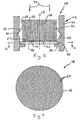
- Fig. 3 is a schematic cross-section representation of a catalytic reactor, in accordance with the present invention.
- Fig. 4 is a schematic end view of the honeycomb or open-cellular support retaining structure illustrated in Fig. 3.
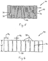
- Fig. 5 is a schematic representation of a portion of the catalytic reactor illustrated in Fig. 3, wherein the catalytic structure has thermally expanded in an outwardly radial direction towards the reaction chamber wall.
- Fig. 6 is a front elevational view of a strip which is used to form the flanges illustrated in Fig. 3.
- Figs. 7A through 7D depict partial sectional views of various configurations of the annular groove formed in the reaction chamber wall and used to retain the flanges.
- Fig. 8 is a schematic representation of a catalytic reactor, illustrating a different configuration of flanges.
- Fig. 9 is a front elevational view of a strip which is used to form the flanges illustrated in Fig. 8.
- Fig. 10 is a front elevational view of a pair of overlapping strips which can be used to form overlapping flanges.
- Figs. 11A through 11D depict partial sectional views of various profiles of flanges for use in the catalytic reactor of Fig. 8.
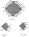
- Fig. 12 is a sectional view taken along lines 12-12 of Fig. 3, illustrating the radial centering assembly for the support retaining structure.
- Figs. 13 through 15 are sectional views depicting alternate embodiments of radially centering assemblies for both the support retaining structure and the catalyst structure.
- Fig. 16 is a perspective view of an outer band for framing a monolithic open cellular support retaining structure.
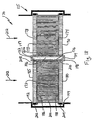
- Fig. 17 is a schematic representation of an alternate embodiment of a catalytic reactor having a center support member, in accordance with the present invention.
- Fig. 18 is a schematic representation of another alternate embodiment of a catalytic reactor having a center support member, in accordance with the present invention.
- a typical catalytic combustion reactor indicated generally at (10).
- the reactor includes a reaction chamber (12) which is downstream of a prebumer (14).
- the reactor further includes a compressor (16) which draws in air, pressurizes the air, and then delivers the pressurized air into the reaction chamber.
- the fuel which is introduced to the reaction chamber (12) via a fuel injector (18), and air are mixed and ignited, causing expansion thereof such that the hot gases leave the reaction chamber (12) and pass into to a drive turbine (20).
- a catalyst structure (22) is disposed within the reaction chamber (12).
- the catalyst structure (22) is positioned with its longitudinal passageways parallel to the flow of an oxygen-containing gas, such as air, and fuel mixture.
- the catalyst structure is positioned in this manner to obtain a uniform flow of air/fuel mixture through the catalyst structure.
- the mixture passes through longitudinal passageways or channels formed in the catalyst structure.
- multiple catalyst structures can be placed in series within the reaction chamber.
- outlet end refers to the downstream end of the component described where the partially or completely combusted air/fuel mixture exits the component.
- inlet end refers to the upstream end of the component described where the uncombusted air/fuel mixture is initially introduced to the component.
- the catalyst structure can be made according to any of the well-known designs, such as a monolithic catalyst structure comprising a multiplicity of parallel longitudinal channels or passageways at least partially coated with catalyst.
- Typical catalyst structures are disclosed in a variety of published references including U.S. Patent Nos. 5,183,401; 5,232,351; 5,248,251; 5,250,489 and 5,259,754 to Dalla Betta et al., as well as U.S. Patent No. 4,870,824 to Young et al.
- the catalyst structure may be fabricated from a metallic or ceramic substrate in the form of honeycombs, spiral rolls of corrugated sheet, columnar (or "handful of straws"), or other configurations having longitudinal channels or passageways permitting high gas space velocities with minimal pressure drops across the catalyst structure.
- a spiral catalyst structure such as that illustrated in Figs. 2A and 2B, may suitably be used.
- the catalyst structure (26) is fabricated by crimping a sheet of metal foil (28) into a corrugated or wavy pattern with depressions (30) and ridges (32).
- the corrugated sheet of metal foil is then rolled together with a flat metal sheet (34) to form a large spiral (36) of alternate layers of corrugated foil (28) and flat sheet (34) as a generally cylindrical unit.
- the depressions and the ridges of the foil cooperate with the sheet to form a multiplicity of longitudinal passageways or channels (37).
- the corrugated and/or the flat sheets are typically coated on one or both sides with a platinum group metal, preferably palladium and/or platinum, prior to being rolled together to form the spiral catalyst structure (26).
- While the illustrated catalyst structure (26) involves a metal foil corrugated in a straight channel structure combined with a flat foil
- other suitable spiral catalyst structures include those obtained when two or more corrugated foils having straight or herringbone corrugation patterns are wound together in non-nesting fashion.
- the catalyst support structure of the present invention is particularly useful in the case of metal spiral catalyst structures since they have a tendency to telescope or deform in the direction of gas flow when exposed to high gas flow rates at temperatures which are sufficiently high, e.g., 1,000°C or more, to soften or otherwise weaken the metal structure.
- the reactor includes a reaction chamber (42) defined by a generally cylindrical or tubular reaction chamber wall (44) defining a longitudinal axis X.
- a generally cylindrical monolithic open cellular or honeycomb-like support structure (48) is disposed in the reaction chamber for supporting a catalyst structure, such as the catalyst structure (26) illustrated in Fig. 2A.
- the catalyst structure (26) has an inlet end (50) and an outlet end (52).
- the support structure (48) has an inlet end (54) and an outlet end (56).
- the catalyst structure and the support structure are positioned within the reaction chamber so that the outlet end (52) of the catalyst structure abuts against the inlet end (54) of the support structure.
- the support structure is retained and secured in the reaction chamber by means of an annular lip or ridge (58) extending radially inwardly from the wall (44) of the reaction chamber.
- the annular ridge (58) forms a ledge on which the outside or peripheral edge of the support structure sits or rests, thereby limiting the movement of the support structure along the longitudinal axis. In this manner, any axial load placed on the support structure by the gas flow (46) through the catalyst structure is transferred from the support structure to the wall (44).
- the support structure is centered within the reaction chamber by a plurality of cooperating struts (60) and splines (62).
- the support structure (48) can be any suitable monolithic open cellular structure, such as that described in the co-pending application, U.S. Serial No. 08/462,639, entitled "Improved Support Structure For A Catalyst".
- the support structure can be constructed or fabricated by any conventional technique for forming monolithic honeycomb-like structures or cells, made up of strips or ribs of ceramic or metallic material bonded together to form a unitary structure.
- the support structure can be cast as a single unit in the appropriate mold, or the structure can be formed by bonding together a series of strips or ribs which have been previously molded or bent to afford the desired cellular opening configuration when they are bonded together. As shown in Fig.
- the support structure (48) has a multiplicity of cellular openings or passageways (64) extending in an axial direction parallel to the gas flow (46).
- the cellular openings are shown as being hexagonal in shape, the openings can have any suitable shape, such as circular, triangular, or trapezoidal.
- the support structure can include a circular outer band (66) which frames the peripheral surface of the support structure.
- the cross-sectional area of the catalyst structure (26), as taken in a direction perpendicular to longitudinal axis of the reactor, is sized to be less than the cross sectional area of the reaction chamber wall (44) such that a gap or an annular space (68) exists therebetween.
- This annular space is sized to accommodate the thermal expansion of the catalyst structure (26) and the support structure (48) which occurs on contact with the high temperature gas flow.
- the catalyst structure is positioned coaxially within the reaction chamber by a plurality of flexible flanges (70).
- the flanges extend from an annular groove (72) formed in the inner surface of the reaction chamber wall (44) to the outer peripheral surface of the catalyst structure.
- the plurality of flanges overlap one another and extend around the entire circumference of the catalyst structure to substantially block the flow of gas which would otherwise by-pass the catalyst structure through the annular space.
- the flanges (70) are sufficiently flexible so the flanges will bend as the catalyst structure thermally expands, as illustrated in Fig. 5, without placing enough stress on the catalyst structure to cause localized deformation of the catalyst structure at the points where the flanges contact the outer wall of the catalyst structure.
- the flanges can be made of any suitable flexible material having a relatively high elasticity, such as spring steel alloys, iron base alloys, stainless steels, cobalt and nickel based alloys, and pure metals such as aluminum or nickel.
- an oxidation resistant alloy such as an FeCrAl alloy, may be desirable.
- the flanges can be coated with aluminum to provide high temperature oxidation resistance.
- the plurality of flanges (70) radially center the generally cylindrical catalyst structure with respect to the cylindrical reaction chamber wall so they generally share a common axis. If the support structure is also radially centered, both the catalyst structure and the support structure will thermally expand in a radially outwardly direction from their respective centers. This simultaneous radial thermal expansion helps reduce the amount of lateral movement between the outlet end (52) of the catalyst structure (26) and the inlet end (54) of the support structure (48), thereby reducing the scraping or frictional relative movement therebetween. This helps prevent damage to the catalyst foils of the catalyst structure.
- the plurality of flanges can be separate components or can be formed from a single strip (74,) such as shown in Fig. 6.
- the strip has a plurality of slots (76) formed therethrough, thereby forming a plurality of tabs (78) which function as the flanges (70).
- the slots extend just short of the entire width of the strip, such that the strip has an intact edge (80).
- the strip (74) is positioned within the combustion chamber so that the intact edge (80) is attached to the outer peripheral surface of the catalyst structure. Once installed, the strip is formed into a conical shape so that the diameter of the intact edge is smaller than the diameter formed by the ends of the tabs.
- the strip (74) has a width W, which corresponds to the length of the flanges (70).
- the width W of the strip (74) is sized to accommodate the diameter of the catalyst structure relative to the diameter of the reaction chamber.
- the width W should be large enough to provide relatively large radial movement of the tabs (78) to maintain contact with the catalyst structure.
- the width W of the strip is suitably within the range of from about 25 mm to about 101 mm (about 1 inch to about 4 inches), and preferably within the range of from about 38mm to about 101 mm (about 1.5 inches to about 4 inches).
- the tabs have a width W t which is preferably sized so as to maintain a good sealing contact with the catalyst structure.
- the width W t of tabs is preferably relatively short so that the flat edge of the tab contacting the curvature of the outer diameter of the catalyst structure provides a generally tight seal.
- the width W t of the tabs can be larger since the outer diameter of the catalyst structure has less of a curvature.
- the width W t of the tabs is preferably within the range of from about 2.54 mm to about 7.62 mm (about 0.1 inches to about 0.3 inches).
- the width W t of the tabs is preferably within the range of from about 6.35 m to about 25.4 mm (about 0.25 inches to about 1.0 inch).
- the slots (76) have a width W s which is preferably sized so as to be narrow enough to minimize the leakage of bypassing air between the slots.
- a preferred range for the width W s of the slots is within the range of from about 0.00254 mm to about 0.762 mm (about 0.0001 inches to about 0.030 inches), and more preferably within the range of from about 0.0254 to about 0.51 mm (about 0.001 inches to about 0.020 inches).
- the thickness of the strip and the tabs should be sufficiently thick so as to provide a reasonable sealing force against the outer diameter of the catalyst structure.
- the thickness of the strip should also be sufficiently thin so that the force will not cause localized deformation of the catalyst structure at the points where the flanges contact the outer wall of the catalyst structure, especially since the catalyst structure can be operating at high temperatures and may not have relatively high tensile strength.
- the annular groove (72) formed in the reaction chamber wall (44) can have any suitable cross-sectional shape which retains the end of the flange.
- a groove (82) is formed in the wall having a curvilinear shaped contact profile which contacts the face of the flange.
- the curvilinear shape helps to minimize the stress placed on the deformed flange during thermal expansion of the catalyst structure.
- Fig. 7B for flanges having a shorter length the arcuate length of the curvilinear shaped profile of a groove (84) can be shortened.
- the contact profile of the annular groove does not have to be curvilinear, but may be straight, such as the contact profiles of the grooves (86) and (88), as shown in Figs. 7C and 7D, respectively.
- the groove (86) positions the flange (70) at a more severe angle with respect to the outer surface of the catalyst structure than the groove (88) to accommodate a larger width of the annular space, for example.
- a catalyst structure (26) having a plurality of flanges (90) which are positioned about the outer surface of the catalyst structure.
- the flanges (90) provide the same functions as the flanges (70), e.g., accommodating the thermal expansion of the catalyst structure, radially centering the catalyst structure with respect to the reaction chamber wall, and providing a sufficient seal for the annular space between the inner surface of the reaction chamber wall (44) and the outer peripheral surface of the catalyst structure.
- the flanges (90) can be formed from a strip (92), similar to the strip (74) of Fig. 6.
- the strip has a plurality of slots (94) formed therethrough, thereby forming a plurality of tabs (96) which function as the flanges (90).
- An unslotted portion (98) is wrapped around the periphery of the catalyst structure and preferably fastened thereto.
- the strip can be fastened by any suitable method, such as by bonding or spot welding the unslotted portion to the outer periphery of the catalyst structure.
- the strip (92) does not necessarily have to be fastened to the catalyst structure.
- the edge of the unslotted portion can be positioned adjacent the outlet end of the catalyst structure so that the support structure supports the strip (92).
- the tabs (96) are deformed outwardly to engage the inner wall of the reaction chamber. Since the tabs are deformed outwardly, the slots are opened creating a slight gap therebetween.
- a pair of overlapping strips (92a) and (92b) can be used, as shown in Fig. 10. The overlapping strips are positioned so that tabs of one strip are laid across the slots of the other strip.
- the tabs (96) can be bent to any suitable shape which provides a good seal between the catalyst structure and the support structure.
- Figs. 11A through 11D illustrate different suitable shapes for the tabs (96).
- Figs. 11A and 11B show tabs (100) and (102) having bent portions (100a) and (102a) and straight portions (100b) and (102b), respectively.
- the straight portions (100b) and (102b) end at edges (100c) and (102c), respectively, which contact the inner wall of the reaction chamber at a sharp line contact.
- a tab (104) has an axially extending portion (104a) which has a larger contact surface area for possible improved sealing.
- axially extending portion (104a) is less likely to bind on the reaction chamber wall than the sharp edges (100c) and (102c) of the tabs (100) and (102) when the catalyst structure thermally expands in the inlet direction.
- a tab (106) has a generally rounded portion providing a larger contact area and having even a lessor chance of binding than the tab (104) of Fig. 11C.
- flanges (70) and (90) have been described as being used in cooperation with the catalyst structure, flanges can also be used in cooperation with the support structure.
- struts (60) are fastened to inner surface of the reaction chamber wall.
- the splines (62) are fastened to support structure (48), and are preferably attached to the circular band (66) which frames the peripheral surface of the support structure.
- Each spline (62) has a radially extending groove (108) formed therein for receiving the associated strut.
- the radial height of the grooves and the struts is sized to allow for thermal expansion of the support structure relative to the thermal expansion of the reaction chamber wall.
- a gap exists between the bottom of the grooves and the edge of the strut, as shown in Fig. 12.
- the splines and struts cooperate to radially center the support structure within the reaction chamber wall to define an annular space (110) between the outer periphery of the support structure and the inner surface of the reaction chamber wall.
- the width of the annular space (110) is substantially the same around the entire periphery of the support structure. For example, when viewing Fig.
- the upper and lower struts and splines generally prevent the support structure from moving in a leftward or rightward direction.
- the left-hand and right-hand struts and splines generally prevent the support structure from moving in an upward or downward direction.
- the struts and splines prevent the support structure from rotating in a circumferential direction but allow the support structure to thermally expand radially outwardly so that as the support structure expands, the struts advance further into the grooves of the splines. It is advantageous to radially center the support structure, as well as the catalyst structure, to help reduce the amount of relative lateral movement between the outlet end of the catalyst structure and the inlet end of the support structure to reduce the scraping therebetween which can damage the catalyst foils.
- the embodiment of the support structure illustrated in Fig. 12 has four cooperating struts and splines, it should be understood that any number of struts and splines greater than one can be used.
- the cooperating struts and splines are equally spaced about the perimeter of the support structure.
- the struts and splines can be reversed, with the struts (60) fastened to the support structure (48), and the splines (62) fastened to the reaction chamber wall (44), as shown in Fig. 13.
- the arrangement of the struts and splines may also be alternated so that adjacent cooperating struts and splines have a reversed orientation.
- FIG. 14 there is shown an alternate embodiment of a radial centering assembly for the support structure (48) and the reaction chamber wall (44).
- a stud or pin (112) extends outwardly from the support structure and is slidably disposed within a slot (114) formed in the reaction chamber wall. The pin and the slot cooperate in a similar manner as the struts (60) and the splines (62), as described above and are considered to be equivalents thereof.
- Yet another embodiment of a radial centering assembly is illustrated in Fig. 15.
- a stud or pin (116) extends radially inwardly from the reaction chamber wall and is slidably disposed within a slot (118) formed in the support structure. If the catalyst structure were ceramic, for example, the slot (118) could be cut into the ceramic catalyst structure.
- the support structure may be desirable for the support structure to have a circular outer band having a thickness which is greater than the walls of the cells of the open cellular monolithic support structure.
- the outer band can be made of any suitable material, such as metal.
- the thicker metal band would provide strength for attachment points, such as for the struts or splines described above.
- the thicker metal band would also provide strength in the axial direction for multiple catalyst structures.
- the metal band has a larger thickness than the cell walls of the support structure, the cell walls would thermally expand at a greater rate than the band.
- the outer band may have a plurality of slots formed therein to allow the outer band to flex.
- the slots (122) can be formed in an alternating pattern spaced around the circumference of the outer band such that adjacent slots are formed through opposite edges, as shown in Fig. 16.
- the outer band should have sufficient flexibility to absorb the thermal expansion of the cell walls of the support structure without causing the cell walls to deform, yet strong enough to provide rigidity to the support structure.
- the slots are sized so as to minimize gas flow leakage therethrough.
- the width of the slots is suitably within a range of from about 0.0254 mm to about 1.27 mm (about 0.001 inches to about 0.050 inches), and preferably within a range of from about 0.05 mm to about 0.51 mm (about 0.002 inches to about 0.020 inches).
- the slots are spaced apart from one another to provide enough relaxation while maintaining the integrity of the outer band.
- the arc length between the slots is suitably within the range of from about 12.7 mm to about 15.2 cm (about 0.5 inches to about 6 inches), and preferably within the range of from about 2.54 to 7.62 cm (1 to 3 inches).
- outer band (120) was described in cooperation with the support structure, an outer band having similar features as the outer band (120) can be used with catalyst structure of the present invention.
- the reactor includes a reaction chamber (132) defined by a generally cylindrical reaction chamber wall (134).
- the reactor further includes a catalyst structure (138), which can be similar to the catalyst structure (26) of Fig. 3.
- the catalyst structure (138) has an inlet end (140) and an outlet end (142).
- the catalyst structure has an axial bore (143) formed therethrough which extends between the inlet and outlet ends.
- the catalyst structure is retained in the chamber by inlet and outlet monolithic open cellular support structures (144) and (146).
- the support structures (144) and (146) can be similar to the support structure (48) of Fig. 3.
- the inlet and outlet support structures (144) and (146) have axial bores (148) and (150), respectively, formed therethrough.
- the inlet support structure (144) has an inlet end (152) and an outlet end (154).
- the outlet support structure (146) has an inlet end (156) and an outlet end (158).
- the inlet and outlet support structures (144) and (146) are retained in the reaction chamber by abutting against inwardly extending annular ridges (160) and (162), respectively, extending radially inwardly from the wall (134) of the reaction chamber.
- a center support member (164) is disposed within the axial bores of the catalyst structure and the inlet and outlet support structures.
- the center support member (164) has radially outwardly extending flanges (166) and (168) formed on the ends thereof.
- the flange (166) abuts against the face of the inlet end of the inlet support structure.
- the flange (168) abuts against the face of the outlet end of the outlet support structure.
- the primary function of the center support member (164) is to transfer a portion of the force or axial load acting on the outlet support structure to the inlet support structure. More specifically, the flow of gas (136) exerts an axial load on the outlet support structure. Since the outlet support structure is supported about its perimeter by the ridge (162), the center portion of the outlet support structure is biased outward by this axial force. The force acting on the center of the outlet support structure is transferred to the center support member (164) via the flange (168). The force acting on the center support member is transferred to the center portion of the inlet support structure via the flange (166). Note that the forces acting on the perimeter of the inlet support structure are transferred to the reaction chamber wall via the ridge (160). The inlet support structure, therefore, assists in supporting the outlet support structure by means of the center support member.
- the outlet support structure is typically carrying a heavier load than the inlet support structure since the outlet support structure is positioned in an area of the combustion chamber having higher velocity gas flow and a larger pressure drop.
- the outlet support member is positioned in an area of the combustion chamber having a higher temperature, and thus the outlet support structure will have less strength than the inlet support structure.
- the support structure supports the catalyst support member. The advantage of having the center support member is that the outlet support structure is supported at the center instead of just its perimeter portion, thereby improving the structural integrity of the outlet support structure.
- a catalytic combustion reactor indicated generally at (170), which is similar to the reactor (130) of Fig. 17.
- the reactor (170) has a catalyst structure (172) having an inlet end (173) and an outlet end (174).
- the catalyst structure (172) is disposed within a cylindrical wall of a reaction chamber (175).
- the catalyst structure also has an axial bore (176) formed therethrough which extends between the inlet and outlet ends.
- the catalyst structure is retained in the chamber by inlet and outlet monolithic open cellular support structures (178) and (180).
- the inlet and outlet support structures (178) and (180) have axial bores (182) and (184), respectively, formed therethrough.
- the inlet support structure (178) has an inlet end (185) and an outlet end (186).
- the outlet support structure (180) has an inlet end (188) and an outlet end (190).
- the inlet and outlet support structures (178) and (180) are retained in the reaction chamber by abutting against inwardly extending shoulders (192) and (194), respectively, extending radially inwardly from the wall of the reaction chamber.
- the catalyst support structure and the inlet and outlet support structures are sandwiched between the shoulders (192) and (194) such that the catalyst structure is positioned between the inlet and outlet support structures.
- a center support member (196) is disposed within the axial bores of the catalyst structure and the inlet and outlet support structures.
- the center support member (196) has radially outwardly extending flanges (197) and (198) formed on the ends thereof.
- the flange (197) abuts against the face of the inlet end of the inlet support structure.
- the flange (198) abuts against the face of the outlet end of the outlet support structure.
- the catalyst support structure and the inlet and outlet support structures may have thick walled metal outer metal rings or bands (200), (202), and (204), respectively, formed thereabout to provide additional strength at the perimeters thereof
- the catalyst support structure and the inlet and outlet support structures may also have thick walled tubes (206), (208), and (210) which line the axial bores (176), (182), and (184), respectively, to provide additional strength at these regions.
- This configuration of the catalytic combustion reactor (170) provides support for any reverse flow load, in the direction opposite the normal flow of gas (212), which may occur in the reaction chamber.
- the gas flow load will force the catalyst structure and the inlet and outlet structures against the shoulder ( 192).
- the various support members of the present invention can be used in a process for the catalytic combustion of a hydrocarbonaceous or other combustible fuel, e.g., methane, ethane, H 2 or CO/H 2 mixtures.
- a hydrocarbonaceous or other combustible fuel e.g., methane, ethane, H 2 or CO/H 2 mixtures.
- an oxygen-containing gas such as air
- This oxygen/fuel mixture is passed as a flowing gas through a monolithic catalyst structure that is positioned within a reaction chamber to combust the oxygen/fuel mixture and form a hot, partially or completely combusted, gas product.
- a variety of catalyst structures can be used in this process.
- a catalyst having integral heat exchange surfaces as described in U.S. Patent No. 5,230,489 entitled “Catalyst Structure Having Integral Heat Exchange”, or a graded palladium-containing partial combustion process catalyst as described in U.S. Patent Nos. 5,248,251 and 5,258,349 both entitled “Graded Palladium-Containing Partial Combustion Catalyst And Process For Using It", may be used in this invention.
- the process may involve complete combustion of the fuel or partial combustion of the fuel as described in the co-pending application, U.S. Serial No. 08/088,614, entitled “Process For Burning Combustible Mixtures”.
- the process may be a multi-stage process in which the fuel is combusted stepwise using specific catalysts and catalyst structures in the various stages, as described in U.S. Patent No. 5,232,357, entitled ''Multistage Process For Combusting Fuel Mixtures Using Oxide Catalyst In The Hot Stage".
- the catalyst structure can be made up of a multiplicity of longitudinally disposed channels, wherein the channel walls are formed by a thin metal substrate which expands on exposure to the heat generated in the high temperature reaction.
- the channels have inlet and outlet ends for passage of a flowing reaction gas mixture.
- the support structure can be comprised of cells having walls formed by strips of high temperature resistant metal or ceramic material. The cellular openings are in fluid communication with the outlet ends of the channels in the catalyst structure.
- the support structure is positioned at the outlet end of the catalyst structure to abut against the outlet end of the catalyst structure so that the cross-section of the support structure essentially covers the end face of the catalyst structure.
- a second support structure can also be used which is positioned at the inlet end of the catalyst structure to abut against the inlet ends of the channels in the catalyst structure.
- the catalyst structure is sized such that it has a reduced cross-sectional area, taken in a direction perpendicular to its longitudinal axis, relative to the cross-sectional area of the reaction chamber-such that an annular space is formed between the outer periphery of the catalyst structure and the inner surface of the reaction chamber as defined by the reaction chamber wall.
- the annular space is sized to allow for thermal expansion of the catalyst structure which occurs during the high temperature reaction without causing the catalyst structure to be compressed and deformed by pressing against the reaction chamber wall.
- the flow of reaction gas mixture through the annular space is obstructed by inserting one or more flexible flanges which extend from the outer peripheral surface of the catalyst structure to the inner surface of the reaction chamber wall.
- the flanges substantially block the flow of reaction gas mixture which would otherwise by-pass the catalyst structure.
- the flanges are sufficiently flexible so that the flanges will bend as the catalyst structure undergoes thermal expansion without placing sufficient stress on the catalyst structure to cause localized deformation of the catalyst structure at the points of contact with the catalyst structural wall.
- the catalyst structure and the support structure are radially centered in a stable position within the reaction chamber such that the annular space between the outer periphery of the catalyst structure and the inner surface of the reaction chamber is substantially the same around the entire periphery of the catalyst structure.
- the catalyst structure and the support structure are radially centered by means of three or more mated radial splines and struts mounted on the peripheral surface of the open cellular support structure adjacent to the inner wall surface of the reaction chamber and/or on the peripheral surface of the catalyst structure with the corresponding mating spline or strut being mounted on the inner surface of the reaction chamber wall opposite from the spline or strut on the support structure and/or catalyst structure.
- the strut is meshed into the corresponding groove formed by the spline to hold the catalyst structure in place.
- the depth of the groove in the spline and/or height of the strut is sized to allow for thermal expansion of the open cellular support structure and/or the catalyst structure which occurs during the high temperature reaction, while maintaining the centered position of the catalyst structure within the reaction chamber.
- the support structure is stabilized against deformation caused by the axial load exerted on the face of the support structure in a direction parallel to the longitudinal axis of the catalyst structure during passage of the flowing reaction gas mixture by means of a center support member.
- the center support member is secured to, and extends from, the middle of the end face of the outlet side support structure through the center of the catalyst structure in a longitudinal direction to the middle of the end face of the inlet side support structure where it is also secured.
- the force exerted on the outlet side of the support structure by the flowing gas reaction gas mixture is transferred via the center support member to the inlet side support structure.
- Additional structure integrity is also provided to the open cellular support structure located at the inlet and the outlet ends of the catalyst structure by means of a solid, high temperature resistant outer band.
- the band is bonded to the peripheral surface of the open cellular support structure.
- the band is thicker in width than the strips of high temperature resistant metal or ceramic material making up the cell walls of the open cellular support structure.
- the band has slots cut in its outer peripheral portion to provide sufficient flexibility in the metal band to absorb the thermal expansion of the thinner open cellular structure which occurs during the high temperature reaction without causing the open cellular support structure to deform due to the difference in thermal expansion between the open cellular structure and the metal band bonded thereto.
Landscapes
- Chemical & Material Sciences (AREA)
- Engineering & Computer Science (AREA)
- Chemical Kinetics & Catalysis (AREA)
- Combustion & Propulsion (AREA)
- Mechanical Engineering (AREA)
- General Engineering & Computer Science (AREA)
- Health & Medical Sciences (AREA)
- Toxicology (AREA)
- Physical Or Chemical Processes And Apparatus (AREA)
- Catalysts (AREA)
- Exhaust Gas After Treatment (AREA)
- Devices And Processes Conducted In The Presence Of Fluids And Solid Particles (AREA)
Priority Applications (1)
| Application Number | Priority Date | Filing Date | Title |
|---|---|---|---|
| DK99922757T DK1075628T3 (da) | 1998-04-30 | 1999-04-29 | Støttestrukturer til en katalysator |
Applications Claiming Priority (3)
| Application Number | Priority Date | Filing Date | Title |
|---|---|---|---|
| US09/070,443 US6217832B1 (en) | 1998-04-30 | 1998-04-30 | Support structures for a catalyst |
| US70443 | 1998-04-30 | ||
| PCT/US1999/009469 WO1999056064A1 (en) | 1998-04-30 | 1999-04-29 | Support structures for a catalyst |
Publications (2)
| Publication Number | Publication Date |
|---|---|
| EP1075628A1 EP1075628A1 (en) | 2001-02-14 |
| EP1075628B1 true EP1075628B1 (en) | 2004-09-29 |
Family
ID=22095315
Family Applications (1)
| Application Number | Title | Priority Date | Filing Date |
|---|---|---|---|
| EP99922757A Expired - Lifetime EP1075628B1 (en) | 1998-04-30 | 1999-04-29 | Support structures for a catalyst |
Country Status (10)
| Country | Link |
|---|---|
| US (1) | US6217832B1 (https=) |
| EP (1) | EP1075628B1 (https=) |
| JP (1) | JP2002513132A (https=) |
| KR (1) | KR20010043137A (https=) |
| CN (1) | CN1299456A (https=) |
| AT (1) | ATE278158T1 (https=) |
| AU (1) | AU3968299A (https=) |
| DE (1) | DE69920682T2 (https=) |
| DK (1) | DK1075628T3 (https=) |
| WO (1) | WO1999056064A1 (https=) |
Cited By (1)
| Publication number | Priority date | Publication date | Assignee | Title |
|---|---|---|---|---|
| KR20190118170A (ko) * | 2017-02-27 | 2019-10-17 | 할도르 토프쉐 에이/에스 | 촉매 지지 시스템을 가진 화학 반응기 |
Families Citing this family (72)
| Publication number | Priority date | Publication date | Assignee | Title |
|---|---|---|---|---|
| JP2000297635A (ja) * | 1999-04-09 | 2000-10-24 | Yutaka Giken Co Ltd | 排気コンバータ |
| US6613296B1 (en) * | 2000-01-31 | 2003-09-02 | Delphi Technologies, Inc. | Relieved support material for catalytic converter and the process of making the same |
| US6649137B2 (en) * | 2000-05-23 | 2003-11-18 | Rohm And Haas Company | Apparatus with improved safety features for high temperature industrial processes |
| US7121097B2 (en) | 2001-01-16 | 2006-10-17 | Catalytica Energy Systems, Inc. | Control strategy for flexible catalytic combustion system |
| US6718772B2 (en) | 2000-10-27 | 2004-04-13 | Catalytica Energy Systems, Inc. | Method of thermal NOx reduction in catalytic combustion systems |
| TW534945B (en) * | 2000-11-13 | 2003-06-01 | Catalytica Energy Sys Inc | Thermally tolerant support structure for a catalytic combustion catalyst |
| US7182924B2 (en) * | 2001-03-13 | 2007-02-27 | Corning Incorporated | Substrate packing for monolith reactors |
| US6796129B2 (en) | 2001-08-29 | 2004-09-28 | Catalytica Energy Systems, Inc. | Design and control strategy for catalytic combustion system with a wide operating range |
| JP4294964B2 (ja) * | 2002-03-15 | 2009-07-15 | 日本碍子株式会社 | セラミックスハニカム構造体の製造方法 |
| US20030194363A1 (en) * | 2002-04-12 | 2003-10-16 | Koripella Chowdary Ramesh | Chemical reactor and fuel processor utilizing ceramic technology |
| US20030194359A1 (en) * | 2002-04-12 | 2003-10-16 | Gervasio Dominic Francis | Combustion heater and fuel processor utilizing ceramic technology |
| US7250151B2 (en) * | 2002-08-15 | 2007-07-31 | Velocys | Methods of conducting simultaneous endothermic and exothermic reactions |
| US7014835B2 (en) | 2002-08-15 | 2006-03-21 | Velocys, Inc. | Multi-stream microchannel device |
| US20040255588A1 (en) * | 2002-12-11 | 2004-12-23 | Kare Lundberg | Catalytic preburner and associated methods of operation |
| BRPI0406806A (pt) * | 2003-01-17 | 2005-12-27 | Catalytica Energy Sys Inc | Sistema e método de controle dinâmico para multicombustor catalìtico para motor de turbina a gás |
| US7220699B2 (en) * | 2003-03-31 | 2007-05-22 | Intelligent Energy, Inc. | Catalyst incorporation in a microreactor |
| WO2005026675A2 (en) * | 2003-09-05 | 2005-03-24 | Catalytica Energy Systems, Inc. | Catalyst module overheating detection and methods of response |
| US7691338B2 (en) * | 2004-03-10 | 2010-04-06 | Siemens Energy, Inc. | Two stage catalytic combustor |
| US7506516B2 (en) | 2004-08-13 | 2009-03-24 | Siemens Energy, Inc. | Concentric catalytic combustor |
| US7509807B2 (en) * | 2004-08-13 | 2009-03-31 | Siemens Energy, Inc. | Concentric catalytic combustor |
| US7655194B2 (en) * | 2005-01-18 | 2010-02-02 | Dcl International Inc. | Catalyst substrate support |
| GB0504622D0 (en) | 2005-03-05 | 2005-04-13 | Accentus Plc | Catalytic reactors |
| US7653998B1 (en) | 2005-09-14 | 2010-02-02 | Miratech Corporation | Wound process element and method of production |
| US20070239283A1 (en) * | 2006-04-11 | 2007-10-11 | Berger Richard A | Acetabular cup conversion ring |
| US8308811B2 (en) * | 2006-04-11 | 2012-11-13 | Zimmer, Inc. | Acetabular cup conversion ring |
| US8256221B2 (en) | 2007-04-05 | 2012-09-04 | Siemens Energy, Inc. | Concentric tube support assembly |
| US7919052B2 (en) * | 2007-07-27 | 2011-04-05 | Silex Innovations Inc. | Securing catalyst element in catalytic converter with bolted bar |
| US8393160B2 (en) | 2007-10-23 | 2013-03-12 | Flex Power Generation, Inc. | Managing leaks in a gas turbine system |
| US8671658B2 (en) | 2007-10-23 | 2014-03-18 | Ener-Core Power, Inc. | Oxidizing fuel |
| DE102008025593A1 (de) * | 2008-05-28 | 2009-12-03 | Emitec Gesellschaft Für Emissionstechnologie Mbh | Metallischer Wabenkörper mit definierten Verbindungsstellen |
| US8701413B2 (en) * | 2008-12-08 | 2014-04-22 | Ener-Core Power, Inc. | Oxidizing fuel in multiple operating modes |
| US8621869B2 (en) | 2009-05-01 | 2014-01-07 | Ener-Core Power, Inc. | Heating a reaction chamber |
| US20100275611A1 (en) * | 2009-05-01 | 2010-11-04 | Edan Prabhu | Distributing Fuel Flow in a Reaction Chamber |
| EP2547888A4 (en) | 2010-03-15 | 2016-03-16 | Ener Core Power Inc | TREATMENT OF FUEL AND WATER |
| US9057028B2 (en) | 2011-05-25 | 2015-06-16 | Ener-Core Power, Inc. | Gasifier power plant and management of wastes |
| US9273606B2 (en) | 2011-11-04 | 2016-03-01 | Ener-Core Power, Inc. | Controls for multi-combustor turbine |
| US9279364B2 (en) | 2011-11-04 | 2016-03-08 | Ener-Core Power, Inc. | Multi-combustor turbine |
| RU2014129646A (ru) * | 2011-12-27 | 2016-02-20 | Кавасаки Дзюкогё Кабусики Кайся | Каталитическая камера сгорания в газотурбинном двигателе |
| JPWO2013099583A1 (ja) * | 2011-12-27 | 2015-04-30 | 川崎重工業株式会社 | ガスタービンエンジンにおける触媒燃焼器 |
| US8844473B2 (en) | 2012-03-09 | 2014-09-30 | Ener-Core Power, Inc. | Gradual oxidation with reciprocating engine |
| US8980192B2 (en) | 2012-03-09 | 2015-03-17 | Ener-Core Power, Inc. | Gradual oxidation below flameout temperature |
| US9567903B2 (en) | 2012-03-09 | 2017-02-14 | Ener-Core Power, Inc. | Gradual oxidation with heat transfer |
| US9534780B2 (en) | 2012-03-09 | 2017-01-03 | Ener-Core Power, Inc. | Hybrid gradual oxidation |
| US9353946B2 (en) | 2012-03-09 | 2016-05-31 | Ener-Core Power, Inc. | Gradual oxidation with heat transfer |
| US8671917B2 (en) | 2012-03-09 | 2014-03-18 | Ener-Core Power, Inc. | Gradual oxidation with reciprocating engine |
| US9371993B2 (en) | 2012-03-09 | 2016-06-21 | Ener-Core Power, Inc. | Gradual oxidation below flameout temperature |
| US9381484B2 (en) | 2012-03-09 | 2016-07-05 | Ener-Core Power, Inc. | Gradual oxidation with adiabatic temperature above flameout temperature |
| US9359948B2 (en) | 2012-03-09 | 2016-06-07 | Ener-Core Power, Inc. | Gradual oxidation with heat control |
| US9017618B2 (en) | 2012-03-09 | 2015-04-28 | Ener-Core Power, Inc. | Gradual oxidation with heat exchange media |
| US9726374B2 (en) | 2012-03-09 | 2017-08-08 | Ener-Core Power, Inc. | Gradual oxidation with flue gas |
| US8980193B2 (en) | 2012-03-09 | 2015-03-17 | Ener-Core Power, Inc. | Gradual oxidation and multiple flow paths |
| US9359947B2 (en) | 2012-03-09 | 2016-06-07 | Ener-Core Power, Inc. | Gradual oxidation with heat control |
| US9328916B2 (en) | 2012-03-09 | 2016-05-03 | Ener-Core Power, Inc. | Gradual oxidation with heat control |
| US9206980B2 (en) | 2012-03-09 | 2015-12-08 | Ener-Core Power, Inc. | Gradual oxidation and autoignition temperature controls |
| US9273608B2 (en) | 2012-03-09 | 2016-03-01 | Ener-Core Power, Inc. | Gradual oxidation and autoignition temperature controls |
| US8807989B2 (en) | 2012-03-09 | 2014-08-19 | Ener-Core Power, Inc. | Staged gradual oxidation |
| US8926917B2 (en) | 2012-03-09 | 2015-01-06 | Ener-Core Power, Inc. | Gradual oxidation with adiabatic temperature above flameout temperature |
| US9347664B2 (en) | 2012-03-09 | 2016-05-24 | Ener-Core Power, Inc. | Gradual oxidation with heat control |
| US9234660B2 (en) | 2012-03-09 | 2016-01-12 | Ener-Core Power, Inc. | Gradual oxidation with heat transfer |
| US9267432B2 (en) | 2012-03-09 | 2016-02-23 | Ener-Core Power, Inc. | Staged gradual oxidation |
| US9328660B2 (en) | 2012-03-09 | 2016-05-03 | Ener-Core Power, Inc. | Gradual oxidation and multiple flow paths |
| JP5917311B2 (ja) * | 2012-06-19 | 2016-05-11 | 株式会社東芝 | 軸流タービン |
| WO2014166621A1 (de) * | 2013-04-08 | 2014-10-16 | Oerlikon Trading Ag, Trübbach | Zentrierung einer platte in einer halterung sowohl bei raum- als auch bei höheren temperaturen |
| CN104941536B (zh) * | 2014-03-31 | 2020-12-25 | 英尼奥斯欧洲股份公司 | 用于氧化反应器的空气格栅系统和适应其中的挠曲的方法 |
| JP6404078B2 (ja) | 2014-10-15 | 2018-10-10 | 三菱重工業株式会社 | 燃料供給システム、ジェットエンジン、及び、燃料供給システムの製造方法 |
| CN108104921B (zh) * | 2016-01-06 | 2020-04-03 | 吴宝昕 | 抗老化催化器 |
| JP6699187B2 (ja) * | 2016-01-18 | 2020-05-27 | 富士通株式会社 | 排気浄化装置 |
| US20210220813A1 (en) * | 2020-01-16 | 2021-07-22 | Johnson Matthey Public Limited Company | Pallet for supporting a catalyst monolith during coating |
| US11433367B2 (en) * | 2020-01-21 | 2022-09-06 | Zoneflow Reactor Technologies, LLC | Support structure for structured catalyst packings |
| JP7407635B2 (ja) * | 2020-03-26 | 2024-01-04 | 大阪瓦斯株式会社 | 反応装置 |
| US20250281893A1 (en) * | 2024-03-08 | 2025-09-11 | Kellogg Brown & Root Llc | Floating support grid system for horizontal ammonia converter basket catalyst bed |
| CN119455660A (zh) * | 2025-01-10 | 2025-02-18 | 浙江环耀环境建设有限公司 | 一种抗堵塞co催化氧化模块及制备工艺 |
Family Cites Families (23)
| Publication number | Priority date | Publication date | Assignee | Title |
|---|---|---|---|---|
| US3156094A (en) * | 1962-11-21 | 1964-11-10 | Gen Electric | Catalytic ignition means for a jet engine thrust augmentation system |
| DE2313156A1 (de) * | 1973-03-16 | 1974-09-19 | Degussa | Abgasreinigungsvorrichtung |
| US4413470A (en) * | 1981-03-05 | 1983-11-08 | Electric Power Research Institute, Inc. | Catalytic combustion system for a stationary combustion turbine having a transition duct mounted catalytic element |
| JPS5941621A (ja) * | 1982-08-31 | 1984-03-07 | Toyota Motor Corp | モノリス触媒コンバ−タ |
| JPS59142332A (ja) * | 1983-02-01 | 1984-08-15 | Mitsubishi Heavy Ind Ltd | ガスタ−ビン用燃焼器 |
| US4870824A (en) | 1987-08-24 | 1989-10-03 | Westinghouse Electric Corp. | Passively cooled catalytic combustor for a stationary combustion turbine |
| JPS6483812A (en) * | 1987-09-25 | 1989-03-29 | Toshiba Corp | Supporting structure for ceramic honeycomb |
| JPH01121505A (ja) * | 1987-11-06 | 1989-05-15 | Toshiba Corp | セラミックハニカムの支持構造 |
| JPH01147109A (ja) * | 1987-11-30 | 1989-06-08 | Calsonic Corp | 触媒コンバータ |
| DE3926072C2 (de) * | 1989-08-07 | 1994-01-13 | Emitec Emissionstechnologie | Katalysator zur Abgasreinigung mit elastischen Elementen zum Ausgleich von Längsdehnungen |
| US5140813A (en) * | 1990-10-31 | 1992-08-25 | Whittenberger William A | Composite catalytic converter |
| US5259754A (en) | 1990-11-26 | 1993-11-09 | Catalytica, Inc. | Partial combustion catalyst of palladium on a zirconia support and a process for using it |
| US5183401A (en) | 1990-11-26 | 1993-02-02 | Catalytica, Inc. | Two stage process for combusting fuel mixtures |
| US5248251A (en) | 1990-11-26 | 1993-09-28 | Catalytica, Inc. | Graded palladium-containing partial combustion catalyst and a process for using it |
| US5232357A (en) | 1990-11-26 | 1993-08-03 | Catalytica, Inc. | Multistage process for combusting fuel mixtures using oxide catalysts in the hot stage |
| US5250489A (en) | 1990-11-26 | 1993-10-05 | Catalytica, Inc. | Catalyst structure having integral heat exchange |
| US5232351A (en) | 1992-07-13 | 1993-08-03 | Tecumseh Products Company | Centrifugal oil pump booster |
| US5461864A (en) | 1993-12-10 | 1995-10-31 | Catalytica, Inc. | Cooled support structure for a catalyst |
| DE19508217A1 (de) * | 1995-03-08 | 1996-09-12 | Emitec Emissionstechnologie | Metallischer Wabenkörper |
| EP1009955A1 (en) * | 1996-06-10 | 2000-06-21 | Catalytica, Inc. | Support structure for a catalyst |
| US6017498A (en) * | 1998-01-14 | 2000-01-25 | Metex Mfg. Corporation | Catalytic converter support device |
| US6691678B1 (en) | 2000-04-05 | 2004-02-17 | Hitachi, Ltd. | Throttle assembly for internal combustion engine, and throttle sensor |
| DE112010001932B4 (de) | 2009-06-19 | 2018-08-02 | Murata Manufacturing Co., Ltd. | Hochfrequenzmodul |
-
1998
- 1998-04-30 US US09/070,443 patent/US6217832B1/en not_active Expired - Fee Related
-
1999
- 1999-04-29 CN CN99805633A patent/CN1299456A/zh active Pending
- 1999-04-29 EP EP99922757A patent/EP1075628B1/en not_active Expired - Lifetime
- 1999-04-29 JP JP2000546182A patent/JP2002513132A/ja not_active Withdrawn
- 1999-04-29 WO PCT/US1999/009469 patent/WO1999056064A1/en not_active Ceased
- 1999-04-29 AU AU39682/99A patent/AU3968299A/en not_active Abandoned
- 1999-04-29 DE DE69920682T patent/DE69920682T2/de not_active Expired - Fee Related
- 1999-04-29 AT AT99922757T patent/ATE278158T1/de not_active IP Right Cessation
- 1999-04-29 DK DK99922757T patent/DK1075628T3/da active
- 1999-04-29 KR KR1020007012031A patent/KR20010043137A/ko not_active Withdrawn
Cited By (1)
| Publication number | Priority date | Publication date | Assignee | Title |
|---|---|---|---|---|
| KR20190118170A (ko) * | 2017-02-27 | 2019-10-17 | 할도르 토프쉐 에이/에스 | 촉매 지지 시스템을 가진 화학 반응기 |
Also Published As
| Publication number | Publication date |
|---|---|
| DE69920682D1 (de) | 2004-11-04 |
| WO1999056064A1 (en) | 1999-11-04 |
| CN1299456A (zh) | 2001-06-13 |
| DE69920682T2 (de) | 2006-02-23 |
| EP1075628A1 (en) | 2001-02-14 |
| AU3968299A (en) | 1999-11-16 |
| JP2002513132A (ja) | 2002-05-08 |
| US6217832B1 (en) | 2001-04-17 |
| KR20010043137A (ko) | 2001-05-25 |
| DK1075628T3 (da) | 2005-01-17 |
| ATE278158T1 (de) | 2004-10-15 |
Similar Documents
| Publication | Publication Date | Title |
|---|---|---|
| EP1075628B1 (en) | Support structures for a catalyst | |
| US6116014A (en) | Support structure for a catalyst in a combustion reaction chamber | |
| US5461864A (en) | Cooled support structure for a catalyst | |
| JP4256709B2 (ja) | ガスタービンエンジンの燃焼器用の環状一体形の波形ライナ | |
| CN101318149B (zh) | 带缺口卸荷的微结构 | |
| EP1205712B1 (en) | Catalytic combustor flow conditioner for providing a uniform gas velocity distribution | |
| CN1147287A (zh) | 利用整体换热的改进型催化剂结构件 | |
| US6829896B2 (en) | Catalytic oxidation module for a gas turbine engine | |
| JPH04103818A (ja) | 排気ガス浄化装置 | |
| US7506516B2 (en) | Concentric catalytic combustor | |
| US7594400B2 (en) | Catalytic oxidation module for a gas turbine engine | |
| JP3909435B2 (ja) | 触媒式燃焼器のための熱許容支持構造 | |
| US20040005250A1 (en) | Exhaust-gas catalytic converter and catalytic converter body, preferably for the purification of exhaust gases from internal combustion engines | |
| WO2002092212A2 (en) | Conduit positioner | |
| CN1147288A (zh) | 任选带有下游稳焰器的利用整体换热的改进型方法和催化剂结构件 | |
| CA2257874A1 (en) | Support structure for a catalyst | |
| JP2002512673A (ja) | 触媒用支持構造 | |
| KR20000016529A (ko) | 촉매용 지지구조물 | |
| CN1228152A (zh) | 催化剂用的支承结构 | |
| RU2160415C2 (ru) | Опорная конструкция(варианты) для крепления в реакционной камере каталитической структуры, способ крепления этой структуры в камере и способ каталитического сгорания топлива | |
| US8307653B2 (en) | Combined catalysts for the combustion of fuel in gas turbines | |
| US7509807B2 (en) | Concentric catalytic combustor | |
| JPH07290617A (ja) | 触媒用金属担体 | |
| JPS63290305A (ja) | 接触燃焼装置 |
Legal Events
| Date | Code | Title | Description |
|---|---|---|---|
| PUAI | Public reference made under article 153(3) epc to a published international application that has entered the european phase |
Free format text: ORIGINAL CODE: 0009012 |
|
| 17P | Request for examination filed |
Effective date: 20001107 |
|
| AK | Designated contracting states |
Kind code of ref document: A1 Designated state(s): AT BE CH CY DE DK ES FI FR GB GR IE IT LI LU MC NL PT SE |
|
| 17Q | First examination report despatched |
Effective date: 20021203 |
|
| GRAP | Despatch of communication of intention to grant a patent |
Free format text: ORIGINAL CODE: EPIDOSNIGR1 |
|
| GRAS | Grant fee paid |
Free format text: ORIGINAL CODE: EPIDOSNIGR3 |
|
| GRAA | (expected) grant |
Free format text: ORIGINAL CODE: 0009210 |
|
| AK | Designated contracting states |
Kind code of ref document: B1 Designated state(s): AT BE CH CY DE DK ES FI FR GB GR IE IT LI LU MC NL PT SE |
|
| PG25 | Lapsed in a contracting state [announced via postgrant information from national office to epo] |
Ref country code: NL Free format text: LAPSE BECAUSE OF FAILURE TO SUBMIT A TRANSLATION OF THE DESCRIPTION OR TO PAY THE FEE WITHIN THE PRESCRIBED TIME-LIMIT Effective date: 20040929 Ref country code: LI Free format text: LAPSE BECAUSE OF FAILURE TO SUBMIT A TRANSLATION OF THE DESCRIPTION OR TO PAY THE FEE WITHIN THE PRESCRIBED TIME-LIMIT Effective date: 20040929 Ref country code: IT Free format text: LAPSE BECAUSE OF FAILURE TO SUBMIT A TRANSLATION OF THE DESCRIPTION OR TO PAY THE FEE WITHIN THE PRESCRIBED TIME-LIMIT;WARNING: LAPSES OF ITALIAN PATENTS WITH EFFECTIVE DATE BEFORE 2007 MAY HAVE OCCURRED AT ANY TIME BEFORE 2007. THE CORRECT EFFECTIVE DATE MAY BE DIFFERENT FROM THE ONE RECORDED. Effective date: 20040929 Ref country code: FI Free format text: LAPSE BECAUSE OF FAILURE TO SUBMIT A TRANSLATION OF THE DESCRIPTION OR TO PAY THE FEE WITHIN THE PRESCRIBED TIME-LIMIT Effective date: 20040929 Ref country code: CH Free format text: LAPSE BECAUSE OF FAILURE TO SUBMIT A TRANSLATION OF THE DESCRIPTION OR TO PAY THE FEE WITHIN THE PRESCRIBED TIME-LIMIT Effective date: 20040929 Ref country code: BE Free format text: LAPSE BECAUSE OF FAILURE TO SUBMIT A TRANSLATION OF THE DESCRIPTION OR TO PAY THE FEE WITHIN THE PRESCRIBED TIME-LIMIT Effective date: 20040929 Ref country code: AT Free format text: LAPSE BECAUSE OF FAILURE TO SUBMIT A TRANSLATION OF THE DESCRIPTION OR TO PAY THE FEE WITHIN THE PRESCRIBED TIME-LIMIT Effective date: 20040929 |
|
| REG | Reference to a national code |
Ref country code: GB Ref legal event code: FG4D |
|
| REG | Reference to a national code |
Ref country code: CH Ref legal event code: EP |
|
| REG | Reference to a national code |
Ref country code: IE Ref legal event code: FG4D |
|
| REF | Corresponds to: |
Ref document number: 69920682 Country of ref document: DE Date of ref document: 20041104 Kind code of ref document: P |
|
| PG25 | Lapsed in a contracting state [announced via postgrant information from national office to epo] |
Ref country code: SE Free format text: LAPSE BECAUSE OF FAILURE TO SUBMIT A TRANSLATION OF THE DESCRIPTION OR TO PAY THE FEE WITHIN THE PRESCRIBED TIME-LIMIT Effective date: 20041229 Ref country code: GR Free format text: LAPSE BECAUSE OF FAILURE TO SUBMIT A TRANSLATION OF THE DESCRIPTION OR TO PAY THE FEE WITHIN THE PRESCRIBED TIME-LIMIT Effective date: 20041229 |
|
| PG25 | Lapsed in a contracting state [announced via postgrant information from national office to epo] |
Ref country code: ES Free format text: LAPSE BECAUSE OF FAILURE TO SUBMIT A TRANSLATION OF THE DESCRIPTION OR TO PAY THE FEE WITHIN THE PRESCRIBED TIME-LIMIT Effective date: 20050109 |
|
| REG | Reference to a national code |
Ref country code: DK Ref legal event code: T3 |
|
| NLV1 | Nl: lapsed or annulled due to failure to fulfill the requirements of art. 29p and 29m of the patents act | ||
| REG | Reference to a national code |
Ref country code: CH Ref legal event code: PL |
|
| PG25 | Lapsed in a contracting state [announced via postgrant information from national office to epo] |
Ref country code: LU Free format text: LAPSE BECAUSE OF NON-PAYMENT OF DUE FEES Effective date: 20050429 Ref country code: IE Free format text: LAPSE BECAUSE OF NON-PAYMENT OF DUE FEES Effective date: 20050429 Ref country code: CY Free format text: LAPSE BECAUSE OF FAILURE TO SUBMIT A TRANSLATION OF THE DESCRIPTION OR TO PAY THE FEE WITHIN THE PRESCRIBED TIME-LIMIT Effective date: 20050429 |
|
| PG25 | Lapsed in a contracting state [announced via postgrant information from national office to epo] |
Ref country code: MC Free format text: LAPSE BECAUSE OF NON-PAYMENT OF DUE FEES Effective date: 20050430 |
|
| PG25 | Lapsed in a contracting state [announced via postgrant information from national office to epo] |
Ref country code: DK Free format text: LAPSE BECAUSE OF NON-PAYMENT OF DUE FEES Effective date: 20050502 |
|
| PLBE | No opposition filed within time limit |
Free format text: ORIGINAL CODE: 0009261 |
|
| STAA | Information on the status of an ep patent application or granted ep patent |
Free format text: STATUS: NO OPPOSITION FILED WITHIN TIME LIMIT |
|
| ET | Fr: translation filed | ||
| 26N | No opposition filed |
Effective date: 20050630 |
|
| REG | Reference to a national code |
Ref country code: DK Ref legal event code: EBP |
|
| REG | Reference to a national code |
Ref country code: FR Ref legal event code: CD Ref country code: FR Ref legal event code: CA |
|
| REG | Reference to a national code |
Ref country code: FR Ref legal event code: RM |
|
| REG | Reference to a national code |
Ref country code: GB Ref legal event code: 732E |
|
| PGFP | Annual fee paid to national office [announced via postgrant information from national office to epo] |
Ref country code: DE Payment date: 20070430 Year of fee payment: 9 |
|
| REG | Reference to a national code |
Ref country code: FR Ref legal event code: TP |
|
| GBPC | Gb: european patent ceased through non-payment of renewal fee |
Effective date: 20070429 |
|
| PG25 | Lapsed in a contracting state [announced via postgrant information from national office to epo] |
Ref country code: PT Free format text: LAPSE BECAUSE OF NON-PAYMENT OF DUE FEES Effective date: 20050228 |
|
| PG25 | Lapsed in a contracting state [announced via postgrant information from national office to epo] |
Ref country code: GB Free format text: LAPSE BECAUSE OF NON-PAYMENT OF DUE FEES Effective date: 20070429 |
|
| PGFP | Annual fee paid to national office [announced via postgrant information from national office to epo] |
Ref country code: FR Payment date: 20070503 Year of fee payment: 9 |
|
| PGFP | Annual fee paid to national office [announced via postgrant information from national office to epo] |
Ref country code: GB Payment date: 20060314 Year of fee payment: 8 |
|
| PG25 | Lapsed in a contracting state [announced via postgrant information from national office to epo] |
Ref country code: DE Free format text: LAPSE BECAUSE OF NON-PAYMENT OF DUE FEES Effective date: 20081101 |
|
| REG | Reference to a national code |
Ref country code: FR Ref legal event code: ST Effective date: 20081231 |
|
| PG25 | Lapsed in a contracting state [announced via postgrant information from national office to epo] |
Ref country code: FR Free format text: LAPSE BECAUSE OF NON-PAYMENT OF DUE FEES Effective date: 20080430 |