EP1074807A2 - Folded tube for a heat exchanger and method of making same - Google Patents
Folded tube for a heat exchanger and method of making same Download PDFInfo
- Publication number
- EP1074807A2 EP1074807A2 EP00305595A EP00305595A EP1074807A2 EP 1074807 A2 EP1074807 A2 EP 1074807A2 EP 00305595 A EP00305595 A EP 00305595A EP 00305595 A EP00305595 A EP 00305595A EP 1074807 A2 EP1074807 A2 EP 1074807A2
- Authority
- EP
- European Patent Office
- Prior art keywords
- base
- internal
- folded tube
- set forth
- web
- Prior art date
- Legal status (The legal status is an assumption and is not a legal conclusion. Google has not performed a legal analysis and makes no representation as to the accuracy of the status listed.)
- Withdrawn
Links
Images


Classifications
-
- B—PERFORMING OPERATIONS; TRANSPORTING
- B21—MECHANICAL METAL-WORKING WITHOUT ESSENTIALLY REMOVING MATERIAL; PUNCHING METAL
- B21D—WORKING OR PROCESSING OF SHEET METAL OR METAL TUBES, RODS OR PROFILES WITHOUT ESSENTIALLY REMOVING MATERIAL; PUNCHING METAL
- B21D53/00—Making other particular articles
- B21D53/02—Making other particular articles heat exchangers or parts thereof, e.g. radiators, condensers fins, headers
-
- F—MECHANICAL ENGINEERING; LIGHTING; HEATING; WEAPONS; BLASTING
- F28—HEAT EXCHANGE IN GENERAL
- F28F—DETAILS OF HEAT-EXCHANGE AND HEAT-TRANSFER APPARATUS, OF GENERAL APPLICATION
- F28F3/00—Plate-like or laminated elements; Assemblies of plate-like or laminated elements
- F28F3/02—Elements or assemblies thereof with means for increasing heat-transfer area, e.g. with fins, with recesses, with corrugations
- F28F3/04—Elements or assemblies thereof with means for increasing heat-transfer area, e.g. with fins, with recesses, with corrugations the means being integral with the element
- F28F3/042—Elements or assemblies thereof with means for increasing heat-transfer area, e.g. with fins, with recesses, with corrugations the means being integral with the element in the form of local deformations of the element
-
- B—PERFORMING OPERATIONS; TRANSPORTING
- B21—MECHANICAL METAL-WORKING WITHOUT ESSENTIALLY REMOVING MATERIAL; PUNCHING METAL
- B21C—MANUFACTURE OF METAL SHEETS, WIRE, RODS, TUBES, PROFILES OR LIKE SEMI-MANUFACTURED PRODUCTS OTHERWISE THAN BY ROLLING; AUXILIARY OPERATIONS USED IN CONNECTION WITH METAL-WORKING WITHOUT ESSENTIALLY REMOVING MATERIAL
- B21C37/00—Manufacture of metal sheets, rods, wire, tubes, profiles or like semi-manufactured products, not otherwise provided for; Manufacture of tubes of special shape
- B21C37/06—Manufacture of metal sheets, rods, wire, tubes, profiles or like semi-manufactured products, not otherwise provided for; Manufacture of tubes of special shape of tubes or metal hoses; Combined procedures for making tubes, e.g. for making multi-wall tubes
- B21C37/15—Making tubes of special shape; Making tube fittings
- B21C37/151—Making tubes with multiple passages
-
- F—MECHANICAL ENGINEERING; LIGHTING; HEATING; WEAPONS; BLASTING
- F28—HEAT EXCHANGE IN GENERAL
- F28D—HEAT-EXCHANGE APPARATUS, NOT PROVIDED FOR IN ANOTHER SUBCLASS, IN WHICH THE HEAT-EXCHANGE MEDIA DO NOT COME INTO DIRECT CONTACT
- F28D1/00—Heat-exchange apparatus having stationary conduit assemblies for one heat-exchange medium only, the media being in contact with different sides of the conduit wall, in which the other heat-exchange medium is a large body of fluid, e.g. domestic or motor car radiators
- F28D1/02—Heat-exchange apparatus having stationary conduit assemblies for one heat-exchange medium only, the media being in contact with different sides of the conduit wall, in which the other heat-exchange medium is a large body of fluid, e.g. domestic or motor car radiators with heat-exchange conduits immersed in the body of fluid
- F28D1/03—Heat-exchange apparatus having stationary conduit assemblies for one heat-exchange medium only, the media being in contact with different sides of the conduit wall, in which the other heat-exchange medium is a large body of fluid, e.g. domestic or motor car radiators with heat-exchange conduits immersed in the body of fluid with plate-like or laminated conduits
- F28D1/0391—Heat-exchange apparatus having stationary conduit assemblies for one heat-exchange medium only, the media being in contact with different sides of the conduit wall, in which the other heat-exchange medium is a large body of fluid, e.g. domestic or motor car radiators with heat-exchange conduits immersed in the body of fluid with plate-like or laminated conduits a single plate being bent to form one or more conduits
-
- Y—GENERAL TAGGING OF NEW TECHNOLOGICAL DEVELOPMENTS; GENERAL TAGGING OF CROSS-SECTIONAL TECHNOLOGIES SPANNING OVER SEVERAL SECTIONS OF THE IPC; TECHNICAL SUBJECTS COVERED BY FORMER USPC CROSS-REFERENCE ART COLLECTIONS [XRACs] AND DIGESTS
- Y10—TECHNICAL SUBJECTS COVERED BY FORMER USPC
- Y10T—TECHNICAL SUBJECTS COVERED BY FORMER US CLASSIFICATION
- Y10T29/00—Metal working
- Y10T29/49—Method of mechanical manufacture
- Y10T29/4935—Heat exchanger or boiler making
- Y10T29/49391—Tube making or reforming
Definitions
- the present invention relates generally to heat exchangers for motor vehicles and, more specifically, to a folded tube and method for making same for a heat exchanger in a motor vehicle.
- the tube typically carries a first fluid medium in contact with its interior while a second fluid medium contacts its exterior.
- the first fluid medium is a liquid and the second fluid medium is air.
- corrugated fins or ribs in the interior of the tube to increase the surface area of conductive material available for heat transfer to cause turbulence of the fluid carried in the interior of the tube and to increase the burst strength of the tube.
- One known method of making such a tube is to physically insert a corrugated fin into the generally flattened tube after the tube has been manufactured. This is an extremely difficult process since the corrugated fin to be inserted into the tube is extremely thin and subject to deformation during the insertion process.
- a tube for a heat exchanger is to provide a flat, elongated sheet with lugs and the ends of the sheet are folded to form the tube. The ends of the tube are then brazed.
- An example of such a tube is disclosed in U.S. Patent No. 5,386,629.
- the tube may have flow paths between the lugs having a hydraulic diameter of less than 0.050 inches. Hydraulic diameter is conventionally defined as the cross-sectional area of each of the flow paths multiplied by four and divided by a wetted perimeter of the corresponding flow path. While a hydraulic diameter of less than 0.050 inches optimises heat transfer efficiency, it is relatively expensive to produce.
- the present invention is a folded tube for a heat exchanger.
- a folded tube includes a base, a top spaced from and opposing the base, a first side interposed between the base and the top along one side thereof, and a second side interposed between the base and the top along another side thereof.
- the folded tube also includes at least one of the base and the top having at least one internal web having an initial web height and being compressed to extend the at least one internal web to a final web height greater than the initial web height and defining a plurality of fluid ports.
- the present invention is a method of making a folded tube for a heat exchanger.
- the method includes the steps of providing a generally planar sheet, folding the sheet, and forming at least one internal web having a first fold portion and a second fold portion.
- the method also includes the steps of compressing the at least one internal web to extend a height of the at least one internal web.
- the method further includes the steps of folding the sheet and forming a base and a top opposing the base and a first side interposed between the top and the base and a second side interposed between the top and the base such that the at least one internal web contacts either one of the top or the base to provide a plurality of fluid ports.
- a folded tube for a heat exchanger such as a condenser is provided for an air conditioning system of a motor vehicle for condensing liquid refrigerant.
- the folded tube is stamped and folded and is more economical to manufacture than an extruded tube.
- the folded tube can have multiple ports or flow paths with a hydraulic diameter greater than 0.070 inches, making it relatively inexpensive to manufacture.
- the folded tube is able to meet performance requirements.
- a heat exchanger 10 such as a condenser for an air conditioning system (not shown), is shown for a motor vehicle (not shown).
- the heat exchanger 10 includes a plurality of generally parallel folded tubes 12, according to the present invention, extending between oppositely disposed headers 14,16.
- the heat exchanger 10 includes a fluid inlet 18 for conducting cooling fluid into the heat exchanger 10 formed in the header 14 and an outlet 20 for directing cooling fluid out the heat exchanger 10 formed in the header 16.
- the heat exchanger 10 also includes a plurality of convoluted or serpentine fins 22 attached to an exterior of each of the tubes 12. The fins 22 are disposed between each of the tubes 12.
- the fins 22 conduct heat away from the tubes 12 while providing additional surface area for convective heat transfer by air flowing over the heat exchanger 10. It should be appreciated that, except for the folded tube 12, the heat exchanger 10 is conventional and known in the art. It should also be appreciated that the folded tube 12 could be used for heat exchangers in other applications besides motor vehicles.
- the folded tube 12 extends longitudinally and is substantially flat.
- the folded tube 12 includes a base 24 being generally planar and extending laterally.
- the folded tube 12 also includes a top 26 spaced from the base 24 a predetermined distance and opposing each other.
- the top 26 is generally planar and extends laterally.
- the folded tube 12 includes a first side 28 interposed between the base 24 and the top 26 along one side thereof.
- the first side 28 is generally arcuate in shape.
- the folded tube 12 also includes a second side 30 interposed between the base 24 and the top 26 along the other side and opposing the first side 28.
- the folded tube 12 has a generally rectangular cross-sectional shape. It should be appreciated that the folded tube 12 may have any suitable cross-sectional shape.
- the second side 30 is generally arcuate in shape and formed from a first end 32 of the base 24 and a second end 34 of the top 26.
- the first end 32 is generally arcuate in shape and has a recess 36 formed by a shoulder 38 extending inwardly.
- the second end 34 is generally arcuate in shape and overlaps the first end 32 and terminates in the recess 36 to produce a substantially flush outer periphery of the second side 30.
- the first side 28 has a single wall thickness while the second side has a double wall thickness for extra strength against stone chips while driving the motor vehicle.
- the wall thickness for the folded tube 12 has a maximum of 0.35 millimetres. It should be appreciated that the base 24, top 26, first side 28 and second side 30 form a hollow channel or interior for the folded tube 12.
- the folded tube 12 includes at least one, preferably a plurality of internal webs 40 extending from either one of or both the base 24 and top 26 to form a plurality of ports or flow paths 42 in the interior of the folded tube 12.
- the base 24 has two internal webs 40 spaced laterally and extending longitudinally and upwardly.
- the top 26 has three internal webs 40 spaced laterally and extending longitudinally and downwardly.
- the internal webs 40 extend in alternate directions such that one of the internal webs 40 on the base 24 is disposed between a pair of internal webs 40 on the top 26 to form six ports 42. It should be appreciated that the number of internal webs 40 can be varied to produce the number of ports 42 desired.
- Each of the internal webs 40 extends longitudinally and has a first portion 44 and a second portion 46.
- the internal web 40 is formed by folding the first fold portion 44 and second fold portion 46 of the base 24 and/or top 26 back on itself for an initial predetermined internal web height and a predetermined internal web width or thickness.
- the initial predetermined internal web height is approximately 0.7812 mm with a uniform initial predetermined internal web width of approximately 0.68 mm. It should be appreciated that the initial predetermined web thickness is uniform.
- the internal web 40 After the internal web 40 is initially formed, it is compressed or laterally extruded by a conventional process such as coining to extend the height of the internal web 40.
- the internal web 40 has a final predetermined internal web height (h) and predetermined internal web width or thickness (w).
- the final predetermined web height (h) is approximately 1.345 mm and the final predetermined internal web thickness (w) is approximately 0.38 mm at its peak and approximately 0.68 mm at its base.
- the final internal web 40 is tapered at a predetermined angle.
- the predetermined angle is zero to seven degrees and, in the embodiment illustrated, preferably the predetermined angle is approximately 6.363 degrees. It should be appreciated that the taper angles are a result of the lateral extrusion.
- the internal webs 40 have a non-uniform thickness. It should further be appreciated that the internal webs 40 maintain a predetermined distance or spacing between the base 24 and the top 26.
- the folded tube 12 has the internal webs 40 laterally spaced to provide the ports 42 with a predetermined hydraulic diameter.
- the hydraulic diameter is defined as the cross-sectional area of each of the flow paths or ports 40 multiplied by four and divided by a wetted perimeter of the corresponding flow path or port 42.
- the hydraulic diameter of the ports range up to and beyond 0.070 inches.
- the hydraulic diameter is preferably smaller than 0.050 inches but heat transfer efficiency of the tubes of the present invention remain high even when they hydraulic diameter is greater than 0.070 inches.
- the port 42 may have a cross-sectional area of 3.71 mm and a wetted perimeter of 8.25 mm for a hydraulic diameter of 0.0708 inches or 1.798 mm.
- the folded tube 12 has its inner and outer surfaces coated with a known brazing material.
- the brazing material flows between the first end 32 of the base 24 and the second end 34 of the top 26 by capillary flow action to braze the ends together.
- the brazing material flows between the peak of the internal webs 40 and the base 24 and top 26 to braze them together.
- the folded tube 112 has the internal webs 140 extending from the base 124 and top 126 and spaced laterally such that the internal webs 140 on the base 124 and top 126 contact each other.
- the folded tube 112 also includes a partition 150 extending from the top 126 to the base 124 and which defines a pair of the adjacent ports 142.
- the partition 150 includes a pair of opposing, connecting bend portions 152 disposed at a predetermined radius of curvature toward one another.
- Each of the bend portions 152 includes a leg portion 154 depending from each of the bend portions 152 and which contact the base 124 at terminal ends 156.
- the terminal ends 156 can be either flat or include a bent over portion 157.
- a braze seam 158 is disposed at the top of the partition 150 along the longitudinal length of the folded tube 112. It should be appreciated that the partition 150 can be formed similar to that disclosed in U.S. Patent No. 5,597,837.
- FIG. 8 another embodiment 212, according to the present invention, of the folded tube 12 is shown. Like parts of the folded tube 12 have like reference numerals increased by two hundred (200).
- the folded tube 212 has a partition 250 similar to the partition 150 of FIG. 6 extending from the top 226 to the base 224 and which defines a pair of the adjacent ports 242.
- the folded tube 212 also has the internal webs 240 extending from the base 224 and the top 226 in an alternating manner similar to the internal webs 40 of FIG. 1.
- FIG. 9 another embodiment 312, according to the present invention, of the folded tube 12 is shown. Like parts of the folded tube 12 have like reference numerals increased by three hundred (300).
- the folded tube 312 has a partition 350 similar to the partition 150 of FIG. 6 extending from the top 326 to the base 324 and which defines a pair of the adjacent ports 342.
- the folded tube 312 also has the internal webs 340 extending only from the base 324 to the top 326.
- the internal webs 344 are similar to the internal webs 40 of FIG. 1. It should be appreciated that the internal webs 240 extend from only one side of the folded tube 312 and may extend from the top 326 to the base 324.
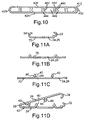
- FIG. 10 another embodiment 412, according to the present invention, of the folded tube 12 is shown. Like parts of the folded tube 12 have like reference numerals increased by four hundred (400).
- the folded tube 412 has a first side 428 and a second side 430 similar to the first side 28 and second side 30 of FIG. 1.
- the folded tube 412 also has the internal webs 440 extending between the base 424 to the top 426.
- the internal webs 440 are similar to the internal webs 40 of FIG. 1 except that the internal webs 444 may include recesses 460 or projections 462 to enhance fluid flow through the ports 442. It should be appreciated that the internal webs 440 can have a uniform or non-uniform width and may extend from the top 426 or the base 424.
- FIGS. 11A through 11D a method, according to the present invention, of the making the folded tube 12 is shown.
- the method includes the steps of providing a generally planar sheet 70 of elongate, deformable material coated with a braze material forming the base 24 and top 26 having their respective ends 32 and 34 edges along a longitudinal length thereof as illustrated in FIG. 11A.
- the ends 32 and 34 of the base 24 and top 26 can be either flat or arcuate as illustrated in FIGS. 2 through 4.
- the ends can be formed as illustrated in FIGS. 6 through 9.
- the method includes the step of folding the sheet 70 from the lateral sides to initially form the internal webs 40 with the first fold portion 44 and second fold portion 46 to an initial predetermined web height and width as illustrated in FIG. 11B.
- the method also includes the step of compressing the internal webs 40 by lateral extrusion to extend the internal webs 40 to a final predetermined web height and width as illustrated in FIG. 11C.
- the step of compressing also includes the step of forming a taper or tapered angle on the internal webs 40 and coining the internal radiuses.
- the method includes the step of folding the ends 32 and 34 toward one another until they meet to form the first side 28 and second side 30 and ports 42 as illustrated in FIG. 11D.
- the method includes the step of connecting the ends 32 and 34 together as illustrated in FIG. 2.
- the method includes the step of brazing the folded tube 12 by heating the folded tube 12 to a predetermined temperature to melt the brazing material to braze the ends 32 and 34 and the internal webs 44 to the base 24 and/or top 26.
- the folded tube 12 is then cooled to solidify the molten braze material to secure the ends 32 and 34 together and the internal webs 44 and the base 24 and top 26 together.
- the partition 150,250,350 of the folded tube 112,212,312 may be formed according to the steps disclosed in U.S. Patent No. 5,579,837, the disclosure of which is hereby incorporated by reference.
- the folded tube 412 may be formed as described above for the folded tube 12 except that the projections 462 or recesses 460 are formed during the step of compressing by the lateral extrusion.
- the folded tube 12,112,212,312,412 is a cost reduction over current tubes.
- the folded tube 12,112,212,312,412 has internal webs 40,140,240,340,440 that are folded and squeezed to maintain a predetermined distance between the top 26,126,226,326,426 and base 24,124,224,324,424.
- the folded tube 12,112,212,312,412 also has the internal webs 40,140,240,340,440 forming ports 42,142,242,342 with a hydraulic diameter preferably greater than 0.050 inches.
Landscapes
- Engineering & Computer Science (AREA)
- Mechanical Engineering (AREA)
- Physics & Mathematics (AREA)
- Thermal Sciences (AREA)
- General Engineering & Computer Science (AREA)
- Heat-Exchange Devices With Radiators And Conduit Assemblies (AREA)
Abstract
Description
- The present invention relates generally to heat exchangers for motor vehicles and, more specifically, to a folded tube and method for making same for a heat exchanger in a motor vehicle.
- It is known to provide a tube for a heat exchanger such as a condenser in an air conditioning system of a motor vehicle. The tube typically carries a first fluid medium in contact with its interior while a second fluid medium contacts its exterior. Typically, the first fluid medium is a liquid and the second fluid medium is air. Where a temperature difference exists between the first and second fluid mediums, heat will be transferred between the two via heat conductive walls of the tube.
- It is also known to provide corrugated fins or ribs in the interior of the tube to increase the surface area of conductive material available for heat transfer to cause turbulence of the fluid carried in the interior of the tube and to increase the burst strength of the tube. One known method of making such a tube is to physically insert a corrugated fin into the generally flattened tube after the tube has been manufactured. This is an extremely difficult process since the corrugated fin to be inserted into the tube is extremely thin and subject to deformation during the insertion process.
- Another known method of forming a tube for a heat exchanger is to extrude the tube in an extrusion process. In this construction, internal ribs are formed during the extrusion. However, these extruded tubes are relatively expensive to produce.
- Yet another known method of forming a tube for a heat exchanger is to provide a flat, elongated sheet with lugs and the ends of the sheet are folded to form the tube. The ends of the tube are then brazed. An example of such a tube is disclosed in U.S. Patent No. 5,386,629. In this construction, the tube may have flow paths between the lugs having a hydraulic diameter of less than 0.050 inches. Hydraulic diameter is conventionally defined as the cross-sectional area of each of the flow paths multiplied by four and divided by a wetted perimeter of the corresponding flow path. While a hydraulic diameter of less than 0.050 inches optimises heat transfer efficiency, it is relatively expensive to produce.
- Although the above tubes have worked well, they suffer from the disadvantage that the extruded tubes are relatively costly to manufacture. Another disadvantage of the above tubes is that the lugs are not folded and squeezed. Yet another disadvantage of the above tubes is that the hydraulic diameter of the flow paths are not greater than O.050 inches, making them relatively expensive to produce. Therefore, there is a need in the art to provide a folded tube for a heat exchanger of a motor vehicle that overcomes these disadvantages.
- Accordingly, the present invention is a folded tube for a heat exchanger. A folded tube includes a base, a top spaced from and opposing the base, a first side interposed between the base and the top along one side thereof, and a second side interposed between the base and the top along another side thereof. The folded tube also includes at least one of the base and the top having at least one internal web having an initial web height and being compressed to extend the at least one internal web to a final web height greater than the initial web height and defining a plurality of fluid ports.
- Also, the present invention is a method of making a folded tube for a heat exchanger. The method includes the steps of providing a generally planar sheet, folding the sheet, and forming at least one internal web having a first fold portion and a second fold portion. The method also includes the steps of compressing the at least one internal web to extend a height of the at least one internal web. The method further includes the steps of folding the sheet and forming a base and a top opposing the base and a first side interposed between the top and the base and a second side interposed between the top and the base such that the at least one internal web contacts either one of the top or the base to provide a plurality of fluid ports.
- One advantage of the present invention is that a folded tube for a heat exchanger such as a condenser is provided for an air conditioning system of a motor vehicle for condensing liquid refrigerant. Another advantage of the present invention is that the folded tube is stamped and folded and is more economical to manufacture than an extruded tube. Yet another advantage of the present invention is that the folded tube can have multiple ports or flow paths with a hydraulic diameter greater than 0.070 inches, making it relatively inexpensive to manufacture. Still another advantage of the present invention is that the folded tube is able to meet performance requirements.
- Other features and advantages of the present invention will be readily appreciated, as the same becomes better understood after reading the subsequent description taken in conjunction with the accompanying drawings.
- FIG. 1 is an elevational view of a folded tube, according to the present invention, illustrated in operational relationship with a heat exchanger of a motor vehicle.
- FIG. 2 is an enlarged perspective view of the folded tube of FIG. 1.
- FIG. 3 is an end view of the folded tube of FIG. 1.
- FIG. 4 is an enlarged view of a portion of the folded
tube in
circle 4 of FIG. 2. - FIG. 5 is an enlarged view of a portion of the folded
tube in
circle 5 of FIG. 2. - FIG. 6 is an end view of another embodiment, according to the present invention, of the folded tube of FIG. 1.
- FIG. 7 is an enlarged view of a portion of the folded
tube in
circle 7 of FIG. 6. - FIG. 8 is an end view of yet another embodiment, according to the present invention, of the folded tube of FIG. 1.
- FIG. 9 is an end view of still another embodiment, according to the present invention, of the folded tube of FIG. 1.
- FIG. 10 is an end view of still yet another embodiment, according to the present invention, of the folded tube of FIG. 1.
- FIGS. 11A through 11D are views illustrating Steps of a method, according to the present invention, of making the folded tube.
-
- Referring to the drawings and in particular FIG. 1, one embodiment of a
heat exchanger 10, such as a condenser for an air conditioning system (not shown), is shown for a motor vehicle (not shown). Theheat exchanger 10 includes a plurality of generally parallel foldedtubes 12, according to the present invention, extending between oppositely disposedheaders heat exchanger 10 includes afluid inlet 18 for conducting cooling fluid into theheat exchanger 10 formed in theheader 14 and anoutlet 20 for directing cooling fluid out theheat exchanger 10 formed in theheader 16. Theheat exchanger 10 also includes a plurality of convoluted orserpentine fins 22 attached to an exterior of each of thetubes 12. Thefins 22 are disposed between each of thetubes 12. Thefins 22 conduct heat away from thetubes 12 while providing additional surface area for convective heat transfer by air flowing over theheat exchanger 10. It should be appreciated that, except for the foldedtube 12, theheat exchanger 10 is conventional and known in the art. It should also be appreciated that the foldedtube 12 could be used for heat exchangers in other applications besides motor vehicles. - Referring to FIGS. 2 through 5, the folded
tube 12 extends longitudinally and is substantially flat. The foldedtube 12 includes abase 24 being generally planar and extending laterally. The foldedtube 12 also includes a top 26 spaced from the base 24 a predetermined distance and opposing each other. The top 26 is generally planar and extends laterally. The foldedtube 12 includes afirst side 28 interposed between thebase 24 and thetop 26 along one side thereof. Thefirst side 28 is generally arcuate in shape. The foldedtube 12 also includes asecond side 30 interposed between thebase 24 and thetop 26 along the other side and opposing thefirst side 28. The foldedtube 12 has a generally rectangular cross-sectional shape. It should be appreciated that the foldedtube 12 may have any suitable cross-sectional shape. - Referring to FIG. 4, the
second side 30 is generally arcuate in shape and formed from afirst end 32 of thebase 24 and asecond end 34 of thetop 26. Thefirst end 32 is generally arcuate in shape and has arecess 36 formed by ashoulder 38 extending inwardly. Thesecond end 34 is generally arcuate in shape and overlaps thefirst end 32 and terminates in therecess 36 to produce a substantially flush outer periphery of thesecond side 30. Thefirst side 28 has a single wall thickness while the second side has a double wall thickness for extra strength against stone chips while driving the motor vehicle. Preferably, the wall thickness for the foldedtube 12 has a maximum of 0.35 millimetres. It should be appreciated that thebase 24, top 26,first side 28 andsecond side 30 form a hollow channel or interior for the foldedtube 12. - Referring to FIGS. 2, 3 and 5, the folded
tube 12 includes at least one, preferably a plurality ofinternal webs 40 extending from either one of or both thebase 24 and top 26 to form a plurality of ports or flowpaths 42 in the interior of the foldedtube 12. In the embodiment illustrated, thebase 24 has twointernal webs 40 spaced laterally and extending longitudinally and upwardly. The top 26 has threeinternal webs 40 spaced laterally and extending longitudinally and downwardly. Theinternal webs 40 extend in alternate directions such that one of theinternal webs 40 on thebase 24 is disposed between a pair ofinternal webs 40 on the top 26 to form sixports 42. It should be appreciated that the number ofinternal webs 40 can be varied to produce the number ofports 42 desired. - Each of the
internal webs 40 extends longitudinally and has afirst portion 44 and asecond portion 46. Theinternal web 40 is formed by folding thefirst fold portion 44 andsecond fold portion 46 of thebase 24 and/or top 26 back on itself for an initial predetermined internal web height and a predetermined internal web width or thickness. In the embodiment illustrated, the initial predetermined internal web height is approximately 0.7812 mm with a uniform initial predetermined internal web width of approximately 0.68 mm. It should be appreciated that the initial predetermined web thickness is uniform. - After the
internal web 40 is initially formed, it is compressed or laterally extruded by a conventional process such as coining to extend the height of theinternal web 40. In the embodiment illustrated, theinternal web 40 has a final predetermined internal web height (h) and predetermined internal web width or thickness (w). In the embodiment illustrated, the final predetermined web height (h) is approximately 1.345 mm and the final predetermined internal web thickness (w) is approximately 0.38 mm at its peak and approximately 0.68 mm at its base. The finalinternal web 40 is tapered at a predetermined angle. The predetermined angle is zero to seven degrees and, in the embodiment illustrated, preferably the predetermined angle is approximately 6.363 degrees. It should be appreciated that the taper angles are a result of the lateral extrusion. It should also be appreciated that theinternal webs 40 have a non-uniform thickness. It should further be appreciated that theinternal webs 40 maintain a predetermined distance or spacing between the base 24 and the top 26. - The folded
tube 12 has theinternal webs 40 laterally spaced to provide theports 42 with a predetermined hydraulic diameter. The hydraulic diameter is defined as the cross-sectional area of each of the flow paths orports 40 multiplied by four and divided by a wetted perimeter of the corresponding flow path orport 42. With the present invention, the hydraulic diameter of the ports range up to and beyond 0.070 inches. The hydraulic diameter is preferably smaller than 0.050 inches but heat transfer efficiency of the tubes of the present invention remain high even when they hydraulic diameter is greater than 0.070 inches. For example, theport 42 may have a cross-sectional area of 3.71 mm and a wetted perimeter of 8.25 mm for a hydraulic diameter of 0.0708 inches or 1.798 mm. - The folded
tube 12 has its inner and outer surfaces coated with a known brazing material. As a result, the brazing material flows between thefirst end 32 of thebase 24 and thesecond end 34 of the top 26 by capillary flow action to braze the ends together. Also, the brazing material flows between the peak of theinternal webs 40 and thebase 24 and top 26 to braze them together. - Referring to FIGS. 6 and 7, another
embodiment 112, according to the present invention, of the foldedtube 12 is shown. Like parts of the foldedtube 12 have like reference numerals increased by one hundred (100). The foldedtube 112 has theinternal webs 140 extending from thebase 124 and top 126 and spaced laterally such that theinternal webs 140 on thebase 124 and top 126 contact each other. The foldedtube 112 also includes apartition 150 extending from the top 126 to thebase 124 and which defines a pair of theadjacent ports 142. Thepartition 150 includes a pair of opposing, connectingbend portions 152 disposed at a predetermined radius of curvature toward one another. Each of thebend portions 152 includes aleg portion 154 depending from each of thebend portions 152 and which contact the base 124 at terminal ends 156. The terminal ends 156 can be either flat or include a bent overportion 157. Abraze seam 158 is disposed at the top of thepartition 150 along the longitudinal length of the foldedtube 112. It should be appreciated that thepartition 150 can be formed similar to that disclosed in U.S. Patent No. 5,597,837. - Referring to FIG. 8, another
embodiment 212, according to the present invention, of the foldedtube 12 is shown. Like parts of the foldedtube 12 have like reference numerals increased by two hundred (200). The foldedtube 212 has apartition 250 similar to thepartition 150 of FIG. 6 extending from the top 226 to thebase 224 and which defines a pair of theadjacent ports 242. The foldedtube 212 also has theinternal webs 240 extending from thebase 224 and the top 226 in an alternating manner similar to theinternal webs 40 of FIG. 1. - Referring to FIG. 9, another
embodiment 312, according to the present invention, of the foldedtube 12 is shown. Like parts of the foldedtube 12 have like reference numerals increased by three hundred (300). The foldedtube 312 has apartition 350 similar to thepartition 150 of FIG. 6 extending from the top 326 to thebase 324 and which defines a pair of theadjacent ports 342. The foldedtube 312 also has theinternal webs 340 extending only from the base 324 to the top 326. The internal webs 344 are similar to theinternal webs 40 of FIG. 1. It should be appreciated that theinternal webs 240 extend from only one side of the foldedtube 312 and may extend from the top 326 to thebase 324. - Referring to FIG. 10, another
embodiment 412, according to the present invention, of the foldedtube 12 is shown. Like parts of the foldedtube 12 have like reference numerals increased by four hundred (400). The foldedtube 412 has afirst side 428 and asecond side 430 similar to thefirst side 28 andsecond side 30 of FIG. 1. The foldedtube 412 also has the internal webs 440 extending between the base 424 to the top 426. The internal webs 440 are similar to theinternal webs 40 of FIG. 1 except that theinternal webs 444 may includerecesses 460 orprojections 462 to enhance fluid flow through theports 442. It should be appreciated that the internal webs 440 can have a uniform or non-uniform width and may extend from the top 426 or thebase 424. - Referring to FIGS. 11A through 11D, a method, according to the present invention, of the making the folded
tube 12 is shown. The method includes the steps of providing a generallyplanar sheet 70 of elongate, deformable material coated with a braze material forming thebase 24 and top 26 having their respective ends 32 and 34 edges along a longitudinal length thereof as illustrated in FIG. 11A. The ends 32 and 34 of thebase 24 and top 26 can be either flat or arcuate as illustrated in FIGS. 2 through 4. Alternatively, for the foldedtube sheet 70 from the lateral sides to initially form theinternal webs 40 with thefirst fold portion 44 andsecond fold portion 46 to an initial predetermined web height and width as illustrated in FIG. 11B. The method also includes the step of compressing theinternal webs 40 by lateral extrusion to extend theinternal webs 40 to a final predetermined web height and width as illustrated in FIG. 11C. The step of compressing also includes the step of forming a taper or tapered angle on theinternal webs 40 and coining the internal radiuses. The method includes the step of folding the ends 32 and 34 toward one another until they meet to form thefirst side 28 andsecond side 30 andports 42 as illustrated in FIG. 11D. The method includes the step of connecting theends tube 12 by heating the foldedtube 12 to a predetermined temperature to melt the brazing material to braze theends internal webs 44 to thebase 24 and/or top 26. The foldedtube 12 is then cooled to solidify the molten braze material to secure theends internal webs 44 and thebase 24 and top 26 together. It should be appreciated that, instead of theends tube 412 may be formed as described above for the foldedtube 12 except that theprojections 462 orrecesses 460 are formed during the step of compressing by the lateral extrusion. - Accordingly, the folded tube 12,112,212,312,412 is a cost reduction over current tubes. The folded tube 12,112,212,312,412 has internal webs 40,140,240,340,440 that are folded and squeezed to maintain a predetermined distance between the top 26,126,226,326,426 and base 24,124,224,324,424. The folded tube 12,112,212,312,412 also has the internal webs 40,140,240,340,440 forming ports 42,142,242,342 with a hydraulic diameter preferably greater than 0.050 inches.
- The present invention has been described in an illustrative manner. It is to be understood that the terminology which has been used is intended to be in the nature of words of description rather than of limitation.
Claims (20)
- A folded tube (12) for a heat exchanger (10) comprising:a base (24,124,224,324,424);a top (26,126,226,326,426) spaced from and opposing said base(24,124,224,324,424);a first side (28,428) interposed between said base (24,124,224,324,424) and said top (26,126,226,326,426) along one side thereof;a second side (30,430) interposed between said base (24,124,224,324,424) and said top (26,126,226,326,426) along another side thereof; andat least one of said base and said top having at least one internal web (40,140,240,340,440) having an initial web height and being compressed to extend said at least one internal web (40,140,240,340,440) to a final web height greater than said initial web height and defining a plurality of fluid ports (42,142,242,342,442).
- A folded tube as set forth in claim 1 wherein the fluid ports (42,142,242,342,442) have a predetermined hydraulic diameter greater than 0.050 inches.
- A folded tube as set forth in either claim 1 or claim 2 wherein said at least one internal web has an initial web width and a final web width less that said initial web width.
- A folded tube as set forth in any preceding claim wherein said at least one internal web (40,140,240,340,440) has a first fold portion (44) and a second fold portion (46) adjacent said first fold portion (44) and being formed from one of said base (24,124,224,324,424) and said top (26,126,226,326,426).
- A folded tube as set forth in any preceding claim wherein said at least one internal web (40,140,240,340,440) is tapered at a predetermined angle.
- A folded tube as set forth in claim 5 wherein said predetermined angle is from zero to seven degrees.
- A folded tube as set forth in claim 1 wherein said base (24,124,224,324,424) includes a plurality of first internal webs (40,140,240,340,440) and said top (26,126,226,326,426) includes a plurality of second internal webs (40,140,240,340,440).
- A folded tube as set forth in claim 7 wherein said first internal webs extend in one direction and the second internal webs extend in an opposite direction.
- A folded tube as set forth in claim 7 wherein said first internal webs (140) contact said second internal webs (140).
- A folded tube as set forth in claim 7 including a partition (15) extending from said top (126) to said base (124) and defining a pair of adjacent ports (142), said partition (150) including a pair of opposing, contacting bend portions (152) and a leg portion (154) depending from each of said bend portions (152) so as to contact said base (124).
- A folded tube as set forth in claim 7 wherein said second side has a first end (32) on said base (24) and a second end (34) on said top (26) and overlapping said first end (32).
- A folded tube as set forth in claim 7 wherein said internal webs includes either one of projections (462) and recesses (460) to enhance fluid flow.
- A method of making a folded tube (12) for a heat exchanger (10) comprising the steps of:providing a generally planar sheet (70);folding the sheet and forming at least one internal web (40) having a first fold portion (44) and a second fold portion (46);compressing the at least one internal web (40) to extend a height of the at least one internal web (40); andfolding the sheet and forming a base (24) and a top (26) opposing the base (24) and a first side (28) interposed between the top and the base and a second side (30) interposed between the top (26) and the base (24) such that the at least one internal web (40) contacts either one of the top (26) or the base (24) to provide a plurality of fluid ports.
- A method as set forth in claim 13 including the step of squeezing the at least one internal web (40) to reduce a width of the at least one internal web.
- A method as set forth in claim 13 including the step of forming a taper on the at least one internal web.
- A method as set forth in claim 13 including the step of forming a plurality of internal webs (40).
- A method as set forth in claim 16 including the step of alternating the internal webs (40) to extend in opposite directions.
- A method as set forth in claim 16 wherein said step of forming the internal webs (40) to extend in only one direction.
- A method as set forth in claim 16 wherein said step of providing the sheet with terminal ends and folding the terminal ends toward each other to form a partition (150) between a pair of adjacent internal webs.
- A method as set forth in claim 16 including the step of providing the sheet with terminal ends and folding the terminal ends toward each other in an overlapping manner to form the second side.
Applications Claiming Priority (2)
| Application Number | Priority Date | Filing Date | Title |
|---|---|---|---|
| US09/365,030 US6209202B1 (en) | 1999-08-02 | 1999-08-02 | Folded tube for a heat exchanger and method of making same |
| US365030 | 1999-08-02 |
Publications (2)
| Publication Number | Publication Date |
|---|---|
| EP1074807A2 true EP1074807A2 (en) | 2001-02-07 |
| EP1074807A3 EP1074807A3 (en) | 2001-04-11 |
Family
ID=23437188
Family Applications (1)
| Application Number | Title | Priority Date | Filing Date |
|---|---|---|---|
| EP00305595A Withdrawn EP1074807A3 (en) | 1999-08-02 | 2000-07-03 | Folded tube for a heat exchanger and method of making same |
Country Status (3)
| Country | Link |
|---|---|
| US (1) | US6209202B1 (en) |
| EP (1) | EP1074807A3 (en) |
| KR (1) | KR20010021166A (en) |
Cited By (26)
| Publication number | Priority date | Publication date | Assignee | Title |
|---|---|---|---|---|
| EP1253391A1 (en) | 2001-04-28 | 2002-10-30 | Behr GmbH & Co. | Folded flat tube with multiple cavities |
| WO2003060410A1 (en) * | 2002-01-17 | 2003-07-24 | Behr Gmbh & Co. | Multi-chamber flat tube |
| WO2003078911A3 (en) * | 2002-03-20 | 2004-03-11 | Behr Gmbh & Co | Heat exchanger and cooling system |
| FR2847974A1 (en) * | 2002-12-03 | 2004-06-04 | Valeo Climatisation | Heat exchanger tubes with flow perturbation, uses rectangular section tubes with raised spoiler surfaces on opposite internal faces of the tubes |
| EP1489372A1 (en) * | 2003-06-21 | 2004-12-22 | Modine Manufacturing Company | Flat tube for a heat exchanger |
| DE102004049809A1 (en) * | 2004-10-12 | 2006-04-13 | Behr Gmbh & Co. Kg | Flat tube for heat exchanger |
| WO2006045415A1 (en) * | 2004-10-22 | 2006-05-04 | Aleris Aluminum Koblenz Gmbh | Tube made of a profile rolled metal product and method of producing the same |
| WO2007044300A2 (en) | 2005-10-04 | 2007-04-19 | Federal-Mogul Corporation | Sheet metal joint |
| DE102006002627A1 (en) * | 2006-01-19 | 2007-08-02 | Modine Manufacturing Co., Racine | Heat exchanger tube has internal chamber extends from center of tube past location to interior surface of second narrow side |
| EP1630513A3 (en) * | 2004-08-24 | 2008-04-16 | Behr GmbH & Co. KG | Flat tube for heat exchanger, in particular for vehicles and method for producing the same |
| DE102006054814A1 (en) * | 2006-11-22 | 2008-05-29 | Modine Manufacturing Co., Racine | Soldered flat tube for capacitors and / or evaporators |
| KR100863722B1 (en) * | 2001-10-05 | 2008-10-15 | 한라공조주식회사 | Plate for 2 tank type heat exchanger |
| DE102009021888A1 (en) * | 2009-05-19 | 2010-12-02 | Liebherr-Hausgeräte Ochsenhausen GmbH | Heat exchanger for cooling or freezing equipment, has multiple parallel channels flowed through refrigerant, by which each channel has certain hydraulic diameter |
| US7921559B2 (en) | 2006-01-19 | 2011-04-12 | Modine Manufacturing Company | Flat tube, flat tube heat exchanger, and method of manufacturing same |
| US8091621B2 (en) | 2006-01-19 | 2012-01-10 | Modine Manufacturing Company | Flat tube, flat tube heat exchanger, and method of manufacturing same |
| WO2012007452A1 (en) * | 2010-07-16 | 2012-01-19 | Behr Gmbh & Co. Kg | Solderable fluid channel for a heat exchanger of aluminium |
| CN101377392B (en) * | 2007-08-27 | 2012-02-22 | Abb研究有限公司 | heat exchanger |
| US8191258B2 (en) | 2006-01-19 | 2012-06-05 | Modine Manufacturing Company | Flat tube, flat tube heat exchanger, and method of manufacturing same |
| US8281489B2 (en) | 2006-01-19 | 2012-10-09 | Modine Manufacturing Company | Flat tube, flat tube heat exchanger, and method of manufacturing same |
| US8434227B2 (en) | 2006-01-19 | 2013-05-07 | Modine Manufacturing Company | Method of forming heat exchanger tubes |
| US8438728B2 (en) | 2006-01-19 | 2013-05-14 | Modine Manufacturing Company | Flat tube, flat tube heat exchanger, and method of manufacturing same |
| CN103492827A (en) * | 2011-01-31 | 2014-01-01 | 德尔福技术有限公司 | Method of fabricating a double-nosed tube for a heat exchanger |
| US8683690B2 (en) | 2006-01-19 | 2014-04-01 | Modine Manufacturing Company | Flat tube, flat tube heat exchanger, and method of manufacturing same |
| US8726508B2 (en) | 2006-01-19 | 2014-05-20 | Modine Manufacturing Company | Flat tube, flat tube heat exchanger, and method of manufacturing same |
| US9038267B2 (en) | 2010-06-10 | 2015-05-26 | Modine Manufacturing Company | Method of separating heat exchanger tubes and an apparatus for same |
| EP4151942A1 (en) * | 2021-09-15 | 2023-03-22 | MAHLE International GmbH | Flat tube |
Families Citing this family (41)
| Publication number | Priority date | Publication date | Assignee | Title |
|---|---|---|---|---|
| EP1058070A3 (en) * | 1999-06-04 | 2002-07-31 | Denso Corporation | Refrigerant evaporator |
| SE521816C2 (en) | 1999-06-18 | 2003-12-09 | Valeo Engine Cooling Ab | Fluid transport pipes and vehicle coolers |
| SE517450C2 (en) * | 1999-06-18 | 2002-06-04 | Valeo Engine Cooling Ab | Fluid transport tubes and methods and apparatus for producing the same |
| US6449979B1 (en) * | 1999-07-02 | 2002-09-17 | Denso Corporation | Refrigerant evaporator with refrigerant distribution |
| GB2361301B (en) * | 2000-03-16 | 2003-10-08 | Denso Corp | Self clamping groove in a seamed tube |
| GB0101697D0 (en) * | 2001-01-23 | 2001-03-07 | Emerson & Renwick Ltd | Heat exchanger tube |
| JP5250924B2 (en) * | 2001-07-16 | 2013-07-31 | 株式会社デンソー | Exhaust heat exchanger |
| DE10201511A1 (en) * | 2002-01-17 | 2003-07-31 | Behr Gmbh & Co | Welded multi-chamber tube |
| US6615488B2 (en) * | 2002-02-04 | 2003-09-09 | Delphi Technologies, Inc. | Method of forming heat exchanger tube |
| AU2003272090B2 (en) * | 2002-10-02 | 2008-08-07 | Showa Denko K.K. | Heat exchanging tube and heat exchanger |
| DE10343905A1 (en) * | 2003-09-19 | 2005-06-09 | Behr Gmbh & Co. Kg | Soldered heat transfer network |
| US7073570B2 (en) * | 2003-09-22 | 2006-07-11 | Visteon Global Technologies, Inc. | Automotive heat exchanger |
| US20050092476A1 (en) * | 2003-10-31 | 2005-05-05 | Valeo Inc | Folded tube for a heat exchanger and method of making same |
| US7316263B2 (en) * | 2003-11-19 | 2008-01-08 | Intel Corporation | Cold plate |
| FR2869679A1 (en) | 2004-04-29 | 2005-11-04 | Valeo Climatisation Sa | Tube for e.g. evaporator, has metallic strip with reduced thickness forming longitudinal groove on inner surface of casing, where groove has width in order to house support portion of partitioning unit |
| US20090019696A1 (en) * | 2006-01-19 | 2009-01-22 | Werner Zobel | Flat tube, flat tube heat exchanger, and method of manufacturing same |
| CN101405556B (en) * | 2006-01-19 | 2013-03-20 | 摩丁制造公司 | Flat tube, flat tube heat exchanger and manufacturing method thereof |
| US20090014165A1 (en) * | 2006-01-19 | 2009-01-15 | Werner Zobel | Flat tube, flat tube heat exchanger, and method of manufacturing same |
| JP2007198623A (en) * | 2006-01-24 | 2007-08-09 | Denso Corp | Heat exchanger |
| DE102007004993A1 (en) * | 2007-02-01 | 2008-08-07 | Modine Manufacturing Co., Racine | Production process for flat tubes and roller mill |
| DE102008007600A1 (en) | 2008-02-04 | 2009-08-06 | Behr Gmbh & Co. Kg | Multiple chamber-flat tube for heat exchangers such as heaters, evaporators and condensers, has two chambers for receiving flow of fluids, and chambers are manufactured by shaping metal band |
| DE102008007601A1 (en) | 2008-02-04 | 2009-08-06 | Behr Gmbh & Co. Kg | Multi-chamber flat pipe has two chambers for flow admission of fluid, where chambers are manufactured, particularly in bend or folding method, by forming broad strip |
| DE102008007610A1 (en) | 2008-02-04 | 2009-08-06 | Behr Gmbh & Co. Kg | Multi-chamber flat tube for use in e.g. high temperature heat exchanger, to exchange heat between exhaust gas and coolant in motor vehicle, has bar with edge portions partially formed as part of side sections of metal strip |
| DE102008007597A1 (en) | 2008-02-04 | 2009-08-06 | Behr Gmbh & Co. Kg | Multi-chamber flat pipe manufacturing method for heat exchanger e.g. exhaust gas heat exchanger, involves attaching bar to edge area of strip through shaping, and forming strip for forming flat pipe, such that profile is closed |
| DE102008007611A1 (en) | 2008-02-04 | 2009-08-06 | Behr Gmbh & Co. Kg | Multi-chamber flat pipe for use in e.g. exhaust gas cooler, in internal-combustion engine of motor vehicle, has bar formed with edge sections of side section of metal strip and part of edge sections forming arrangement for bar flap |
| DE102008007587A1 (en) | 2008-02-04 | 2009-08-06 | Behr Gmbh & Co. Kg | Multi-chamber automotive heat exchanger or radiator has flat tube inner chamber sub-divided by U-shaped cross-piece |
| DE102008007612A1 (en) | 2008-02-04 | 2009-08-06 | Behr Gmbh & Co. Kg | Multi-chamber flat pipe for use in heat exchanger utilized as e.g. exhaust gas cooler in internal-combustion engine of motor vehicle, has metal strip whose edge section and/or inner section lies against contact area of one of broad walls |
| US8281475B2 (en) | 2009-10-05 | 2012-10-09 | Federal-Mogul World Wide, Inc. | Sheet metal joint |
| PL2375208T3 (en) * | 2010-03-31 | 2013-05-31 | Valeo Autosystemy Sp Zoo | Improved heat exchanger |
| GB2509762B (en) * | 2013-01-14 | 2015-02-04 | Halla Visteon Climate Control | Tube for Heat Exchanger |
| US9453599B2 (en) * | 2013-06-21 | 2016-09-27 | Ford Global Technologies, Llc | Bi-channel coolant tube having crossover channels to allow coolant interaction |
| JP6194700B2 (en) * | 2013-08-30 | 2017-09-13 | 富士通株式会社 | Radiator and method of manufacturing radiator |
| CN106030232B (en) * | 2014-02-21 | 2019-06-04 | 翰昂系统株式会社 | Pipes for heat exchangers |
| EP3397914B1 (en) | 2015-12-28 | 2020-09-23 | Carrier Corporation | Folded conduit for heat exchanger applications |
| DE102018111585A1 (en) * | 2017-06-22 | 2018-12-27 | Hanon Systems | Heat transfer device and method of manufacturing the device |
| US11168943B2 (en) * | 2018-10-12 | 2021-11-09 | Api Heat Transfer Thermasys Corporation | Channel fin heat exchangers and methods of manufacturing the same |
| WO2020132202A1 (en) | 2018-12-19 | 2020-06-25 | Carrier Corporation | Heat exchanger with aluminum alloy clad tube and method of manufacture |
| LU101492B1 (en) * | 2019-11-25 | 2021-05-26 | Ht Holding Luxembourg S A | Flat heat exchanger tube |
| US12341082B2 (en) * | 2021-08-06 | 2025-06-24 | Baidu Usa Llc | Chip cooling package with multiple fluid paths |
| US20230138731A1 (en) | 2021-11-02 | 2023-05-04 | Carrier Corporation | Fabricated heat exchange tube for microchannel heat exchanger |
| WO2025221763A1 (en) * | 2024-04-16 | 2025-10-23 | Modine Manufacturing Company | Heat exchanger having a multicavity tube |
Citations (2)
| Publication number | Priority date | Publication date | Assignee | Title |
|---|---|---|---|---|
| US5386629A (en) | 1990-05-11 | 1995-02-07 | Showa Aluminum Kabushiki Kaisha | Tube for heat exchangers and a method for manufacturing the tube |
| EP1014024A1 (en) * | 1997-08-08 | 2000-06-28 | Zexel Corporation | Tube for heat exchangers and method of manufacturing same |
Family Cites Families (63)
| Publication number | Priority date | Publication date | Assignee | Title |
|---|---|---|---|---|
| US349060A (en) | 1886-09-14 | P- serve | ||
| US1316199A (en) | 1919-09-16 | Philmobb iv spebt | ||
| FR359192A (en) | 1905-11-06 | 1906-03-17 | Thirion Et Mottant Soc | Finned tube |
| GB190819219A (en) * | 1908-09-12 | 1909-08-26 | Guglielmo Febbraro | Improvements in Radiators or Water Coolers for Motor Driven Vehicles. |
| US992763A (en) | 1910-05-19 | 1911-05-23 | Theodore C Fedders | Radiator. |
| US1302627A (en) | 1915-05-17 | 1919-05-06 | Kinderman M Boblett | Automobile-radiator. |
| GB191512067A (en) | 1915-08-21 | 1916-08-03 | John Harvey | Improvements in or relating to Radiators for Motor Vehicles and the like. |
| FR545200A (en) | 1921-12-23 | 1922-10-06 | Moreux & Co G | Manufacturing process of elements for heat exchangers |
| FR582898A (en) | 1923-09-24 | 1924-12-30 | Improvements to cooling radiators and their manufacturing processes | |
| GB247935A (en) * | 1925-02-20 | 1926-07-29 | Chausson Usines Sa | Improvements in radiators for internal combustion engines |
| US2017201A (en) | 1931-11-27 | 1935-10-15 | Modine Mfg Co | Condenser tube |
| US2043496A (en) | 1932-09-19 | 1936-06-09 | Baker Ice Machine Co Inc | Evaporator for refrigeration systems |
| US2093256A (en) | 1935-01-10 | 1937-09-14 | Still William Joseph | Heat exchange element |
| US2151540A (en) | 1935-06-19 | 1939-03-21 | Varga Alexander | Heat exchanger and method of making same |
| GB528297A (en) | 1938-07-12 | 1940-10-25 | Dewandre Co Ltd C | Improvements in or relating to heat exchange elements |
| US2321755A (en) | 1939-08-05 | 1943-06-15 | Detroit Harvester Co | Device for connecting sheet metal panels |
| US2396522A (en) | 1943-04-19 | 1946-03-12 | Modine Mfg Co | Radiator tube construction |
| US2462136A (en) | 1945-05-24 | 1949-02-22 | Samuel H Smith | Heat exchanger and method of making same |
| US2554185A (en) | 1949-01-15 | 1951-05-22 | Gen Electric | Multisectioned radiator |
| US2663072A (en) | 1949-03-16 | 1953-12-22 | Pfistershammer Josef | Process for joining sheet metal or the like |
| GB683161A (en) | 1950-07-22 | 1952-11-26 | Morris Motors Ltd | Improvements relating to heat-exchangers |
| FR1140305A (en) | 1955-01-21 | 1957-07-19 | Morris Motors Ltd | Brazed light alloy automotive radiator tubes |
| US2825996A (en) | 1956-03-06 | 1958-03-11 | Philip J Grant | Insecticide container |
| DE1094277B (en) | 1956-12-15 | 1960-12-08 | Appbau Rothemuehle Dr Brandt & | Plates for regenerative heat exchangers |
| US3258832A (en) | 1962-05-14 | 1966-07-05 | Gen Motors Corp | Method of making sheet metal heat exchangers |
| US3341925A (en) | 1963-06-26 | 1967-09-19 | Gen Motors Corp | Method of making sheet metal heat exchangers with air centers |
| AT271829B (en) * | 1966-08-09 | 1969-06-10 | Voest Ag | Folded tube and method and device for the production of foldable tubes |
| US3603384A (en) | 1969-04-08 | 1971-09-07 | Modine Mfg Co | Expandable tube, and heat exchanger |
| US3662582A (en) | 1970-05-18 | 1972-05-16 | Noranda Metal Ind | Heat-exchange tubing and method of making it |
| US3757856A (en) | 1971-10-15 | 1973-09-11 | Union Carbide Corp | Primary surface heat exchanger and manufacture thereof |
| US4002201A (en) | 1974-05-24 | 1977-01-11 | Borg-Warner Corporation | Multiple fluid stacked plate heat exchanger |
| JPS597446A (en) | 1982-07-02 | 1984-01-14 | Nippon Denso Co Ltd | Manufacture of heat exchanger |
| JPS59129392A (en) | 1983-01-10 | 1984-07-25 | Nippon Denso Co Ltd | Heat exchanger |
| DE3419734A1 (en) | 1984-05-26 | 1985-11-28 | GEA Luftkühlergesellschaft Happel GmbH & Co, 4630 Bochum | AIR COOLED SURFACE CAPACITOR |
| JPS616107U (en) | 1984-06-15 | 1986-01-14 | シャープ株式会社 | Microwave oven structure |
| JPS6166091A (en) | 1984-09-06 | 1986-04-04 | Toyo Radiator Kk | Manufacture of heat exchanger tube material and core by use of such material and core by use of such material |
| US4998580A (en) | 1985-10-02 | 1991-03-12 | Modine Manufacturing Company | Condenser with small hydraulic diameter flow path |
| US5372188A (en) | 1985-10-02 | 1994-12-13 | Modine Manufacturing Co. | Heat exchanger for a refrigerant system |
| DE3610618A1 (en) | 1986-03-29 | 1987-10-01 | Mtu Muenchen Gmbh | PROFILE TUBE WITH ELLIPTICAL OR LANZETT-SHAPED SECTION FOR TUBE HEAT EXCHANGER AND METHOD FOR THE PRODUCTION THEREOF |
| US4825941B1 (en) | 1986-07-29 | 1997-07-01 | Showa Aluminum Corp | Condenser for use in a car cooling system |
| US4805693A (en) | 1986-11-20 | 1989-02-21 | Modine Manufacturing | Multiple piece tube assembly for use in heat exchangers |
| DE3725602A1 (en) * | 1987-08-01 | 1989-02-09 | Sueddeutsche Kuehler Behr | FLAT TUBE FOR A HEAT EXCHANGER |
| JPH0284252A (en) | 1988-06-10 | 1990-03-26 | Matsushita Seiko Co Ltd | Heat exchanger tube and its manufacturing method |
| JP2589765B2 (en) | 1988-06-10 | 1997-03-12 | 松下冷機株式会社 | Heat transfer tube manufacturing method |
| US4982784A (en) | 1988-09-30 | 1991-01-08 | Ford Motor Company | Composite heat exchanger tube |
| US4932469A (en) | 1989-10-04 | 1990-06-12 | Blackstone Corporation | Automotive condenser |
| JP2968807B2 (en) | 1989-11-14 | 1999-11-02 | カルソニック株式会社 | Heat transfer tube for heat exchanger and method of manufacturing the same |
| US5271151A (en) | 1990-04-23 | 1993-12-21 | Wallis Bernard J | Method of making a high pressure condenser |
| JPH0545082A (en) * | 1991-08-12 | 1993-02-23 | Showa Alum Corp | Heat exchanger tube |
| US5172476A (en) | 1991-08-14 | 1992-12-22 | General Motors Corporation | Method of manufacturing heat exchanger tubing |
| US5295302A (en) | 1991-10-29 | 1994-03-22 | Calsonic Corporation | Method of manufacturing an aluminum heat exchanger |
| JP2915660B2 (en) | 1991-12-18 | 1999-07-05 | 昭和アルミニウム株式会社 | Tube for heat exchanger and manufacturing method |
| JP3311001B2 (en) * | 1991-12-27 | 2002-08-05 | 昭和電工株式会社 | Method of manufacturing tubes for heat exchangers |
| US5185925A (en) | 1992-01-29 | 1993-02-16 | General Motors Corporation | Method of manufacturing a tube for a heat exchanger |
| GB2268260A (en) * | 1992-06-24 | 1994-01-05 | Llanelli Radiators Ltd | Heat exchange tubes formed from a unitary portion of sheet or strip material |
| JP3329906B2 (en) | 1993-10-29 | 2002-09-30 | 株式会社ゼクセルヴァレオクライメートコントロール | Flat tubes of heat exchanger |
| JPH07227631A (en) | 1993-12-21 | 1995-08-29 | Zexel Corp | Guide tube for heat exchanging in laminated layer type heat exchanger and its manufacture |
| JPH08200977A (en) | 1995-01-27 | 1996-08-09 | Zexel Corp | Flat tube for heat exchanger and manufacture thereof |
| US5579837A (en) | 1995-11-15 | 1996-12-03 | Ford Motor Company | Heat exchanger tube and method of making the same |
| JPH10318695A (en) | 1997-05-19 | 1998-12-04 | Zexel Corp | Heat exchanger |
| US5996205A (en) * | 1997-06-11 | 1999-12-07 | Calsonic Corporation | Method for manufacturing a pipe with a partition |
| JPH1130493A (en) * | 1997-07-09 | 1999-02-02 | Zexel Corp | Tube for heat exchange and manufacture thereof |
| JP3299148B2 (en) * | 1997-09-16 | 2002-07-08 | 株式会社ゼクセルヴァレオクライメートコントロール | Tube for heat exchanger and method for producing the same |
-
1999
- 1999-08-02 US US09/365,030 patent/US6209202B1/en not_active Expired - Fee Related
-
2000
- 2000-07-03 EP EP00305595A patent/EP1074807A3/en not_active Withdrawn
- 2000-08-01 KR KR1020000044486A patent/KR20010021166A/en not_active Ceased
Patent Citations (2)
| Publication number | Priority date | Publication date | Assignee | Title |
|---|---|---|---|---|
| US5386629A (en) | 1990-05-11 | 1995-02-07 | Showa Aluminum Kabushiki Kaisha | Tube for heat exchangers and a method for manufacturing the tube |
| EP1014024A1 (en) * | 1997-08-08 | 2000-06-28 | Zexel Corporation | Tube for heat exchangers and method of manufacturing same |
Cited By (36)
| Publication number | Priority date | Publication date | Assignee | Title |
|---|---|---|---|---|
| EP1253391A1 (en) | 2001-04-28 | 2002-10-30 | Behr GmbH & Co. | Folded flat tube with multiple cavities |
| US6622785B2 (en) | 2001-04-28 | 2003-09-23 | Behr Gmbh & Co. | Folded multi-passageway flat tube |
| KR100863722B1 (en) * | 2001-10-05 | 2008-10-15 | 한라공조주식회사 | Plate for 2 tank type heat exchanger |
| WO2003060410A1 (en) * | 2002-01-17 | 2003-07-24 | Behr Gmbh & Co. | Multi-chamber flat tube |
| WO2003078911A3 (en) * | 2002-03-20 | 2004-03-11 | Behr Gmbh & Co | Heat exchanger and cooling system |
| CN100573016C (en) * | 2002-03-20 | 2009-12-23 | 贝洱两合公司 | Heat exchanger and cooling system |
| FR2847974A1 (en) * | 2002-12-03 | 2004-06-04 | Valeo Climatisation | Heat exchanger tubes with flow perturbation, uses rectangular section tubes with raised spoiler surfaces on opposite internal faces of the tubes |
| WO2004053410A3 (en) * | 2002-12-03 | 2004-08-12 | Valeo Climatisation | Radiator tubes comprising turbulence generating elements and associated radiators |
| EP1489372B1 (en) | 2003-06-21 | 2016-04-13 | Modine Manufacturing Company | Flat tube for a heat exchanger |
| EP1489372A1 (en) * | 2003-06-21 | 2004-12-22 | Modine Manufacturing Company | Flat tube for a heat exchanger |
| US7665512B2 (en) | 2003-06-21 | 2010-02-23 | Modine Manufacturing Company | Flat heat exchanger tube |
| EP1630513A3 (en) * | 2004-08-24 | 2008-04-16 | Behr GmbH & Co. KG | Flat tube for heat exchanger, in particular for vehicles and method for producing the same |
| DE102004049809A1 (en) * | 2004-10-12 | 2006-04-13 | Behr Gmbh & Co. Kg | Flat tube for heat exchanger |
| WO2006045415A1 (en) * | 2004-10-22 | 2006-05-04 | Aleris Aluminum Koblenz Gmbh | Tube made of a profile rolled metal product and method of producing the same |
| US7690114B2 (en) | 2004-10-22 | 2010-04-06 | Aleris Aluminum Koblenz Gmbh | Tube having reinforcing structures made of profile rolled metal and method of producing same |
| WO2007044300A2 (en) | 2005-10-04 | 2007-04-19 | Federal-Mogul Corporation | Sheet metal joint |
| CN101321961B (en) * | 2005-10-04 | 2012-04-25 | 费德罗-莫格尔公司 | Sheet metal joint |
| EP1931884A4 (en) * | 2005-10-04 | 2010-03-03 | Federal Mogul Corp | Sheet metal joint |
| US8438728B2 (en) | 2006-01-19 | 2013-05-14 | Modine Manufacturing Company | Flat tube, flat tube heat exchanger, and method of manufacturing same |
| US8683690B2 (en) | 2006-01-19 | 2014-04-01 | Modine Manufacturing Company | Flat tube, flat tube heat exchanger, and method of manufacturing same |
| US8091621B2 (en) | 2006-01-19 | 2012-01-10 | Modine Manufacturing Company | Flat tube, flat tube heat exchanger, and method of manufacturing same |
| DE102006002627A1 (en) * | 2006-01-19 | 2007-08-02 | Modine Manufacturing Co., Racine | Heat exchanger tube has internal chamber extends from center of tube past location to interior surface of second narrow side |
| US7921559B2 (en) | 2006-01-19 | 2011-04-12 | Modine Manufacturing Company | Flat tube, flat tube heat exchanger, and method of manufacturing same |
| US8191258B2 (en) | 2006-01-19 | 2012-06-05 | Modine Manufacturing Company | Flat tube, flat tube heat exchanger, and method of manufacturing same |
| US8281489B2 (en) | 2006-01-19 | 2012-10-09 | Modine Manufacturing Company | Flat tube, flat tube heat exchanger, and method of manufacturing same |
| US8434227B2 (en) | 2006-01-19 | 2013-05-07 | Modine Manufacturing Company | Method of forming heat exchanger tubes |
| US8726508B2 (en) | 2006-01-19 | 2014-05-20 | Modine Manufacturing Company | Flat tube, flat tube heat exchanger, and method of manufacturing same |
| DE102006054814A1 (en) * | 2006-11-22 | 2008-05-29 | Modine Manufacturing Co., Racine | Soldered flat tube for capacitors and / or evaporators |
| CN101377392B (en) * | 2007-08-27 | 2012-02-22 | Abb研究有限公司 | heat exchanger |
| DE102009021888A1 (en) * | 2009-05-19 | 2010-12-02 | Liebherr-Hausgeräte Ochsenhausen GmbH | Heat exchanger for cooling or freezing equipment, has multiple parallel channels flowed through refrigerant, by which each channel has certain hydraulic diameter |
| US9038267B2 (en) | 2010-06-10 | 2015-05-26 | Modine Manufacturing Company | Method of separating heat exchanger tubes and an apparatus for same |
| WO2012007452A1 (en) * | 2010-07-16 | 2012-01-19 | Behr Gmbh & Co. Kg | Solderable fluid channel for a heat exchanger of aluminium |
| US10222145B2 (en) | 2010-07-16 | 2019-03-05 | Mahle International Gmbh | Solderable fluid channel for a heat exchanger of aluminum |
| CN103492827A (en) * | 2011-01-31 | 2014-01-01 | 德尔福技术有限公司 | Method of fabricating a double-nosed tube for a heat exchanger |
| CN103492827B (en) * | 2011-01-31 | 2016-06-29 | 马勒国际有限公司 | The method manufacturing the double; two nose pipe fittings for heat exchanger |
| EP4151942A1 (en) * | 2021-09-15 | 2023-03-22 | MAHLE International GmbH | Flat tube |
Also Published As
| Publication number | Publication date |
|---|---|
| KR20010021166A (en) | 2001-03-15 |
| US6209202B1 (en) | 2001-04-03 |
| EP1074807A3 (en) | 2001-04-11 |
Similar Documents
| Publication | Publication Date | Title |
|---|---|---|
| US6209202B1 (en) | Folded tube for a heat exchanger and method of making same | |
| US5579837A (en) | Heat exchanger tube and method of making the same | |
| US7182128B2 (en) | Heat exchanger tube having strengthening deformations | |
| EP0360362B1 (en) | Condenser | |
| EP1231448B1 (en) | Heat exchanger | |
| US4936379A (en) | Condenser for use in a car cooling system | |
| EP1065466B1 (en) | Flat turbulator for a tube and method of making same | |
| US6595273B2 (en) | Heat exchanger | |
| JP4171760B2 (en) | Flat tube and manufacturing method of flat tube | |
| US20060070726A1 (en) | Plate fin for heat exchanger and heat exchanger core | |
| EP0881449A2 (en) | Refrigerant tubes for heat exchangers | |
| KR950007282B1 (en) | Capacitors with subdivided flow paths | |
| US6216777B1 (en) | Manifold for a heat exchanger and method of making same | |
| US6241012B1 (en) | Folded tube for a heat exchanger and method of making same | |
| US5890288A (en) | Method for making a heat exchanger tube | |
| US5934365A (en) | Heat exchanger | |
| JP3870865B2 (en) | Heat exchanger | |
| US20030066635A1 (en) | Turbulator with offset louvers and method of making same | |
| US6612031B2 (en) | Tube for a heat exchanger and method of making same | |
| US6438840B2 (en) | Method of making continuous corrugated heat exchanger | |
| EP1067350B1 (en) | Beaded plate for a heat exchanger and method of making same | |
| US20060162919A1 (en) | Flat tube and process for producing heat exchanger with use of the flat tube | |
| JP4751662B2 (en) | Plate for manufacturing flat tube, method for manufacturing flat tube, and method for manufacturing heat exchanger | |
| JPS6317391A (en) | Heat exchanger and manufacture thereof | |
| JPS63282490A (en) | Manufacture of heat exchanger |
Legal Events
| Date | Code | Title | Description |
|---|---|---|---|
| PUAI | Public reference made under article 153(3) epc to a published international application that has entered the european phase |
Free format text: ORIGINAL CODE: 0009012 |
|
| AK | Designated contracting states |
Kind code of ref document: A2 Designated state(s): DE FR GB |
|
| AX | Request for extension of the european patent |
Free format text: AL;LT;LV;MK;RO;SI |
|
| PUAL | Search report despatched |
Free format text: ORIGINAL CODE: 0009013 |
|
| AK | Designated contracting states |
Kind code of ref document: A3 Designated state(s): AT BE CH CY DE DK ES FI FR GB GR IE IT LI LU MC NL PT SE |
|
| AX | Request for extension of the european patent |
Free format text: AL;LT;LV;MK;RO;SI |
|
| RIC1 | Information provided on ipc code assigned before grant |
Free format text: 7F 28D 1/03 A, 7F 28F 3/04 B, 7B 21C 37/08 B, 7B 21C 37/15 B |
|
| 17P | Request for examination filed |
Effective date: 20010915 |
|
| AKX | Designation fees paid |
Free format text: DE FR GB |
|
| 17Q | First examination report despatched |
Effective date: 20061222 |
|
| STAA | Information on the status of an ep patent application or granted ep patent |
Free format text: STATUS: THE APPLICATION IS DEEMED TO BE WITHDRAWN |
|
| 18D | Application deemed to be withdrawn |
Effective date: 20090203 |