EP1072436A1 - Device for grinding the backs of book blocks in a casing-in machine - Google Patents
Device for grinding the backs of book blocks in a casing-in machine Download PDFInfo
- Publication number
- EP1072436A1 EP1072436A1 EP99810661A EP99810661A EP1072436A1 EP 1072436 A1 EP1072436 A1 EP 1072436A1 EP 99810661 A EP99810661 A EP 99810661A EP 99810661 A EP99810661 A EP 99810661A EP 1072436 A1 EP1072436 A1 EP 1072436A1
- Authority
- EP
- European Patent Office
- Prior art keywords
- rollers
- book
- slide
- conveyor
- grinder
- Prior art date
- Legal status (The legal status is an assumption and is not a legal conclusion. Google has not performed a legal analysis and makes no representation as to the accuracy of the status listed.)
- Granted
Links
Images


Classifications
-
- B—PERFORMING OPERATIONS; TRANSPORTING
- B42—BOOKBINDING; ALBUMS; FILES; SPECIAL PRINTED MATTER
- B42C—BOOKBINDING
- B42C11/00—Casing-in
- B42C11/04—Machines or equipment for casing-in or applying covers to books
Landscapes
- Engineering & Computer Science (AREA)
- Mechanical Engineering (AREA)
- Soil Working Implements (AREA)
- Finish Polishing, Edge Sharpening, And Grinding By Specific Grinding Devices (AREA)
- Folding Of Thin Sheet-Like Materials, Special Discharging Devices, And Others (AREA)
- Feeding Of Articles By Means Other Than Belts Or Rollers (AREA)
- Devices For Conveying Motion By Means Of Endless Flexible Members (AREA)
- Toys (AREA)
- Rollers For Roller Conveyors For Transfer (AREA)
Abstract
Description
Die Erfindung betrifft eine Einrichtung für das Anreiben einer Buchdecke an den beleimten Aussenflächen von in einer Buchblokkeinhängemaschine in Buchdecken einzuhängenden Buchblocks, bestehend aus zwei sich in einem Anreibbereich gegenüberliegenden, jeweils einen Buchdeckel der Buchdecke an eine beleimte Aussenfläche eines auf einer senkrecht nach oben bewegten Sattelplatte eines umlaufenden Förderers fortbewegten Buchblocks anpressenden Anreibwalzen einer mit dem Förderer antriebsverbunden gesteuerten Anreibevorrichtung.The invention relates to a device for rubbing a Book cover on the glued outer surfaces of in a book block hanging machine book blocks to be hung in book covers from two opposite one another in a rubbing area, one cover each of the book cover to a glued one Outside surface of a saddle plate moved vertically upwards of a circulating conveyor moving book block pressing rollers of a drive connected to the conveyor controlled grinder.
Das Einstellen der Anreibevorrichtung zum transportierten Buchblock ist in einer Bucheinhängemaschine, wie sie beispielsweise in der EP - A - 0 198 201 und DE - A - 37 13 896 beschrieben ist, mit einem zeitraubenden Arbeitsaufwand verbunden und nur bei stehender Maschine möglich. Hierzu ist der Antrieb der Anreibevorrichtung von den Hauptantrieb zu lösen, um die Anreibwalzen auf die Breite eines auf einer Sattelplatte geförderten Buchblocks ausrichten zu können.The setting of the rubbing device for the transported book block is in a book hanging machine, like for example in EP-A-0 198 201 and DE-A-37 13 896 is associated with a time-consuming workload and only possible with the machine stopped. This is the drive of the grinder from the main drive to release the grinder rollers to the width of a conveyed on a saddle plate Align book blocks.
Buchblockeinhängemaschinen können bekanntlich mehr als ein Anreibwalzenpaar in einer Anreibevorrichtung aufweisen, wobei das in Förderrichtung der Buchblocks vorderste Anreibwalzenpaar resp. das zuerst auf einen Buchblock einwirkende Anreibwalzenpaar auf den Buchblock eingestellt wird und das nachgeschaltete Anreibwalzenpaar lediglich eine Anreibfunktion ausübt.It is known that book block hook-in machines can do more than a pair of grinder rollers have in a grinder, the foremost in the conveying direction of the book blocks resp. the pair of grinder rollers first acting on a book block is set on the book block and the downstream Grinding roller pair only has a grating function.
Zur Meidung der mit weiteren Nachteilen behafteten manuellen Einstellarbeiten für einen genauen Anreibevorgang, hat sich an die Erfindung die Aufgabe gestellt, bei einer Einrichtung der eingangs beschriebenen Art konstruktive Vorkehrungen zu treffen, mit denen beim Ausrichten der Anreibevorrichtung die erwähnten Umstände weitestgehend behoben werden.To avoid the manual disadvantages Adjustment work for a precise rubbing process has started the invention has the object in a facility of to take constructive precautions described at the beginning, with which the mentioned when aligning the grinder Circumstances are largely remedied.
Erfindungsgemäss wird diese Aufgabe dadurch gelöst, dass in der Antriebsverbindung zwischen Förderer und Anreibevorrichtung ein zur stufenlosen Aenderung der Relativlage zwischen Sattelplatten und Lage der Anreibevorrichtung verstellbares Zugmittelgetriebe angeordnet ist.According to the invention, this object is achieved in that Drive connection between conveyor and grinder for continuously changing the relative position between saddle plates and position of the grinder adjustable traction mechanism is arranged.
Bei einer vorteilhaften Ausgestaltungsform der Einrichtung ist das Zugmittelgetriebe durch ein umlaufendes Zugmittel -wie beispielsweise Kette oder Zahnriemen- mit dem Förderer einerseits und Anreibevorrichtung andererseits antriebsverbunden, was sich als einfache Einbaumassnahme auch bei einem bestehenden Maschinenkonzept erweist.In an advantageous embodiment of the device the traction mechanism through a rotating traction device - such as Chain or timing belt - with the conveyor on the one hand and grinder on the other hand drive-connected, which is as a simple installation measure even with an existing machine concept turns out.
Bei einer bevorzugten Ausführungsform weist das um Antriebs-resp. Abtriebswellen des Förderers und der Anreibevorrichtung umlaufende Zugmittel zwei Abschnitte auf, welche jeweils um ein ortsfest gelagertes Rollenpaar zweier seitlich beabstandeter Umlenkrollen umgelenkt und einer zwischen den Umlenkrollen des Rollenpaares, mit diesen einen offenen Schlaufenabschnitt bildend, an einem in einer Führungsanordnung verstellbaren Schieber frei drehbar gelagerten Steuerrolle umlaufend geführt sind.In a preferred embodiment, the drive or. Output shafts of the conveyor and the grinder revolving traction means two sections, each one stationary pair of two laterally spaced rollers Deflected pulleys and one between the pulleys of the Pair of rollers, with these forming an open loop section, on a slide adjustable in a guide arrangement freely rotatably mounted control roller are circulating.
Alternativ könnte das um Antriebs- resp. Abtriebswellen des
Förderers und der Anreibevorrichtung umlaufende Zugmittel durch
zwei Abschnitte gebildet sein, die jeweils um eine zwischen
zwei seitlich beabstandeten Steuerrollen eines Rollenpaares
ortsfest gelagerte Umlenkrolle einen offenen Schlaufenabschnitt
bildend und dem an einem in einer Führungsanordnung verstellbaren
Schieber frei drehbar gelagerten Rollenpaar umlaufend geführt
sein.
Beide Ausführungsformen der Zugmittelführung unterscheiden sich
nicht in der Wirkung, wogegen letztere Ausführung einen hinsichtlich
Ausmass grösseren Schieber erfordert.Alternatively, the drive or. Output shafts of the conveyor and the grinding device rotating traction means are formed by two sections, each of which forms an open loop section around a deflection pulley which is fixedly mounted between two laterally spaced control rollers of a pair of rollers and which is guided circumferentially on a pair of rollers which can be freely rotated in a guide arrangement.
The two embodiments of the traction means guide do not differ in their effect, whereas the latter embodiment requires a slider that is larger in size.
Darüberhinaus wäre es möglich, die Rollenpaare wie bei einem Flaschenzug durch weitere Rollen zu ergänzen, sodass der Verstellvorgang des Schiebers weiter untersetzt verstellt werden könnte.In addition, it would be possible to use the roller pairs as with one Complement the pulley system with additional rollers so that the adjustment process of the slide can be adjusted further reduced could.
Vorteilhaft ist der Schieber in der Führungsanordnung senkrecht zu einer durch die Drehachsen eines Rollenpaares verlaufenden Ebene verstellbar, sodass symmetrische Verhältnisse entstehen.The slide in the guide arrangement is advantageously vertical to one running through the axes of rotation of a pair of rollers Level adjustable so that symmetrical relationships arise.
Zweckmässigerweise ist zur Vereinfachung der Befestigung die zur Aufnahme des Schiebers ausgebildete Führungsanordnung mit einem Gestell der Buchblockeinhängemaschine verbunden. It is useful to simplify the attachment trained to accommodate the slide guide assembly connected to a frame of the book block hanging machine.
Der Schieber kann von Hand oder mit einem steuerbaren Motor antriebsverbunden sein, wobei der Antrieb mechanisch oder durch einen Linearantrieb erfolgen kann.The slide can be connected to the drive by hand or with a controllable motor be, the drive mechanically or by a linear drive can take place.
Günstig erweist es sich, wenn der Schieber auf der von den Umlenk- resp. Rollen abgewandten Seite mit einer motorisch oder manuell antreibbaren Spindel verschraubte Gewindebüchsen aufweist, sodass eine kompakte und leicht zugängliche Bauweise entstehen kann.It proves to be advantageous if the slide on the resp. Side facing away from a motor or roller manually driven spindle has screwed threaded bushings, making it compact and easily accessible can arise.
Zur Voreinstellung des Schiebers und zum Spannen des Zugmittels ist es vorteilhaft, wenn die Steuerrollen resp. Rollenpaare jeweils an wenigstens einer an dem Schieber in dessen Bewegungsrichtung versetzbaren Spannplatte gelagert sind.For presetting the slide and tensioning the traction mechanism it is advantageous if the control roles resp. Role pairs each at least one on the slide in the direction of its movement removable clamping plate are stored.
Anschliessend wird die Erfindung unter Bezugnahme auf die Zeichnung, auf die bezüglich aller in der Beschreibung nicht erwähnten Einzelheiten verwiesen wird, anhand eines Ausführungsbeispiels erläutert. In der Zeichnung zeigen:
- Fig. 1
- eine schematisch dargestellte Anreibevorrichtung in einer Buchblockeinhängemaschine,
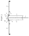
- Fig. 2
- einen auszugsweisen Querschnitt durch den Förderer einer Buchblockeinhängemaschine vor resp. im Anreibebereich der Anreibevorrichtung,
- Fig. 3
- eine Ansicht des Zugmittelgetriebes der Einrichtung und
- Fig. 4
- einen Querschnitt des Zugmittelgetriebes gemäss der Linie IV - IV in Fig. 3.
- Fig. 1
- a schematically shown rubbing device in a book block hanging machine,
- Fig. 2
- an excerpt cross-section through the conveyor of a book block hanging machine before, respectively. in the rubbing area of the rubbing device,
- Fig. 3
- a view of the traction mechanism of the device and
- Fig. 4
- a cross section of the traction mechanism according to the line IV - IV in Fig. 3rd
Die Fig. 1 zeigt eine Einrichtung 1 für das Anreiben einer
Buchdecke (nicht ersichtlich) an einen an den Aussenseiten beleimten
Buchblock, der auf einem senkrechten Abschnitt mittels
Förderer 3 auf einer Sattelplatte 4 durch den Wirkbereich einer
Anreibevorrichtung 5 transportiert wird. Der Förderer 3 weist
ein an einer Antriebswelle 6 befestigtes Antriebsrad 7 und drei
frei drehbar gelagerte Umlenkräder 8 auf, an denen ein Zugorgan
9, beispielsweise eine Kette oder Zahnriemen umläuft. Die an
dem Zugorgan 9 befestigten Sattelplatten 4 nehmen auf ihrer Bewegungsbahn
in jeder Position eine konstante Lage ein und weisen
dabei eine horizontale obere Kante 10 auf. Auf die Kante 10
der Sattelplatte 4 wird die Sattelplatte 4 von der Seite mit
einem zum Einhängen in einer Buchdecke vorbereiteten Buchblock
beschickt, der anschliessend auf der Sattelplatte 4 rittlings
aufsitzt. Hierzu werden die Buchblocks 2 mit der offenen Frontkante
nach unten gerichtet in Richtung des Pfeiles B über einen
Buchblockteiler (nicht ersichtlich), der die Buchblocks mittig
spreizt, in eine Aufnahmeposition des Förderers 3 gebracht, wo
sie von den von unten nach oben in den Buchblock 2 eintauchenden
Sattelplatten 4 übernommen werden.
Vorerst durchlaufen die an den Sattelplatten 4 aufgehängten
Buchblocks 2 einen Leimauftragsbereich (nicht dargestellt), wo
auf ihre beiden Aussenseiten durch eine Leimauftragsvorrichtung
Leim aufgetragen wird.
Bevor ein seitenbeleimter Buchblock 2 die oberhalb der Leimvorrichtung
angeordnete Anreibevorrichtung 5 resp. Anreibestation
erreicht, wird von einer Seite, senkrecht zu der nach oben gerichteten
Bewegungsbahn des Buchblocks 2, eine Buchdecke 12 zugeführt,
derart, dass sie gleichmässig verteilt auf den Buchblockrücken
14 bzw. die Sattelplatte 4 zu liegen kommt. Diese
Situation zeigt Fig. 2, wo soeben ein am Rücken gerundeter
Buchblock 2 die Ausgangsposition des Anreibens einer gerundeten
Buchdecke 12 erreicht hat. Diese liegt beidseits der Sattelplatte
4 auf einer Deckenauflage 13. Die kontinuierlich umlaufenden
Sattelplatten 4 des Förderers 3 bringen die Buchblockrücken
14 mit der Buchdecke 12 an der gerundeten Rückeneinlage
15 in Annäherung resp. in Kontakt. Darauf startet die Anreibevorrichtung
5 mit auf die gleiche Geschwindigkeit wie der Förderer
3 zunehmender Geschwindigkeit nach oben.
Der Abstand des Buchlockrückens 14 zur Rückeneinlage 15 der
Buchdecke 12 kann dabei so gewählt werden, dass der Buchblock 2
beim Start der Anreibevorrichtung mehr oder weniger in die
Buchdecke 12 eintaucht.
Darauf wird die Anreibevorrichtung 5 in die entgegengesetzte
Richtung umgesteuert, sodass die Anreibwalzen, währenddem die
Deckel 18, 19 von den Deckelauflagen 13 abgehoben und nach unten
verschwenkt werden, die Buchdecke 12 über den pilzförmigen
Aushang und die Deckel 18, 19 an den beleimten Buchblocks 2
durch Abwälzen der Anreibwalzen 16, 17 anreiben. Hierzu sind
die Abreibwalzen 16, 17 seitlich federnd abgestützt, um den
pilzförmigen Aushang schadlos überwinden zu können.
Aufgrund des variablen Schultermasses X, Abstand zwischen dem
Buchblockrücken 14 und dem durch die pilzförmige Abpressung bewirkten
Falz 21, sind die Bewegungen der Anreibevorrichtung 5
an die unterschiedlichen Querschnittsformen im Buchblockrückenbereich
anzupassen.Fig. 1 shows a device 1 for rubbing a book cover (not visible) on a book block glued on the outside, which is transported on a vertical section by means of
For the time being, the
Before a side-glued
The distance from the book block back 14 to the
The
Due to the variable shoulder dimension X, distance between the
Auch bei einem geraden Buchblock- resp. Buchrücken wird auf die gleiche Weise verfahren. Even with a straight book block or Book spine is on the proceed in the same way.
Der Antrieb der Anreibevorrichtung 5 erfolgt über ein mit der
Antriebswelle 6 des Förderers 3 verbundenes Hebelgetriebe 22.
Dieses weist gemäss Fig. 1 eine Welle 23 auf, an der ein Antriebsrad
24 des Hebelgetriebes 22 und ein eine Steuerbahn bildendes,
einen Steuerhebel 67 betätigendes rotierendes Steuerorgan
25 befestigt ist. An dem Steuerorgan 25 liegt das freie Ende
eines Hebelarmes 26 mittels Steuerrolle an, der mit einem
auf der gegenüberliegenden Seite seiner Schwenkachse 27 angeordneten
Hebelarm 28, einen Steuerhebel 67 bildend, fest verbunden
ist. An dem freien Ende des Hebelarmes 28 ist eine Verbindungsstange
29 angelenkt, die mit dem anderen Ende mit einem
Ende einer Wippe 30 verbunden ist. Gegenüberliegend an der
Schwenkachse 31 der Wippe 30 ist diese über einen Lenker 32 mit
einem Traggestell 33 der Anreibevorrichtung 5 gekuppelt. Im
Traggestell 33 sind die Anreibwalzen 16, 17 gelagert.
Antriebswelle 6 des Förderers 3 und Welle 22 des Hebelgetriebes
22 sind durch ein als "Black Box" dargestelltes Zugmittelgetriebe
34 verbunden, welches in den Fig. 3 und 4 ausführlich
dargestellt ist. Anstelle eines mühevollen Verstellens des
Steuerorgans 25 an der Welle 23 kann durch Verwendung des Zugmittelgetriebes
34 oder durch eine Servosteuerung zwischen der
Antriebswelle 6 des Förderers 3 und der Welle 23 des Hebelgetriebes
22 eine im Stillstand oder im Lauf einstellbare Drehwinkelveränderung
durchgeführt werden.
Die Antriebsverbindung zwischen Antriebswelle 6 des Förderers 3
und dem Antriebsrad 24 auf der Welle 23 erfolgt über ein Zugmittel
35, beispielsweise eine Kette oder einen Zahnriemen.
Durch die Rundung eines Buchblockrückens 2 wird beim Abpressen
die Form des pilzähnlichen Aushangs und der Abstand des Falzes
vom Buchblockrücken bestimmt bzw. die Rückenform bei der Benutzung
eines Buches beansprucht. Deshalb ist es wichtig, dass die
Bewegungen der Anreibwalzen einer Anreibevorrichtung optimal an
unterschiedliche Querschnitte im Buchrückenbereich und veränderte
Lagen des Falzes anpassbar sind.The driving of the
The
The drive connection between the
By rounding a
Die Fig. 3 und 4 zeigen eine mögliche Ausführungform eines in
die Antriebsverbindung zwischen Förderer 3 und Anreibevorrichtung
(siehe auch Fig. 1) geschalteten Zugmittelgetriebes 34.
Ein an der Antriebswelle 6 des Förderers 3 sitzendes Zahnriemenrad
7 ist antriebsseitig von dem Zugmittel 35 teilweise umschlungen
und mit einem an der Welle 23 des Hebelgetriebes 22
der Anreibevorrichtung 5 befestigten Zahnriemenrad 24 ebenso
antriebsverbunden. Die Wellen 6 und 23 teilen das Zugmittel 35
in zwei Abschnitte 36, 37, denen jeweils ein ortsfestes Rollenpaar
aus beabstandeten Umlenkrollen 38, 39 bzw. 40, 41 sowie
eine dazwischen angeordnete verstellbare Steuerrolle 42, 43 zugeordnet
sind. Zwischen den Umlenk- 38 bis 41 resp. Steuerrollen
42, 43 bilden die Abschnitte 36, 37 des Zugmittels 35 sich
gegenüberliegende offene Schlaufenabschnitte 44, 45, deren Länge
sich durch die verstellbaren Steuerrollen 42, 43 jeweils ändert.
Durch die Längenänderung der Abschnitte 36, 37 des Zugmittels
35 kann zwischen den taktgebundenen Wellen 6, 23 eine stufenlose
Phasenverschiebung vorgenommen werden, die ein optimales
Ein- und Nachstellen der Anreibwalzen 16, 17 der Anreibevorrichtung
5 an die pilzförmige Querschnittsform im Buchblockrückenbereich
auch während dem Lauf erlaubt. Anhand der Richtungspfeile
A, B in Fig. 3 erklärt, entsteht bei einer Betätigung
des Schiebers 46 durch die Gewindespindel 47 in Richtung
X+ eine Verlängerung des Zugmittelabschnitts 36 bzw. eine Verkürzung
des Zugmittelabschnitts 37, die eine Phasenverschiebung
zwischen den Drehwinkeln an der Welle 23 und der Antriebswelle
6 bewirkt. Eine Betätigung des Schiebers 46 in Gegenrichtung X-
lässt eine entgegengerichtete Phasenverschiebung zwischen Antriebswelle
6 und Welle 23 entstehen.
Eine Phasenverschiebung könnte auch mit elektrischen Wellen an
der Antriebswelle 6 und/oder Welle 23 realisiert werden, was
derzeit jedoch unwirtschaftlich zu sein scheint.
Selbstverständlich könnten bei der erfindungsgemässen Einrichtung
die Zugmittelabschnitte 36, 37 auch über den äusseren Umfangsabschnitt
der Umlenkrollen 38 bis 41 geführt werden, sodass
die durch die Steuerrollen 42, 43 gebildeten Schlaufenabschnitte
voneinander abgewandte offene Enden aufweisen, wodurch
die Steuerrollen 42, 43 näher, die Rollenpaare 38, 39; 40,
41 weiter voneinander beabstandet sind. Alle Rollen 38 bis 41
sind frei drehbar gelagert, wobei die Umlenkrollen 38 bis 41 an
einer mit dem Gestell (nicht sichtbar) der Buchblockeinhängemaschine
fest verbundenen Platte 48 und die Steuerrollen 42, 43
an einem senkrecht zu einer durch die Achsen eines Umlenkrollenpaares
38, 39 bzw. 40, 41 verlaufenden Ebene bewegbaren
Schieber 46 gelagert sind. An der von den Rollen 38 bis 41 abgewandten
Seite der Platte 48 sind an dieser zwei zu der Längsmittelachse
des Schiebers 46 beidseits angeordnete, parallele
Führungsstangen 49 befestigt, an denen der Schieber 46 bewegt
wird. Hierzu weist der Schieber 46 zwei die Platte 48 an jeweils
einer Aussparung 50 durchsetzende Lagerbüchsen 51 aufweisende
Träger 52, einen Mitnehmer 53 bildend auf, in welchen die
Gewindespindel 47 ragt, die anderenends ein mit einem Getriebemotor
54 antriebsverbundenes Kettenrad 55 aufweist. Die Gewindespindel
47 ist in einem an der Platte 48 befestigten Support
56 gelagert und der Getriebemotor 54 ist an einem mit der Platte
48 verbundenen Halter 57 befestigt. Zum Ein- bzw. Nachstellen
resp. Spannen des als Zahnriemen ausgebildeten Zugmittels
35 sind die Steuerrollen jeweils an Spannplatten 58, 59 gelagert,
die in Bewegungsrichtung des Schiebers 46 versetzbar und
arretierbar sind. Zu diesem Zweck sind die Steuerrollen 42, 43
an einem mittels Schraube 60 an der Spannplatte 58, 59 befestigten
Lagerzapfen 61 befestigt, auf welchem zur Lagerung des
Zahnriemenrades 42, 43 zwei Rillenkugellager 62 sitzen.
Das Spannen des Zahnriemens 35 erfolgt durch jeweils eine
Spannschraube 63, die kopfseitig an der in Bewegungsrichtung
inneren Stirnseite der Spannplatte 58, 59 ansteht und in einem
zwischen den Spannplatten 58, 59 an dem Schieber 46 befestigten
Balken 64 verstellbar verschraubt ist. Die Spannplatten 58, 59
weisen jeweils vier Führungsschlitze 65 auf, die von einer in
dem Schieber 46 befestigten, mit einer Unterlagsscheibe unter
dem Schraubenkopf versehenen Arretierungsschraube 66 durchsetzt
werden.3 and 4 show a possible embodiment of a traction mechanism gear 34 connected to the drive connection between the
By changing the length of the
A phase shift could also be implemented with electrical shafts on the
Of course, in the device according to the invention, the traction means
The
Im Sinne einer raumsparenden Anordnung des Zugmittelgetriebes
34 zwischen Antriebswelle 6 des Förderers 3 und der Welle 23
des Hebelgetriebes 22 für die Anreibevorrichtung 5 in einer bestehenden
Buchblockeinhängemaschine ist eine weitere ortsfeste
Umlenkrolle 68 vorgesehen.In the sense of a space-saving arrangement of the traction mechanism
34 between
Claims (12)
Priority Applications (8)
| Application Number | Priority Date | Filing Date | Title |
|---|---|---|---|
| EP99810661A EP1072436B1 (en) | 1999-07-22 | 1999-07-22 | Device for grinding the backs of book blocks in a casing-in machine |
| AT99810661T ATE253466T1 (en) | 1999-07-22 | 1999-07-22 | DEVICE FOR RUNNING A BOOK COVER ON THE Glued OUTER SURFACES OF BOOK BLOCKS TO BE HANGED IN BOOK COVERS IN A BOOK BLOCK HANGING MACHINE |
| ES99810661T ES2211019T3 (en) | 1999-07-22 | 1999-07-22 | DEVICE FOR APPLYING BY FRICTION A COVER ON THE EXCELLENT SURFACES OF BOOKED BLOCKS TO WHICH THEY SHOULD BE APPLIED COVERED IN AN APPLICATION MACHINE OF COVERS IN BOOK BLOCKS. |
| DE59907631T DE59907631D1 (en) | 1999-07-22 | 1999-07-22 | Device for rubbing a book cover on the glued outer surfaces of book blocks to be hung in book covers in a book block hanging machine |
| DK99810661T DK1072436T3 (en) | 1999-07-22 | 1999-07-22 | Device for ironing a bookbinder at the glued outer surfaces of bookblocks to be hung on a bookbinder in a bookblock hanging machine |
| US09/604,030 US6186721B1 (en) | 1999-07-22 | 2000-06-27 | Device for pressing a book cover onto the adhesive-coated outer surfaces of inner books to be inset into book covers by means of an insetting machine |
| JP2000221558A JP5048893B2 (en) | 1999-07-22 | 2000-07-21 | Device for rubbing the cover to the glued outer surface of the book block that is bound to the cover in the book block binding device |
| CNB001216619A CN1174868C (en) | 1999-07-22 | 2000-07-21 | Equipment for stitching cover of book on glued external surface of book block |
Applications Claiming Priority (1)
| Application Number | Priority Date | Filing Date | Title |
|---|---|---|---|
| EP99810661A EP1072436B1 (en) | 1999-07-22 | 1999-07-22 | Device for grinding the backs of book blocks in a casing-in machine |
Publications (2)
| Publication Number | Publication Date |
|---|---|
| EP1072436A1 true EP1072436A1 (en) | 2001-01-31 |
| EP1072436B1 EP1072436B1 (en) | 2003-11-05 |
Family
ID=8242933
Family Applications (1)
| Application Number | Title | Priority Date | Filing Date |
|---|---|---|---|
| EP99810661A Expired - Lifetime EP1072436B1 (en) | 1999-07-22 | 1999-07-22 | Device for grinding the backs of book blocks in a casing-in machine |
Country Status (8)
| Country | Link |
|---|---|
| US (1) | US6186721B1 (en) |
| EP (1) | EP1072436B1 (en) |
| JP (1) | JP5048893B2 (en) |
| CN (1) | CN1174868C (en) |
| AT (1) | ATE253466T1 (en) |
| DE (1) | DE59907631D1 (en) |
| DK (1) | DK1072436T3 (en) |
| ES (1) | ES2211019T3 (en) |
Cited By (6)
| Publication number | Priority date | Publication date | Assignee | Title |
|---|---|---|---|---|
| EP1642747A2 (en) | 2004-10-02 | 2006-04-05 | Müller Martini Holding AG | Device for grinding the back of a book |
| EP1780038A1 (en) | 2005-10-25 | 2007-05-02 | Müller Martini Holding AG | Device for grinding a book cover onto the glued back of a book block having a separate drive |
| CN100575114C (en) * | 2005-10-25 | 2009-12-30 | 米勒.马蒂尼控股公司 | To stick in the machine at bookblock and be sticked in book case the device of gluing on the bookblock surface |
| EP2287010A1 (en) | 2009-08-17 | 2011-02-23 | Müller Martini Holding AG | Method and device for connection of a book cover to glued exterior surfaces of a book block |
| EP2289706A1 (en) * | 2009-08-31 | 2011-03-02 | Hauf Handel und Service für graphische Maschinen GmbH | Pressing device |
| CN102463760A (en) * | 2010-11-11 | 2012-05-23 | 上海紫光机械有限公司 | Automatic side adhesive breaking device for adhesive binding machine |
Families Citing this family (8)
| Publication number | Priority date | Publication date | Assignee | Title |
|---|---|---|---|---|
| DE59907630D1 (en) * | 1999-07-22 | 2003-12-11 | Grapha Holding Ag | Device for gluing the outer surfaces of book blocks to be hung in a book block hanging machine in book covers |
| DE50014512D1 (en) * | 2000-03-31 | 2007-09-06 | Grapha Holding Ag | Method of attaching a cover sheet to the back of a book block formed from bound signature |
| US8333542B2 (en) * | 2001-10-24 | 2012-12-18 | Henkel Ag & Co. Kgaa | Bookbinding process |
| EP2133212B1 (en) * | 2008-06-13 | 2014-04-23 | Müller Martini Holding AG | Device for processing the back of a block hanging prominently out of a variable bracket of a book binding machine |
| EP2465697B1 (en) * | 2010-12-17 | 2015-03-25 | Müller Martini Holding AG | Method and device for producing glue-bound print products made from a block and a cover |
| CN103935152B (en) * | 2014-05-09 | 2016-01-20 | 新乡市布克包装机械有限公司 | A kind of eight book back shaped devices opening paper |
| CN109572266B (en) * | 2018-11-30 | 2020-03-24 | 重庆市骏煌印务有限公司 | Book binding device |
| CN112757804B (en) * | 2021-03-05 | 2022-09-23 | 义乌市文渊文具有限公司 | Upper bookcase device for uniform division and accompanying pressing |
Citations (1)
| Publication number | Priority date | Publication date | Assignee | Title |
|---|---|---|---|---|
| DE3713896A1 (en) * | 1986-04-26 | 1987-10-29 | Kolbus Gmbh & Co Kg | Setting device for glue application rollers in casing-in machines |
Family Cites Families (6)
| Publication number | Priority date | Publication date | Assignee | Title |
|---|---|---|---|---|
| US3469270A (en) * | 1967-10-20 | 1969-09-30 | Smyth Mfg Co | Book pressing machine with improved presser plate and conveyor mechanism and with improved dual channel arrangement |
| US3771185A (en) * | 1972-09-25 | 1973-11-13 | Kolbus A | Presser plate, conveyor mechanism and creasing iron arrangement for book pressing machine |
| US4565477A (en) * | 1981-11-16 | 1986-01-21 | Permatek, Inc. | Method of casing-in books |
| DE8507513U1 (en) | 1985-03-14 | 1985-07-18 | Vereinigte Buchbindereimaschinenfabriken GmbH, 6970 Lauda-Königshofen | Gluing device |
| JPS6169493A (en) * | 1985-07-08 | 1986-04-10 | 飯郷 昭二 | Pasting device for section facing back of cover for book |
| DE3905767A1 (en) * | 1989-02-24 | 1990-08-30 | Kolbus Gmbh & Co Kg | BOOK FORMING AND PRESSING MACHINE |
-
1999
- 1999-07-22 EP EP99810661A patent/EP1072436B1/en not_active Expired - Lifetime
- 1999-07-22 AT AT99810661T patent/ATE253466T1/en active
- 1999-07-22 DE DE59907631T patent/DE59907631D1/en not_active Expired - Lifetime
- 1999-07-22 DK DK99810661T patent/DK1072436T3/en active
- 1999-07-22 ES ES99810661T patent/ES2211019T3/en not_active Expired - Lifetime
-
2000
- 2000-06-27 US US09/604,030 patent/US6186721B1/en not_active Expired - Lifetime
- 2000-07-21 JP JP2000221558A patent/JP5048893B2/en not_active Expired - Fee Related
- 2000-07-21 CN CNB001216619A patent/CN1174868C/en not_active Expired - Fee Related
Patent Citations (1)
| Publication number | Priority date | Publication date | Assignee | Title |
|---|---|---|---|---|
| DE3713896A1 (en) * | 1986-04-26 | 1987-10-29 | Kolbus Gmbh & Co Kg | Setting device for glue application rollers in casing-in machines |
Cited By (9)
| Publication number | Priority date | Publication date | Assignee | Title |
|---|---|---|---|---|
| EP1642747A2 (en) | 2004-10-02 | 2006-04-05 | Müller Martini Holding AG | Device for grinding the back of a book |
| EP1780038A1 (en) | 2005-10-25 | 2007-05-02 | Müller Martini Holding AG | Device for grinding a book cover onto the glued back of a book block having a separate drive |
| CN100575114C (en) * | 2005-10-25 | 2009-12-30 | 米勒.马蒂尼控股公司 | To stick in the machine at bookblock and be sticked in book case the device of gluing on the bookblock surface |
| US7922436B2 (en) | 2005-10-25 | 2011-04-12 | Mueller Martini Holding Ag | Apparatus for applying adhesive to the outside surfaces of a book block to be encased in a book casing inside a casing-in machine |
| US8123450B2 (en) | 2005-10-25 | 2012-02-28 | Mueller Martini Holding Ag | Apparatus for pressing a book casing against the adhesive-coated outside surfaces of a book block to be encased in a casing-in machine |
| EP2287010A1 (en) | 2009-08-17 | 2011-02-23 | Müller Martini Holding AG | Method and device for connection of a book cover to glued exterior surfaces of a book block |
| EP2289706A1 (en) * | 2009-08-31 | 2011-03-02 | Hauf Handel und Service für graphische Maschinen GmbH | Pressing device |
| CN102463760A (en) * | 2010-11-11 | 2012-05-23 | 上海紫光机械有限公司 | Automatic side adhesive breaking device for adhesive binding machine |
| CN102463760B (en) * | 2010-11-11 | 2013-09-25 | 上海紫光机械有限公司 | Automatic side adhesive breaking device for adhesive binding machine |
Also Published As
| Publication number | Publication date |
|---|---|
| ES2211019T3 (en) | 2004-07-01 |
| DE59907631D1 (en) | 2003-12-11 |
| ATE253466T1 (en) | 2003-11-15 |
| JP2001047763A (en) | 2001-02-20 |
| CN1174868C (en) | 2004-11-10 |
| JP5048893B2 (en) | 2012-10-17 |
| EP1072436B1 (en) | 2003-11-05 |
| US6186721B1 (en) | 2001-02-13 |
| CN1281795A (en) | 2001-01-31 |
| DK1072436T3 (en) | 2004-03-15 |
Similar Documents
| Publication | Publication Date | Title |
|---|---|---|
| EP1072436B1 (en) | Device for grinding the backs of book blocks in a casing-in machine | |
| DE4116568C2 (en) | Method and device for simultaneous grinding of crank pin bearings on a crank shaft | |
| EP1780038B1 (en) | Device for grinding a book cover onto the glued back of a book block having a separate drive | |
| EP0390939A1 (en) | Vertically contour-cutting machine | |
| DE2609199A1 (en) | MACHINE FOR GRINDING EDGE AREAS OF MOLDED PARTS | |
| DE1635182A1 (en) | Clamp device for biaxial tissue stretching machine | |
| EP1708849B1 (en) | Device for finishing the steel edge of a ski | |
| DE1063570B (en) | Spreading device for the feeding device of an ironing machine | |
| EP0354515A1 (en) | Slitting or scoring machine for moving cardboard webs | |
| DE2122990C3 (en) | Machine for processing the edges of glass panes or the like. | |
| DE1777187B2 (en) | CENTERLESS GRINDING MACHINE FOR GRINDING LONG STRETCHED BARS OF DIFFERENT DIAMETERS IN A CONTINUOUS PROCESS | |
| EP0972546A2 (en) | Device and method for processing a ski or a snowboard | |
| DE2937249C2 (en) | ||
| EP1072435B1 (en) | Device for applying glue to the backs of book blocks in a casing-in machine | |
| CH423535A (en) | Ban grinding machine | |
| DE3145599C2 (en) | Leather splitting machine | |
| DE2450653A1 (en) | GRINDING MACHINE FOR SURFACE GRINDING OF THE FRONT SURFACES OF COIL SPRINGS | |
| DD206732A5 (en) | FISH PROCESSING MACHINE WITH A CONTROL DEVICE FOR THE MACHINING TOOLS | |
| DE2020835A1 (en) | Machine for the finishing of workpiece surfaces | |
| DE503554C (en) | Device for grinding and polishing facets on glass plates | |
| DE1959492B2 (en) | Device for reversing a grinding slide of a grinding machine | |
| DE3515913C1 (en) | Roller drive for a gear grinding machine | |
| DE4321450A1 (en) | Device for working the running surface and also the side edges of skis | |
| DE2421156C3 (en) | Grinding machine for chamfering the edges of a flat pane of glass | |
| DE739526C (en) | Device for bare grinding of tools |
Legal Events
| Date | Code | Title | Description |
|---|---|---|---|
| PUAI | Public reference made under article 153(3) epc to a published international application that has entered the european phase |
Free format text: ORIGINAL CODE: 0009012 |
|
| AK | Designated contracting states |
Kind code of ref document: A1 Designated state(s): AT BE CH CY DE DK ES FI FR GB GR IE IT LI LU MC NL PT SE |
|
| AX | Request for extension of the european patent |
Free format text: AL;LT;LV;MK;RO;SI |
|
| 17P | Request for examination filed |
Effective date: 20010507 |
|
| AKX | Designation fees paid |
Free format text: AT BE CH CY DE DK ES FI FR GB GR IE IT LI LU MC NL PT SE |
|
| GRAH | Despatch of communication of intention to grant a patent |
Free format text: ORIGINAL CODE: EPIDOS IGRA |
|
| GRAS | Grant fee paid |
Free format text: ORIGINAL CODE: EPIDOSNIGR3 |
|
| GRAA | (expected) grant |
Free format text: ORIGINAL CODE: 0009210 |
|
| AK | Designated contracting states |
Kind code of ref document: B1 Designated state(s): AT BE CH CY DE DK ES FI FR GB GR IE IT LI LU MC NL PT SE |
|
| PG25 | Lapsed in a contracting state [announced via postgrant information from national office to epo] |
Ref country code: IE Free format text: LAPSE BECAUSE OF FAILURE TO SUBMIT A TRANSLATION OF THE DESCRIPTION OR TO PAY THE FEE WITHIN THE PRESCRIBED TIME-LIMIT Effective date: 20031105 Ref country code: FI Free format text: LAPSE BECAUSE OF FAILURE TO SUBMIT A TRANSLATION OF THE DESCRIPTION OR TO PAY THE FEE WITHIN THE PRESCRIBED TIME-LIMIT Effective date: 20031105 Ref country code: CY Free format text: LAPSE BECAUSE OF FAILURE TO SUBMIT A TRANSLATION OF THE DESCRIPTION OR TO PAY THE FEE WITHIN THE PRESCRIBED TIME-LIMIT Effective date: 20031105 |
|
| REG | Reference to a national code |
Ref country code: GB Ref legal event code: FG4D Free format text: NOT ENGLISH |
|
| REG | Reference to a national code |
Ref country code: CH Ref legal event code: EP |
|
| REF | Corresponds to: |
Ref document number: 59907631 Country of ref document: DE Date of ref document: 20031211 Kind code of ref document: P |
|
| REG | Reference to a national code |
Ref country code: IE Ref legal event code: FG4D Free format text: GERMAN |
|
| PG25 | Lapsed in a contracting state [announced via postgrant information from national office to epo] |
Ref country code: GR Free format text: LAPSE BECAUSE OF FAILURE TO SUBMIT A TRANSLATION OF THE DESCRIPTION OR TO PAY THE FEE WITHIN THE PRESCRIBED TIME-LIMIT Effective date: 20040205 |
|
| GBT | Gb: translation of ep patent filed (gb section 77(6)(a)/1977) |
Effective date: 20040118 |
|
| REG | Reference to a national code |
Ref country code: SE Ref legal event code: TRGR |
|
| REG | Reference to a national code |
Ref country code: DK Ref legal event code: T3 |
|
| REG | Reference to a national code |
Ref country code: IE Ref legal event code: FD4D |
|
| REG | Reference to a national code |
Ref country code: ES Ref legal event code: FG2A Ref document number: 2211019 Country of ref document: ES Kind code of ref document: T3 |
|
| PG25 | Lapsed in a contracting state [announced via postgrant information from national office to epo] |
Ref country code: LU Free format text: LAPSE BECAUSE OF NON-PAYMENT OF DUE FEES Effective date: 20040722 |
|
| ET | Fr: translation filed | ||
| PG25 | Lapsed in a contracting state [announced via postgrant information from national office to epo] |
Ref country code: MC Free format text: LAPSE BECAUSE OF NON-PAYMENT OF DUE FEES Effective date: 20040731 |
|
| PLBE | No opposition filed within time limit |
Free format text: ORIGINAL CODE: 0009261 |
|
| STAA | Information on the status of an ep patent application or granted ep patent |
Free format text: STATUS: NO OPPOSITION FILED WITHIN TIME LIMIT |
|
| 26N | No opposition filed |
Effective date: 20040806 |
|
| PG25 | Lapsed in a contracting state [announced via postgrant information from national office to epo] |
Ref country code: PT Free format text: LAPSE BECAUSE OF NON-PAYMENT OF DUE FEES Effective date: 20040405 |
|
| PGFP | Annual fee paid to national office [announced via postgrant information from national office to epo] |
Ref country code: DK Payment date: 20110721 Year of fee payment: 13 |
|
| PGFP | Annual fee paid to national office [announced via postgrant information from national office to epo] |
Ref country code: GB Payment date: 20120726 Year of fee payment: 14 Ref country code: SE Payment date: 20120726 Year of fee payment: 14 |
|
| PGFP | Annual fee paid to national office [announced via postgrant information from national office to epo] |
Ref country code: DE Payment date: 20120718 Year of fee payment: 14 Ref country code: BE Payment date: 20120731 Year of fee payment: 14 Ref country code: FR Payment date: 20120808 Year of fee payment: 14 Ref country code: ES Payment date: 20120731 Year of fee payment: 14 Ref country code: IT Payment date: 20120728 Year of fee payment: 14 |
|
| PGFP | Annual fee paid to national office [announced via postgrant information from national office to epo] |
Ref country code: CH Payment date: 20121022 Year of fee payment: 14 Ref country code: NL Payment date: 20120828 Year of fee payment: 14 |
|
| PGFP | Annual fee paid to national office [announced via postgrant information from national office to epo] |
Ref country code: AT Payment date: 20120726 Year of fee payment: 14 |
|
| BERE | Be: lapsed |
Owner name: *GRAPHA-HOLDING A.G. Effective date: 20130731 |
|
| REG | Reference to a national code |
Ref country code: NL Ref legal event code: V1 Effective date: 20140201 |
|
| REG | Reference to a national code |
Ref country code: DK Ref legal event code: EBP Effective date: 20130731 |
|
| REG | Reference to a national code |
Ref country code: CH Ref legal event code: PL |
|
| REG | Reference to a national code |
Ref country code: SE Ref legal event code: EUG |
|
| REG | Reference to a national code |
Ref country code: AT Ref legal event code: MM01 Ref document number: 253466 Country of ref document: AT Kind code of ref document: T Effective date: 20130722 |
|
| GBPC | Gb: european patent ceased through non-payment of renewal fee |
Effective date: 20130722 |
|
| REG | Reference to a national code |
Ref country code: FR Ref legal event code: ST Effective date: 20140331 |
|
| PG25 | Lapsed in a contracting state [announced via postgrant information from national office to epo] |
Ref country code: DE Free format text: LAPSE BECAUSE OF NON-PAYMENT OF DUE FEES Effective date: 20140201 Ref country code: SE Free format text: LAPSE BECAUSE OF NON-PAYMENT OF DUE FEES Effective date: 20130723 Ref country code: CH Free format text: LAPSE BECAUSE OF NON-PAYMENT OF DUE FEES Effective date: 20130731 Ref country code: LI Free format text: LAPSE BECAUSE OF NON-PAYMENT OF DUE FEES Effective date: 20130731 Ref country code: NL Free format text: LAPSE BECAUSE OF NON-PAYMENT OF DUE FEES Effective date: 20140201 Ref country code: BE Free format text: LAPSE BECAUSE OF NON-PAYMENT OF DUE FEES Effective date: 20130731 Ref country code: GB Free format text: LAPSE BECAUSE OF NON-PAYMENT OF DUE FEES Effective date: 20130722 |
|
| REG | Reference to a national code |
Ref country code: DE Ref legal event code: R119 Ref document number: 59907631 Country of ref document: DE Effective date: 20140201 |
|
| PG25 | Lapsed in a contracting state [announced via postgrant information from national office to epo] |
Ref country code: AT Free format text: LAPSE BECAUSE OF NON-PAYMENT OF DUE FEES Effective date: 20130722 Ref country code: IT Free format text: LAPSE BECAUSE OF NON-PAYMENT OF DUE FEES Effective date: 20130722 Ref country code: FR Free format text: LAPSE BECAUSE OF NON-PAYMENT OF DUE FEES Effective date: 20130731 |
|
| PG25 | Lapsed in a contracting state [announced via postgrant information from national office to epo] |
Ref country code: DK Free format text: LAPSE BECAUSE OF NON-PAYMENT OF DUE FEES Effective date: 20130731 |
|
| REG | Reference to a national code |
Ref country code: ES Ref legal event code: FD2A Effective date: 20150710 |
|
| PG25 | Lapsed in a contracting state [announced via postgrant information from national office to epo] |
Ref country code: ES Free format text: LAPSE BECAUSE OF NON-PAYMENT OF DUE FEES Effective date: 20130723 |