EP1072313A2 - Vorrichtung und Verfahren zum Pipettieren von Flüssigkeiten - Google Patents
Vorrichtung und Verfahren zum Pipettieren von Flüssigkeiten Download PDFInfo
- Publication number
- EP1072313A2 EP1072313A2 EP00115591A EP00115591A EP1072313A2 EP 1072313 A2 EP1072313 A2 EP 1072313A2 EP 00115591 A EP00115591 A EP 00115591A EP 00115591 A EP00115591 A EP 00115591A EP 1072313 A2 EP1072313 A2 EP 1072313A2
- Authority
- EP
- European Patent Office
- Prior art keywords
- hose
- pipetting
- peristaltic pump
- liquid
- squeezing
- Prior art date
- Legal status (The legal status is an assumption and is not a legal conclusion. Google has not performed a legal analysis and makes no representation as to the accuracy of the status listed.)
- Withdrawn
Links
Images

Classifications
-
- B—PERFORMING OPERATIONS; TRANSPORTING
- B01—PHYSICAL OR CHEMICAL PROCESSES OR APPARATUS IN GENERAL
- B01L—CHEMICAL OR PHYSICAL LABORATORY APPARATUS FOR GENERAL USE
- B01L3/00—Containers or dishes for laboratory use, e.g. laboratory glassware; Droppers
- B01L3/02—Burettes; Pipettes
- B01L3/021—Pipettes, i.e. with only one conduit for withdrawing and redistributing liquids
-
- B—PERFORMING OPERATIONS; TRANSPORTING
- B01—PHYSICAL OR CHEMICAL PROCESSES OR APPARATUS IN GENERAL
- B01L—CHEMICAL OR PHYSICAL LABORATORY APPARATUS FOR GENERAL USE
- B01L2400/00—Moving or stopping fluids
- B01L2400/04—Moving fluids with specific forces or mechanical means
- B01L2400/0475—Moving fluids with specific forces or mechanical means specific mechanical means and fluid pressure
- B01L2400/0481—Moving fluids with specific forces or mechanical means specific mechanical means and fluid pressure squeezing of channels or chambers
-
- G—PHYSICS
- G01—MEASURING; TESTING
- G01N—INVESTIGATING OR ANALYSING MATERIALS BY DETERMINING THEIR CHEMICAL OR PHYSICAL PROPERTIES
- G01N1/00—Sampling; Preparing specimens for investigation
- G01N1/02—Devices for withdrawing samples
- G01N1/10—Devices for withdrawing samples in the liquid or fluent state
- G01N1/14—Suction devices, e.g. pumps; Ejector devices
- G01N2001/1418—Depression, aspiration
- G01N2001/1427—Positive displacement, piston, peristaltic
Definitions
- the invention relates to a device for pipetting Liquids, especially a peristaltic pump device for Pipetting liquids, and a pipetting device for parallel pipetting of a variety of liquids, Pipetting processes and applications of the peristaltic or Pipetting devices.
- Pipetting heads with 96 and more parallel pipette tips for Uptake and delivery of liquids are generally known. These work with syringes or micropipettes connected in parallel, with which the liquids to be pipetted are sucked in and be delivered again.
- Such pipetting heads are because of the necessary high number of precision syringes expensive and because of their size and weight as movable Pipetting stations in automated systems only limited suitable. The cleaning of the syringes or pipettes between pipetting different and possibly also incompatible samples is time consuming.
- the object of the invention is to provide improved pumping and pipetting devices to create the disadvantages of conventional Pipetting devices can be avoided and the in particular have a simple structure, a precise one Allow liquid dosing in a large volume range and can be integrated into automated systems.
- the task the invention is also to provide improved pipetting methods and applications of the pipetting devices.
- a Peristaltic pump device with at least one on a fixed one Support running hose and a squeezing device provided that the hose depends on the operating state squeeze together at at least one clamping position or also can release, the squeeze device for a linear Reverse movement (movement with reversal of direction) between two spaced apart hose sections, preferably between the two hose ends, and / or between one attached and a lifted state is designed. It will use a new single or multiple linear hose pump a squeezing device (squeezing roller or bar) created, the for forward-backward operation between different Clamping positions and / or for squeezing or Release at least one hose at a clamping position is designed.
- the pipetting volume formed by at least one elastic hose.
- the pipetting volume can be enlarged or reduced.
- the hose pump device according to the invention preferably has a variety of hoses that are together on one Pad arranged and with the squeezing device can be operated simultaneously. With straight and parallel alignment of the hoses on the support and precise control the movement of the squeezing device are advantageously identical liquid volumes were added to all tubes or delivered. The reproducibility at the parallel Processing of liquid samples is considerable despite this simplified construction as good as with the conventional syringe arrangements.
- a preferred embodiment of the invention forms the peristaltic pump device of the type mentioned above Pipetting device for parallel pipetting of a large number small amounts of liquid.
- the pipetting device is preferred as a pipetting head in automated laboratory systems, e.g. B. for genetic engineering or biochemical applications.
- the pipetting head preferably contains a combination the peristaltic pump device (precision peristaltic pump pipettor) for amounts between 1 and z. B. 100 ul with a Suction-pressure conveyor system (suction-pressure pipettor) for larger ones Quantities in the milliliter range.
- the liquid intake takes place in the microliter range, preferably by peristaltic pump suction.
- the volume is measured by the squeezer (Squeeze roller) covered distance or distance the clamping positions at the beginning or end of the suction movement.
- the delivery of the sucked up and stored in the tips Liquids at the target sites can either pass through inverse peristaltic pump feed or after lifting the pinch roller by the action of a slight excess air pressure a combined air / liquid container (combination container or combination boiler). In the latter case it works the peristaltic pump device as a multi-valve.
- the peristaltic pump device is particularly advantageous as Multi or multiple valve can be used when the squeeze device both in the level of the support between the clamping positions moved as well as from the attached, clamped state can be lifted off the edition in a released condition is.
- the multi-valve operation enables effective flushing the pipette tips with sufficiently large volumes of cleaning liquids and a quick and drop-free delivery small amounts of liquid from the pipette tips.
- For pipetting becomes a suction effect by acting on the ends of the hoses with a negative pressure and formation of the negative pressure inside the hose by releasing the squeezing device achieved. Conversely, by applying a Overpressure the absorbed liquid can be released.
- a hose system is for at least 10, preferably more designed as 20 hoses and z. B. with 24 working in parallel Pipette tips especially for the processing of 24 wells and 96-well microtiter plates.
- the integrated hose cleaning system draws its cleaning fluid from the combi boiler, which is controlled by a Swiveling movement of either air or liquid into the pump tubing enters.
- the manually replaceable standard pipette tips can also by syringing in peristaltic pump mode getting cleaned.
- the combi boiler For aspirating or entering larger amounts of reagent in the milliliter range the combi boiler from which in this case the cleaning liquid normally located there is suctioned off and -when an input of liquid this should be done - replaced by an appropriate reagent becomes.
- a corresponding negative pressure (Suction) or overpressure is the squeeze roller for a defined Time raised, so corresponding larger quantities of liquid from the pipetting positions in the combination kettle or transported from the combination kettle to the pipetting positions become.
- the volume is measured by Amount of suction or pressure applied and the take-off time of the Squeeze roller from the hoses.
- the invention also relates to a pipetting method which a liquid sample from a source container with a A tube with a negative pressure in a pipette tip recorded, transported to a target container and is dispensed there from the pipette tip.
- the inclusion of the Liquid in the pipette tip is made by forming a Vacuum inside the hose by first pulling the hose adjacent to the pipette tip at a first clamping position squeezed together with a squeezing device and then the squeezer is moved so that the Clamping position removed from the pipette tip.
- the relaxing one Hose material expands to the shape of the hose and forms a cavity with a negative pressure relative to the environment.
- the size of the pipetting volume is determined by the Hose volume between the initial clamp position and determined a clamping position at which the movement of the squeezing device is stopped.
- the liquid is dispensed vice versa by squeezing out the liquid with the Squeezing device or with an external suction-pressure conveyor system, the one possibly opposite to the pipette tip End of the hose is coupled.
- the pipette tip can also be inserted through a free hose end or an attached cannula can be formed.
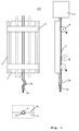
- Fig. 1 is the structure of the main components of an inventive Peristaltic pump device illustrated.
- the Peristaltic pump device can be pulled through with a hose ( shown) or several hoses (dashed for example shown) can be realized. Details and Variations in the attachment of the hose, the actuation the squeezer and use in a pipetting head are illustrated in Fig. 2.
- Fig. 2 it is emphasized that the application of the peristaltic pump device according to the invention not for use in a multiple multipipetting head is limited.
- Subject of the invention is also a single, for example hand-operated pipette with a hose pump device according to the invention.
- In the 1 and 2 designate the same reference numerals accordingly Components.
- a hose pump device 100 comprises at least one arranged on a fixed support 3 Hose 2 and a squeezing device 5, 6.
- the support 3 is for example a flat plate in which at least one groove-shaped recess 3a for receiving the at least one Hose 2 runs (see insert in Fig. 1, bottom left).
- the depression preferably has a cross section that is sufficient Space for receiving the deformed hose forms.
- the depth depends on the geometry of the hose and on of, if applicable, provided on the edition side scroll bars selected so that when attached Squeezing device a secure closing of the hose is guaranteed at the respective clamping position.
- the deepening is less than or equal to half, for example Hose diameter.
- the formation of the recess 3a is not a mandatory feature the invention.
- depressions are dispensed with.
- the hoses are then on the flat surface of the support side by side.
- the attachment the hoses can be glued on, for example the support or by means of a cross bar, which the hoses in in an applied, uncompressed state.
- spacers can also be used instead of the recess 3a be provided, generally designed to do so are, the reverse movement along the pad 3 with such Distance from the edition 3 that the Hoses are only clamped together as much as it is for one tight closure is required.
- the spacer also on the squeeze roller in the form of side collar be formed.
- the side collar on the The ends of the squeeze roller have a larger diameter than the middle area squeezing the tubes the pinch roller.
- the collars run along the side of the hoses on the edition 3. It can also be the frame 5 with a appropriate limiter to maintain the distance of the squeeze roller be equipped by the edition 3.
- the hoses on the support or in the recesses with an axially aligned Voltage are attached. Through tensioned attachment the inner volume of the hose can be varied. By the The pipetting volumes can be adjusted by several Hoses are made on a support.
- a pipette tip 2a is attached, via which the liquid in the hose is sucked in.
- the compensation piece 2b can be different Have functions. With small pipette tips or when operating without a pipette tip, the compensation piece 2b a dead volume into which the liquid to be pipetted is sucked becomes. This prevents the liquid from entering the actual pipetting volume of the tube on the support reached. Furthermore, the compensation piece 2b is used for length compensation for pipetting heads with a large number of parallel actuated pipettes (see Fig. 2).
- the equalizing pieces must provide the same pipetting volume 2b be the same length for all pipetting tips, even if in the pipetting head between the pipetting tips and of the support, depending on the design, different distances given are.
- the compensating piece 2b is preferred formed integrally with the hose 2, it can in particular omitted in single pipette applications.
- the hose is open depending on the application (see Fig. 1, left view) or with a suction-pressure conveyor system 13 connected (see Fig. 1, right view, Fig. 2).
- the squeezing device comprises a running squeezing roller 6, which on a suspension and operating frame 5 (in the right view of Fig. 1 not shown) is attached.
- the pinch roller 6 can with the frame 5 between different Positions are moved, which are exemplary in the right View of Fig. 1 are shown. I'm on the surface 3b of the pad 3 can be placed on the squeeze roller 6 between a front clamping position A and a rear clamping position B and moved according to all intermediate positions become. Due to the distance from the front clamping position A the pipetting volume in tube 2 is determined.
- the squeeze roller can also be moved from the hose to a release position be lifted off so that this relaxes, as exemplified at position C is illustrated.
- the pinch roller 6 (or Ledge) extends perpendicular to the longitudinal extension of one or of several tubes 2 over a width, all of them Covering hoses.
- the pad 3 can generally itself functions of the frame 5th take.
- the pad 3 is equipped with spacers that ensure that the hose does not hurt when squeezed together becomes. As a spacer, it can be attached to the groove or depression 3a adjacent surface 3b of the support 3 be used. But it is also possible on the sides of the Place pad 3 and / or catwalks between the tubes, on the support 3 in the longitudinal direction of the hoses extend and on which the pinch roller 6 (or bar) the squeezing device rests in the attached state.
- the hose 2 consists for example of silicone rubber and has an outside diameter of 3 mm and an inside diameter of 1 mm.
- the pipetting volume between the clamp positions A and B is, for example, 60 ⁇ l.
- the squeeze roller 6 is operated with a precise stepper motor, so that Liquid volumes in the range from 1 to 60 ⁇ l can be dosed.
- the pad 3 and the squeeze roller 6 are, for example made of plastic or metal.
- the diameter of the squeeze roller 6 is, for example, around 10 to 15 mm.
- Fig. 2 is the basic structure of a 24-fold multipipetting head shown with the advantageously both 24-well microtiter plates as well as 4 nested Accesses 96-well microtiter plates can be processed. It is particularly advantageous that it also implements 96-well plates can be made in 4x24-well plates. The principle is not applied to 24 parallel channels limited. By equipping the head with more removal tips and hoses possibly in a multi-level arrangement significantly more samples can be processed in parallel.
- the pipetting tips 2a arranged in a 4 x 6 array are attached to the plate 1, which is fixed to the base plate 3 (Edition 3) is connected.
- you can cannulas made of plastic or stainless steel tubing can also be used.
- the use of commercially available pipette tips is but advantageous because they can be easily replaced can have good properties without additional development work ensure when dispensing liquid in the target area.
- Silicone tubes 2 lead from the pipette tips more identically Shape and size on the base plate 3 in the combination container 13. For small pipette volume differences between the It is important to tip that the pump tubing from a uniform Manufacturing batch originate.
- the hoses 2 run on the base plate 3 in an absolutely flat recess of about half a hose diameter or they run side by side lying on the surface of the base plate 3.
- a pressure roller 6 (or squeeze roller 6) is in the frame 5 attached, which is rotatably suspended in the bearing 10. Will the Pneumatic cylinder 7 actuated, then he presses the pressure roller 6 over the bracket 8 on the hoses and closes them Squeezing or pinching similar to the function of a conventional rotary peristaltic pump.
- the role 6 with The bracket and the pressure cylinder 7 are on the slide 9 attached, the linear stepper motor 11 from the drawn Position can be moved up and back about 6 cm can. This stroke determines the amount of fluid that sucked into the pipette tips when the pressure roller is pressed on can be.
- the fluid release can be done by reverse Direction of rotation of the stepper motor moves the pressure roller down become.
- the combination container 13 can either only contain compressed air or compressed air and a certain amount of liquid for flushing purposes or a reagent for pipetting into samples. He is in a bearing 16 is pivotally mounted and can be used in pipetting with an air pressure adapted to the application be provided. The hose ends are near the bearing 16 introduced into the combination container 13. The combination container is located 13 in the drawn base position, then collects the liquid on the lower lying away from the bearing 16 Side of the combination container and gives the hose ends for the compressed air free. By activating the pneumatic cylinder 15, the combination container 13 is tilted around the bearing 16, the Liquid runs to the left side of the boiler and covers it the hose ends. The built-in partition with Through openings on the floor prevent violent spilling the liquid in the area of the hose ends.
- the system can also be used to draw off large quantities of liquid be used.
- the pressure roller 6 also be lifted off the hoses.
- the pipetting head is an independent unit, which over the Plate 20 attached to any z, x-z or x-y-z travel system can be.
- the operational supply includes the stepper motor control, two air pressure control lines and the air or Liquid supply lines for the combination boiler.
- the pneumatic drives 7 and 15 can also be by hydraulic or electric drives can be replaced.
- the multipipetting head can be used in a variety of ways, such as is explained below by way of example.
- the hose pump system can be completely independent of the suction / pressure system can be used as pipettors.
- the combination container 13 is not used here and can be designed accordingly Pipetting heads are omitted.
- the pinch roller (Pinch roller) remains by activating the pneumatic cylinder 7 always pressed onto the hoses or the catwalks 4.
- the pipette tips are in the liquid of the Swelling samples immersed, the slide 9 is activated of the linear motor 11 moves upwards until the pipetted Quantity is sucked into the tips 2a. This amount is measured according to the inner tube diameter and the length of the hub.
- the one in the top 2a Liquid through an opposite movement of the sled 9 downwards and correspondingly unrolling the pressure roller 6 down again from the tips.
- An inside cleaning the tip must be sucked in in this operating mode and ejecting flushing liquid by opening and closing the Pressure roller take place.
- An external rinsing of the tips can always by immersing the tips one or more times in Rins
- the efficiency of the system can be increased significantly if the liquid sucked into the tips at the destination by applying gentle air pressure from the combination container blows out.
- the combination container in the base position in which only has compressed air on the hose ends, permanently under set a slight excess pressure of, for example, 10 to approx. 30 mbar.
- the existing one prepares low blow-out pressure in the combination container and thus in the hoses no problems above the pinch roller.
- the blow-out pressure is switched into the pipette tips and blows the liquid in no time without Drop formation in the target container. Before adding new ones The slide 9 must move samples back into the suction position become. This can happen during the procedure for the new source position respectively.
- This combined operating mode is also advantageous because the pump hoses after lifting the pinch roller of displacements caused by the rolling of the roller on the Tubes can arise, relax again. Also internal cleaning can be essential using the combi boiler be accelerated. This requires cleaning liquid in the right part of the kettle and the pipetting head be positioned above a cleaning station, in which catches the liquid emerging from the tips and, if necessary, also an external cleaning of the tips can be. During the boiler (combination container) for blowing out remains in the basic position, he must for the interior cleaning can be tilted so that the Hose ends are flooded and then the cleaning liquid after lifting the pinch roller hydrostatic and from Overpressure is pressed through the hoses.
- the length of the lift-off time the pinch roller determines together with the pressure in the Combination container the amount of flushing liquid flowing through the hose. It is advantageous to finish the flush first the pressure roller with flooded hose ends in the combination container close again, then tip the combination container back and then the pinch roller for blowing air through the tubes and pipette tips again for a certain Time to open. This prevents sloshing the liquid has uneven air bubbles in the hoses are introduced that lead to different flow resistances and thus to uneven flow of detergent run the hoses.
- a useful application of this principle is e.g. the media exchange in cell cultures in microtiter plates. To do this, you must first the previous medium can be suctioned off from the cultures and then new medium is applied. For vacuuming the previous medium is in the basic position via the connection 17 Suction applied to the combi boiler.
- the pipette tips dipping into the wells are followed by Open the pressure roller 6 the previous medium in the boiler sucked in.
- the liquid collects through the inclined position right over the suction nozzle 19, via which they finally is also eliminated.
- the new medium is over the nozzle 18 poured into the kettle, pressurized and after tipping of the boiler and opening of the pressure roller in the wells.
Landscapes
- Health & Medical Sciences (AREA)
- Clinical Laboratory Science (AREA)
- Chemical & Material Sciences (AREA)
- Chemical Kinetics & Catalysis (AREA)
- Sampling And Sample Adjustment (AREA)
- Automatic Analysis And Handling Materials Therefor (AREA)
- Reciprocating Pumps (AREA)
Abstract
Description
- Fig. 1:
- schematische Drauf- und Seitenansichten einer erfindungsgemäßen Schlauchpumpeneinrichtung, und
- Fig. 2:
- schematische Drauf- und Seitenansichten einer erfindungsgemäßen Pipettiereinrichtung.
- 1
- Pipettierplatte mit den als 4 x 6 Array angeordneten Pipettenspitzen
- 2
- Silikon-Pumpenschläuche
- 2a
- Pipettenspitze
- 2b
- Ausgleichsstück
- 3
- Auflage (oder Grundplatte) der Linear-Schlauchpumpe
- 3a
- Vertiefung
- 3b
- Oberfläche der Auflage 3
- 4
- Laufstege zum Abrollen der Abquetschrolle 6
- 5
- Aufhängungs-und Betätigungsrahmen für die Abquetschrolle 6
- 6
- Abquetschrolle der Schlauchpumpe
- 7
- Pneumatik-Anpreßzylinder für die Abquetschrolle
- 8
- Betätigungsbügel, auf den der Pneumatik-Anpreßzylinder 7 wirkt
- 9
- Verfahrschlitten
- 10
- Drehlager für den Rahmen der Andruckrolle
- 11
- Linear-Schrittmotor
- 12
- Spindel des Linear-Schrittmotors
- 13
- Kombibehälter für Druck-/Sogluft, Reinigungsflüssigkeit oder Reagenzien
- 14
- Halterahmen für den Kippbehälter und pneumatische Betätigung
- 15
- Pneumatikzylinder zum Kippen des Kombikessels
- 16
- Befestigung und Drehlager des Kombikessels
- 17
- Luftanschluß des Kombikessels (Sog und Druck)
- 18
- Anschluß für Flüssigkeitszufuhr in den Kombikessel
- 19
- Anschluß für Flüssigkeitsabsaugung aus dem Kombikessel
- 20
- Befestigungsplatte für den Pipettierkopf am Schlitten eines x-y-z-Verfahrsystems
Claims (19)
- Schlauchpumpeneinrichtung (100) mit mindestens einem auf einer festen Auflage (3) angeordneten Schlauch (2) und einer Abquetscheinrichtung (5,6), die in einem auf die Auflage (3) aufgesetzten Zustand den Schlauch (2) an mindestens einer Klemmposition (A,B) entlang seiner Länge zusammenquetscht und die relativ zur Auflage (3) beweglich ist,
dadurch gekennzeichnet, dass
die Abquetscheinrichtung (5,6) für eine lineare Umkehrbewegung zwischen zwei voneinander beabstandeten Klemmpositionen (A,B) und/oder zwischen einer Klemmposition und einer Freigabeposition (C) eingerichtet ist. - Schlauchpumpeneinrichtung gemäß Anspruch 1, bei der die Auflage (3) mit einem Abstandshalter (3a,4) ausgestattet ist, der einen Anschlag zur Begrenzung des Zusammenquetschens des Schlauches bildet.
- Schlauchpumpeneinrichtung gemäß Anspruch 2, bei der der Abstandshalter durch eine Nut (3a) in der Auflage (3), wobei der Schlauch (2) in der Nut (3a) teilweise versenkt angeordnet ist, oder durch mindestens zwei seitlich am Schlauch verlaufende Laufstege (4) gebildet wird, über die der Schlauch teilweise hinausragt.
- Schlauchpumpeneinrichtung gemäß einem der vorhergehenden Ansprüche, bei der die Abquetscheinrichtung durch eine laufende Abquetschrolle oder eine verschiebbare Leiste gebildet wird, die jeweils mit einer Antriebseinrichtung (5) zwischen den Schlauchabschnitten verstellbar sind.
- Schlauchpumpeneinrichtung gemäß einem der vorhergehenden Ansprüche, bei der eine Vielzahl von Schläuchen auf der Auflage (3) angeordnet sind und die Abquetscheinrichtung dazu eingerichtet ist, im auf die Auflage (3) aufgesetzten Zustand alle Schläuche gleichzeitig zusammenzuquetschen.
- Schlauchpumpeneinrichtung gemäß einem der vorhergehenden Ansprüche, bei der der Abrollweg der Abquetscheinrichtung (5,6) auf der Auflage (3) geradlinig oder gekrümmt ist.
- Schlauchpumpeneinrichtung gemäß einem der vorhergehenden Ansprüche, bei der an einem ersten Ende des mindestens einen Schlauches eine Pipettenspitze (2a) vorgesehen ist und ein zweites, entgegengesetztes Ende des Schlauches eine freie Öffnung bildet oder mit einem Vorratsbehälter (13) verbunden oder an einem Saug-Druck-Fördersystem angeschlossen ist.
- Schlauchpumpeneinrichtung gemäß einem der vorhergehenden Ansprüche, bei der die Abquetscheinrichtung (5,6) von der Auflage (3) in die Freigabeposition (C) abhebbar angeordnet ist, wobei der mindestens eine Schlauch (2) im abgehobenen Zustand der Abquetscheinrichtung (5,6) einen entspannten Zustand einnimmt.
- Schlauchpumpeneinrichtung gemäß Anspruch 8, die eine Mehrfachventileinrichtung bildet.
- Pipettiereinrichtung, die mit einer Schlauchpumpeneinrichtung gemäß einem der Ansprüche 1 bis 9 ausgestattet ist.
- Pipettiereinrichtung gemäß Anspruch 10, bei der die Schlauchpumpeneinrichtung mit einer Vielzahl von Schläuchen versehen ist, an deren Enden sich jeweils eine Pipettenspitze (2a) befindet, wobei die Pipettenspitzen matrixartig in geraden Reihen und/oder Spalten angeordnet sind.
- Pipettiereinrichtung gemäß Anspruch 10 oder 11, bei der mehrere Schlauchpumpeneinrichtungen jeweils mit einer Vielzahl von Schläuchen einen Aufbau mit mehreren Abquetschebenen bilden.
- Pipettiereinrichtung gemäß Ansprüche 10 bis 12, bei der alle Schläuche mit einem Kombinationsbehälter (13) zur Aufnahme eines unter Unter- oder Überdruck stehenden Gases oder einer Flüssigkeit verbunden sind.
- Pipettiereinrichtung gemäß Anspruch 13, bei der der Kombinationsbehälter verschwenkbar angeordnet ist.
- Pipettiereinrichtung gemäß Anspruch 13 oder 14, bei der der Kombinationsbehälter mit einem Saug-Druck-Fördersystem verbunden ist.
- Pipettierverfahren, bei dem eine Flüssigkeitsprobe von einem Quellbehälter in eine Pipettenspitze (2a) und/oder ein Ausgleichsstück (2b) mindestens eines Schlauches (2) aufgenommen wird, indem im Schlauch (2) mit einer Abquetscheinrichtung (5,6) ein Unterdruck erzeugt wird, die von einer Klemmposition (A) nahe der Pipettenspitze (2a) oder dem Ausgleichsstück (2b) zu einer entfernten Klemmposition (B) bewegt wird, und bei dem die Flüssigkeit zu einem Zielbehälter bewegt wird.
- Pipettierverfahren gemäß Anspruch 16, bei dem die Abgabe der Flüssigkeit in den Zielbehälter durch eine umgekehrte Bewegung zwischen den Klemmpositionen erfolgt.
- Pipettierverfahren gemäß Anspruch 16, bei dem die Abgabe der Flüssigkeit in den Zielbehälter durch Ausübung eines Überdrucks erfolgt, der an das zur Pipettenspitze (2a) oder das Ausgleichsstück (2b) entgegengesetzte Ende des Schlauches (2) angelegt wird, wobei der Überdruck durch Freigabe des mindestens einen Schlauches durch Abheben der Abquetscheinrichtung in eine Freigabeposition (C) ausgeübt wird.
- Verwendung einer Vorrichtung oder eines Verfahrens gemäß einem der folgenden Ansprüche zum Pipettieren von Flüssigkeiten, zum Flüssigkeitswechsel an Mikrotiterplatten und/oder zum Durchmischen von Flüssigkeiten.
Applications Claiming Priority (2)
| Application Number | Priority Date | Filing Date | Title |
|---|---|---|---|
| DE19934896 | 1999-07-24 | ||
| DE1999134896 DE19934896A1 (de) | 1999-07-24 | 1999-07-24 | Pipettierkopf für Parallelpipettierer |
Publications (2)
| Publication Number | Publication Date |
|---|---|
| EP1072313A2 true EP1072313A2 (de) | 2001-01-31 |
| EP1072313A3 EP1072313A3 (de) | 2002-09-11 |
Family
ID=7916009
Family Applications (1)
| Application Number | Title | Priority Date | Filing Date |
|---|---|---|---|
| EP00115591A Withdrawn EP1072313A3 (de) | 1999-07-24 | 2000-07-19 | Vorrichtung und Verfahren zum Pipettieren von Flüssigkeiten |
Country Status (2)
| Country | Link |
|---|---|
| EP (1) | EP1072313A3 (de) |
| DE (1) | DE19934896A1 (de) |
Cited By (1)
| Publication number | Priority date | Publication date | Assignee | Title |
|---|---|---|---|---|
| WO2006076957A1 (de) * | 2005-01-19 | 2006-07-27 | Zengerle, Roland | Pipettenspitze, pipetiervorrichtung, pipettenspitzenbetätigungsvorrichtung und verfahren zum pipetieren im nl-bereich |
Family Cites Families (5)
| Publication number | Priority date | Publication date | Assignee | Title |
|---|---|---|---|---|
| FR1527784A (fr) * | 1967-01-10 | 1968-06-07 | Ceskoslovenska Akademie Ved | Procédé et dispositif pour la circulation des liquides dans des flexibles minces |
| US4195526A (en) * | 1978-02-09 | 1980-04-01 | Corning Glass Works | Hand-held pipetter |
| JPH06102151A (ja) * | 1992-09-18 | 1994-04-15 | Mitsubishi Yuka B C L:Kk | 分注装置 |
| ATE259068T1 (de) * | 1996-05-31 | 2004-02-15 | Packard Instrument Co Inc | Vorrichtung zur handhabung von mikroflüssigkeitsmengen |
| US5915284A (en) * | 1996-07-22 | 1999-06-22 | Cyberlab, Inc. | Multiple channel pipetting device |
-
1999
- 1999-07-24 DE DE1999134896 patent/DE19934896A1/de not_active Withdrawn
-
2000
- 2000-07-19 EP EP00115591A patent/EP1072313A3/de not_active Withdrawn
Cited By (2)
| Publication number | Priority date | Publication date | Assignee | Title |
|---|---|---|---|---|
| WO2006076957A1 (de) * | 2005-01-19 | 2006-07-27 | Zengerle, Roland | Pipettenspitze, pipetiervorrichtung, pipettenspitzenbetätigungsvorrichtung und verfahren zum pipetieren im nl-bereich |
| US8071049B2 (en) | 2005-01-19 | 2011-12-06 | Roland Zengerle | Pipette tip, pipetting device, pipette tip actuating device and method for pipetting in the NL range |
Also Published As
| Publication number | Publication date |
|---|---|
| EP1072313A3 (de) | 2002-09-11 |
| DE19934896A1 (de) | 2001-01-25 |
Similar Documents
| Publication | Publication Date | Title |
|---|---|---|
| DE60013983T2 (de) | Mehrkanal-Pipettensystem und Pipettenspitzen dafür | |
| DE2557961C3 (de) | Flüssigkeitspumpsystem für einen Flüssigkeitsstrahlschreiber | |
| DE2638659C2 (de) | Mit der Hand zu haltende Pumppipette | |
| DE69835691T2 (de) | Vielkanal-pipettiergerät | |
| DE2911443C2 (de) | Druckmittelbetätigte Pumpe mit veränderbarem Fördervolumen | |
| EP3680016B1 (de) | Pipette für den gebrauch mit einer pipettenspitze | |
| EP1699560B1 (de) | Pipettenspitze, pipetiervorrichtung, pipettenspitzenbetätigungsvorrichtung und verfahren zum pipetieren im nl-bereich | |
| EP1598113B1 (de) | Pipette | |
| DE2505431A1 (de) | Pipette | |
| DE2640491A1 (de) | Automatischer pipettierapparat | |
| DE102010038414A1 (de) | Pipettiervorrichtung mit Drosselstelle im Pipettierkanal | |
| DE102013106534B4 (de) | Chromatographiepipettenspitze | |
| EP1905469A1 (de) | Mikrodosiervorrichtung für ein flüssiges Medium | |
| DD232528A5 (de) | Peristaltische pumpe | |
| DE60127433T2 (de) | Pipettiervorrichtung mit spülung | |
| DE2412635C3 (de) | ||
| DE3786519T2 (de) | Probeentnahmevorrichtung mit Mehrkanalpipette. | |
| DE2412635B2 (de) | Vorrichtung zur probenentnahme | |
| EP2623203B1 (de) | Kapillardispenser | |
| DE1941481B2 (de) | ||
| WO2000049418A1 (de) | Dosiervorrichtung sowie verfahren zum betreiben einer dosiervorrichtung | |
| EP3260822A1 (de) | Mehrkanalspritze für den gebrauch mit einer dosiervorrichtung | |
| DE2132066A1 (de) | Pipettiervorrichtung, zugehoerige pipetten und verfahren zum pipettieren | |
| DE2415021C3 (de) | Mikropipettiereinrichtung | |
| DE10049507B4 (de) | Pipette |
Legal Events
| Date | Code | Title | Description |
|---|---|---|---|
| PUAI | Public reference made under article 153(3) epc to a published international application that has entered the european phase |
Free format text: ORIGINAL CODE: 0009012 |
|
| AK | Designated contracting states |
Kind code of ref document: A2 Designated state(s): AT BE CH CY DE DK ES FI FR GB GR IE IT LI LU MC NL PT SE |
|
| AX | Request for extension of the european patent |
Free format text: AL;LT;LV;MK;RO;SI |
|
| PUAL | Search report despatched |
Free format text: ORIGINAL CODE: 0009013 |
|
| AK | Designated contracting states |
Kind code of ref document: A3 Designated state(s): AT BE CH CY DE DK ES FI FR GB GR IE IT LI LU MC NL PT SE |
|
| AX | Request for extension of the european patent |
Free format text: AL;LT;LV;MK;RO;SI |
|
| 17P | Request for examination filed |
Effective date: 20030310 |
|
| AKX | Designation fees paid |
Designated state(s): CH DE GB LI |
|
| STAA | Information on the status of an ep patent application or granted ep patent |
Free format text: STATUS: THE APPLICATION IS DEEMED TO BE WITHDRAWN |
|
| 18D | Application deemed to be withdrawn |
Effective date: 20050201 |