EP1071152A1 - Method for arranging elliptic cylindrical cell and assembled battery - Google Patents
Method for arranging elliptic cylindrical cell and assembled batteryInfo
- Publication number
- EP1071152A1 EP1071152A1 EP20000115754 EP00115754A EP1071152A1 EP 1071152 A1 EP1071152 A1 EP 1071152A1 EP 20000115754 EP20000115754 EP 20000115754 EP 00115754 A EP00115754 A EP 00115754A EP 1071152 A1 EP1071152 A1 EP 1071152A1
- Authority
- EP
- European Patent Office
- Prior art keywords
- cells
- cylindrical shape
- elliptic cylindrical
- disposed
- wall
- Prior art date
- Legal status (The legal status is an assumption and is not a legal conclusion. Google has not performed a legal analysis and makes no representation as to the accuracy of the status listed.)
- Withdrawn
Links
Images


Classifications
-
- H—ELECTRICITY
- H01—ELECTRIC ELEMENTS
- H01M—PROCESSES OR MEANS, e.g. BATTERIES, FOR THE DIRECT CONVERSION OF CHEMICAL ENERGY INTO ELECTRICAL ENERGY
- H01M6/00—Primary cells; Manufacture thereof
- H01M6/04—Cells with aqueous electrolyte
- H01M6/06—Dry cells, i.e. cells wherein the electrolyte is rendered non-fluid
- H01M6/10—Dry cells, i.e. cells wherein the electrolyte is rendered non-fluid with wound or folded electrodes
-
- H—ELECTRICITY
- H01—ELECTRIC ELEMENTS
- H01M—PROCESSES OR MEANS, e.g. BATTERIES, FOR THE DIRECT CONVERSION OF CHEMICAL ENERGY INTO ELECTRICAL ENERGY
- H01M10/00—Secondary cells; Manufacture thereof
- H01M10/05—Accumulators with non-aqueous electrolyte
- H01M10/058—Construction or manufacture
-
- H—ELECTRICITY
- H01—ELECTRIC ELEMENTS
- H01M—PROCESSES OR MEANS, e.g. BATTERIES, FOR THE DIRECT CONVERSION OF CHEMICAL ENERGY INTO ELECTRICAL ENERGY
- H01M10/00—Secondary cells; Manufacture thereof
- H01M10/60—Heating or cooling; Temperature control
- H01M10/61—Types of temperature control
- H01M10/613—Cooling or keeping cold
-
- H—ELECTRICITY
- H01—ELECTRIC ELEMENTS
- H01M—PROCESSES OR MEANS, e.g. BATTERIES, FOR THE DIRECT CONVERSION OF CHEMICAL ENERGY INTO ELECTRICAL ENERGY
- H01M10/00—Secondary cells; Manufacture thereof
- H01M10/60—Heating or cooling; Temperature control
- H01M10/62—Heating or cooling; Temperature control specially adapted for specific applications
- H01M10/625—Vehicles
-
- H—ELECTRICITY
- H01—ELECTRIC ELEMENTS
- H01M—PROCESSES OR MEANS, e.g. BATTERIES, FOR THE DIRECT CONVERSION OF CHEMICAL ENERGY INTO ELECTRICAL ENERGY
- H01M10/00—Secondary cells; Manufacture thereof
- H01M10/60—Heating or cooling; Temperature control
- H01M10/64—Heating or cooling; Temperature control characterised by the shape of the cells
- H01M10/647—Prismatic or flat cells, e.g. pouch cells
-
- H—ELECTRICITY
- H01—ELECTRIC ELEMENTS
- H01M—PROCESSES OR MEANS, e.g. BATTERIES, FOR THE DIRECT CONVERSION OF CHEMICAL ENERGY INTO ELECTRICAL ENERGY
- H01M10/00—Secondary cells; Manufacture thereof
- H01M10/60—Heating or cooling; Temperature control
- H01M10/65—Means for temperature control structurally associated with the cells
- H01M10/651—Means for temperature control structurally associated with the cells characterised by parameters specified by a numeric value or mathematical formula, e.g. ratios, sizes or concentrations
-
- H—ELECTRICITY
- H01—ELECTRIC ELEMENTS
- H01M—PROCESSES OR MEANS, e.g. BATTERIES, FOR THE DIRECT CONVERSION OF CHEMICAL ENERGY INTO ELECTRICAL ENERGY
- H01M10/00—Secondary cells; Manufacture thereof
- H01M10/60—Heating or cooling; Temperature control
- H01M10/65—Means for temperature control structurally associated with the cells
- H01M10/656—Means for temperature control structurally associated with the cells characterised by the type of heat-exchange fluid
- H01M10/6561—Gases
- H01M10/6562—Gases with free flow by convection only
-
- H—ELECTRICITY
- H01—ELECTRIC ELEMENTS
- H01M—PROCESSES OR MEANS, e.g. BATTERIES, FOR THE DIRECT CONVERSION OF CHEMICAL ENERGY INTO ELECTRICAL ENERGY
- H01M10/00—Secondary cells; Manufacture thereof
- H01M10/60—Heating or cooling; Temperature control
- H01M10/65—Means for temperature control structurally associated with the cells
- H01M10/656—Means for temperature control structurally associated with the cells characterised by the type of heat-exchange fluid
- H01M10/6561—Gases
- H01M10/6566—Means within the gas flow to guide the flow around one or more cells, e.g. manifolds, baffles or other barriers
-
- H—ELECTRICITY
- H01—ELECTRIC ELEMENTS
- H01M—PROCESSES OR MEANS, e.g. BATTERIES, FOR THE DIRECT CONVERSION OF CHEMICAL ENERGY INTO ELECTRICAL ENERGY
- H01M50/00—Constructional details or processes of manufacture of the non-active parts of electrochemical cells other than fuel cells, e.g. hybrid cells
- H01M50/20—Mountings; Secondary casings or frames; Racks, modules or packs; Suspension devices; Shock absorbers; Transport or carrying devices; Holders
- H01M50/204—Racks, modules or packs for multiple batteries or multiple cells
- H01M50/207—Racks, modules or packs for multiple batteries or multiple cells characterised by their shape
- H01M50/213—Racks, modules or packs for multiple batteries or multiple cells characterised by their shape adapted for cells having curved cross-section, e.g. round or elliptic
-
- H—ELECTRICITY
- H01—ELECTRIC ELEMENTS
- H01M—PROCESSES OR MEANS, e.g. BATTERIES, FOR THE DIRECT CONVERSION OF CHEMICAL ENERGY INTO ELECTRICAL ENERGY
- H01M6/00—Primary cells; Manufacture thereof
- H01M6/42—Grouping of primary cells into batteries
-
- Y—GENERAL TAGGING OF NEW TECHNOLOGICAL DEVELOPMENTS; GENERAL TAGGING OF CROSS-SECTIONAL TECHNOLOGIES SPANNING OVER SEVERAL SECTIONS OF THE IPC; TECHNICAL SUBJECTS COVERED BY FORMER USPC CROSS-REFERENCE ART COLLECTIONS [XRACs] AND DIGESTS
- Y02—TECHNOLOGIES OR APPLICATIONS FOR MITIGATION OR ADAPTATION AGAINST CLIMATE CHANGE
- Y02E—REDUCTION OF GREENHOUSE GAS [GHG] EMISSIONS, RELATED TO ENERGY GENERATION, TRANSMISSION OR DISTRIBUTION
- Y02E60/00—Enabling technologies; Technologies with a potential or indirect contribution to GHG emissions mitigation
- Y02E60/10—Energy storage using batteries
-
- Y—GENERAL TAGGING OF NEW TECHNOLOGICAL DEVELOPMENTS; GENERAL TAGGING OF CROSS-SECTIONAL TECHNOLOGIES SPANNING OVER SEVERAL SECTIONS OF THE IPC; TECHNICAL SUBJECTS COVERED BY FORMER USPC CROSS-REFERENCE ART COLLECTIONS [XRACs] AND DIGESTS
- Y02—TECHNOLOGIES OR APPLICATIONS FOR MITIGATION OR ADAPTATION AGAINST CLIMATE CHANGE
- Y02P—CLIMATE CHANGE MITIGATION TECHNOLOGIES IN THE PRODUCTION OR PROCESSING OF GOODS
- Y02P70/00—Climate change mitigation technologies in the production process for final industrial or consumer products
- Y02P70/50—Manufacturing or production processes characterised by the final manufactured product
Definitions
- the present invention relates to a method for arranging a plurality of cells when they are combined in use, and also relates to an assembled battery arranged by using the arranging method.
- the cells When arranging a plurality of cells in use, the cells have been arranged so as to be perpendicular to the surface on which they are disposed.
- the space where the cells are disposed has been limited, for example, to a quite small space due to the demand for improving the spatial efficiency.
- cells are in most cases disposed under the floor in order to secure an accommodation space and a luggage space sufficiently.
- sufficient height of a space for disposing the cells can not be obtained in the actual state. In view of such a fact, the height of the cells is required to be as lower as possible.
- the shape and the size of the space in which the cells are disposed differs at every manufacturing company of the electric car and at every type of a car.
- the cell is designed so as to have a size suitable for the space to be disposed at every manufacturing company and at every type of a car, and then the cells thus designed are manufactured and mounted in the car.
- each of the cells of an elliptic cylindrical shape includes
- the expression "disposed to be substantially made in contact with” means that the arrangement also includes a case where the arc-shaped side wall is slightly away from the "contact" state within the range of the object of the present invention depending on the concrete conditions of the arrangement.
- the cells in a manner that the imaginary sectional surfaces C of the cells are substantially in parallel from one another in order to improve the spatial efficiency of the arrangement.
- such an arrangement includes a state where the imaginary sectional surfaces are not in parallel strictly, that is, a state where the imaginary sectional surfaces are substantially in parallel.
- the height of the cells at the time of the arrangement can be made small without changing the design of the cell.
- the cells in a manner that the lid walls or the bottom walls thereof are aligned on the same plane. According to such an arrangement, the terminals of the cells can be coupled easily from one another and the volume efficiency of the cells can be improved.
- the cells are disposed with a space therebetween and the spaces among the plurality of cells form fluid paths, whereby coolant can pass through the spaces.
- the cells of an elliptic cylindrical shape are disposed at a position into which coolant flows along the arrangement reference surface D, and an angle between the imaginary sectional surface C of the direction where the cells are disposed and the arrangement reference surface D of the direction from the coolant flows in forms an obtuse angle, whereby the resistance to the coolant when flowing among the cells can be made small and the cooling efficiency of the cells can be improved.
- the cells are housed within an external casing using one of the aforesaid arrangement methods.
- the height of the cells at the time of the arrangement can be made small easily without changing the design of the cells, and further the arrangement suitable for passing the coolant can be realized.
- An elliptic cylindrical cell is configured in a manner that the shape of the casing of the cell is substantially elliptic cylindrical and the external appearance of the cell is shown in Fig. 2, for example.
- the cell includes a lid wall 6 and a cell main body casing 3 of a cell casing having a side wall and a bottom wall 7 opposing to the lid wall.
- each of the lid wall 6 and the bottom wall 7 is configured in an substantially elliptic shape in a manner that the each wall has a major axis A and a minor axis B and each of the opposite end portions of the each major axis is configured in an arc or elliptic arc shape at the both ends of the major axis.
- the main body of the cell casing has the side wall of an arc or elliptic arc shape, that is, an arc-shaped side wall 3a.
- the main body of the cell casing may have the side wall of a plane shape, a gentle elliptic arc shape, or an irregular shape.
- the cell is fabricated in a manner that a power generation element is provided within the main body of the cell casing and the casing is tightly closed by the lid wall 6.
- the cell may be configured substantially in an elliptic cylindrical shape, and each of the lid wall 6 and the bottom wall 7 may be configured substantially in an elliptic shape.
- each of the lid wall and the bottom wall is configured substantially in an elliptic shape and the length from the center portion (point O) of the wall to the end portion thereof along the major axis is R, the substantially elliptic shape is contained within a circular which is drawn so as to have the radius R from the center portion O.
- the technical effect of the present invention can be attained even by slightly inclining the cell.
- the configuration of the terminals of the cell is not limited to a particular shape.
- the terminals may be formed in a manner that each of the positive and negative electrodes are provided at the lid wall, that one terminal and the other terminal may be provided at the lid wall and the bottom wall, respectively, or that the cell casing is used as one terminal.
- the power generation element provided within the casing is not limited to a particular type but may be a winding type, a laminated type or the like.
- the kind of cell is also not limited to a particular type but may be a lithium cell, a nickel-metal hydride cell or the like.
- an imaginary sectional surface C is an imaginary section including the major axis A of the lid wall of a substantially elliptic shape and the major axis A of the bottom wall (Fig. 3).
- An arrangement reference surface D in the present invention is a plane to which the arc-shaped side wall 3a of the main body of the cell casing is directed and which serves as a reference surface for arrangement when the cell is arranged in accordance with concrete conditions.
- the arrangement reference surface may be an actual plane on which a plurality of the cells are disposed thereon or on the side wall thereof.
- the elliptic cylindrical cell is disposed in a manner that the imaginary sectional surface C is perpendicular to an arrangement surface both in cases where the bottom wall is made in contact with the arrangement surface 10 (Fig. 4) and where the arc-shaped side wall of the main body of the cell casing is made in contact with the arrangement surface 10 (Fig. 5).
- the arrangement reference surface D in the present invention is perpendicular to the arrangement surface 10 and is an imaginary or actual plane provided on the arc-shaped side wall side of the cell, whilst the imaginary sectional surface C of the conventional one is disposed also to be perpendicular to the arrangement reference surface D.
- the arrangement surface 10 serves as the arrangement reference surface D and, in this case, the imaginary sectional surface C is disposed also to be perpendicular to the arrangement reference surface D.
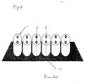
- the cell which is conventionally disposed so as to be perpendicular to the arrangement reference surface, is inclined. That is, in the present invention, the imaginary sectional surface C is inclined with respect to a line perpendicular to the arrangement reference surface D (Fig. 1).
- Such an arrangement method for the present invention is called as "inclined arrangement”.
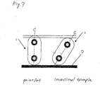
- the inclined angle may be set to a required angle suitably in accordance with the shape of the cell and the shape of the arrangement portion where the cell is disposed. That is, when the cells are disposed lengthwise, the thickness of the arrangement portion can be made small to a required degree, whilst when the cells are disposed widthwise, the height of the arrangement portion can be made small to a required degree (Fig. 7).
- the inclined angle may be obtained through the calculation based on the design drawing of the cell or may be determined while adjusting the inclined angle so that the cell can be housed actually within the arrangement portion.
- the cells can be disposed without changing the design of the each cell within such a limited space where the cell can not be disposed perpendicularly with respect to the arrangement reference surface.
- the cells of the elliptic cylindrical shape to be disposed are preferably disposed in a manner that the lid walls or the bottom walls thereof are aligned on the same plane. This is because the volume efficiency of the cells thus arranged is good and the terminals of the cells can be coupled easily from one another.
- the cells are arranged so as to have a space therebetween as shown Fig. 1 because the cooling efficiency of the cells is improved.
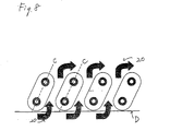
- Fig. 8 when the cells are arranged in a manner that the angle between the imaginary sectional surface C of the direction where the cells are disposed and the arrangement reference surface D of the direction from which the coolant flows in forms an obtuse angle, the resistance to the coolant when flowing the coolant among the cells can be made small and so the coolant flows smoothly.
- the cells are mounted on an electric car or the like, since in most cases the car is provided with an air intake opening on the travelling side and an air exhaust opening on the opposite side, the coolant flows into the cells from the air inlet opening side.
- the cell may be configured in a manner that the sectional shape thereof is elliptic as shown in Fig. 9.
- the external casing thereof is not limited in material and shape to particular ones, and the material and shape thereof may be selected suitably. That is, the material may be formed by using metal, resin etc.
- the material with a low electric conductivity or the flame retardant material is preferable, and further it is more preferable when the material has insulative property.
- the insulative and flame retardant composite resin such as ABS resin is preferable.
- the configuration of the external casing may be formed in accordance with the space where the assembled battery is disposed.
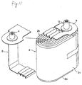
- the power generation element 2 of the non-aqueous electrolyte secondary cell 1 is formed in a manner that a belt-shaped positive electrode 2a and a belt-shaped negative electrode 2b are wound in an elliptic cylindrical shape through a belt-shaped separator 2c as shown in Fig. 10.
- a negative collector 9 is coupled and fixed to the upper end portion of the negative electrode 2b extending upward of the power generation element 2, and a positive collector 8 is coupled and fixed to the lower end portion of the positive electrode 2a extending downward of the power generation element 2.
- the positive collector 8 is extended at its one end to the upper portion of the negative collector 9, and a positive electrode terminal 4 made of aluminum alloy is fixedly coupled to the extended upper portion by means of a caulking process, a welding process etc.
- the power generation element 2 formed by coupling the positive collector 8 and the negative collector 9 is housed within the main body of the cell main body casing 3 of an elliptic cylindrical shape as shown in Fig. 2.
- the main body of the cell main body casing 3 is formed by an aluminum alloy plate, a stainless steel plate or the like.
- the cell casing is formed in a manner that a lid wall 6 of an elliptic shape is fitted in an opening portion at the upper end of the main body of the elliptic cylindrical casing and the periphery of the lid wall is fixedly sealed by a welding process or the like.
- the positive electrode terminal 4 and a negative electrode terminal 5 fixedly coupled to the power generation element 2 are protruded upward through two opening holes provided at the lid wall 6 from the inner side thereof, and these terminals are insulatively and fixedly sealed by a glass hermetic seal formed in a space between the both opening holes.
- the elliptic cylindrical cell is specified in a manner that a nominal voltage is 3.6 volt, a rated capacity is 110 Ah, the height of the external size is 210 mm, a width is 130 mm, a thickness is 50 mm, a mass is 2,780 g, and an energy density is 316 Wh/l, 129 Wh/kg.
- Each of the lid wall and the bottom wall is configured in an elliptic shape having a major axis of 130 mm, a minor axis of 50 mm and semi-circular portions with a radius of 25 mm at both ends.
- the cell casing has an arc-shaped side wall 3a.
- Each of the elliptic cylindrical cells thus formed is disposed in a manner that the arc-shaped side wall of the cell casing is made in contact with the bottom wall of the cell arrangement portion, and the cells are arranged substantially in parallel from one another.
- the height of the cell is 130 mm.
- the height of the cell can be arbitrary adjusted between 70 mm and 130 mm (see Fig. 7).
- the imaginary sectional surface C is inclined by 20 degrees from the vertical line.
- the thickness of the cell arrangement portion can be made small and the cells can be mounted in a small space beneath the floor of the vehicle body.
- the elliptic cylindrical cells are disposed in an inclined manner, the height of the cells at the time of the arrangement can be made small without changing the design of the cells.
- the cells of the present invention can be mounted on various kinds of cell arrangement portions of an electric car etc. manufactured in accordance with the standards unique to the respective manufacturing companies, and so the cost of the cells can be reduced and the efficiency of mounting procedure of the cells can be improved.
- the terminals of the cells can be coupled easily from one another and the volume efficiency of the cells can be improved.
- the cells of the elliptic cylindrical shape are disposed so as to have a space therebetween, the cooling efficiency of the cells can be improved.
Landscapes
- Chemical & Material Sciences (AREA)
- Chemical Kinetics & Catalysis (AREA)
- Electrochemistry (AREA)
- General Chemical & Material Sciences (AREA)
- Engineering & Computer Science (AREA)
- Manufacturing & Machinery (AREA)
- General Physics & Mathematics (AREA)
- Algebra (AREA)
- Physics & Mathematics (AREA)
- Mathematical Analysis (AREA)
- Mathematical Optimization (AREA)
- Pure & Applied Mathematics (AREA)
- Battery Mounting, Suspending (AREA)
- Secondary Cells (AREA)
- Electric Propulsion And Braking For Vehicles (AREA)
- Sealing Battery Cases Or Jackets (AREA)
Applications Claiming Priority (2)
| Application Number | Priority Date | Filing Date | Title |
|---|---|---|---|
| JP20746999 | 1999-07-22 | ||
| JP20746999A JP4355868B2 (ja) | 1999-07-22 | 1999-07-22 | 長円筒形電池の組電池および配置方法 |
Publications (1)
| Publication Number | Publication Date |
|---|---|
| EP1071152A1 true EP1071152A1 (en) | 2001-01-24 |
Family
ID=16540289
Family Applications (1)
| Application Number | Title | Priority Date | Filing Date |
|---|---|---|---|
| EP20000115754 Withdrawn EP1071152A1 (en) | 1999-07-22 | 2000-07-21 | Method for arranging elliptic cylindrical cell and assembled battery |
Country Status (5)
| Country | Link |
|---|---|
| US (1) | US6495282B1 (https=) |
| EP (1) | EP1071152A1 (https=) |
| JP (1) | JP4355868B2 (https=) |
| KR (1) | KR20010039734A (https=) |
| CN (1) | CN1208865C (https=) |
Cited By (1)
| Publication number | Priority date | Publication date | Assignee | Title |
|---|---|---|---|---|
| US7466102B2 (en) | 2004-11-16 | 2008-12-16 | Saab Automobile Ab | Battery unit and vehicle equipped with such a battery unit |
Families Citing this family (21)
| Publication number | Priority date | Publication date | Assignee | Title |
|---|---|---|---|---|
| JP2003031187A (ja) * | 2001-07-17 | 2003-01-31 | Matsushita Electric Ind Co Ltd | 二次電池および電池パック |
| TWI280677B (en) * | 2003-02-18 | 2007-05-01 | Sony Chemicals & Information D | Liquid absorbing sheet and nonaqueous electrolyte battery pack |
| JP5040056B2 (ja) * | 2004-02-17 | 2012-10-03 | パナソニック株式会社 | 略長円形状電池 |
| JP4765439B2 (ja) * | 2004-07-23 | 2011-09-07 | ソニー株式会社 | 電池パック |
| KR100728192B1 (ko) | 2005-10-10 | 2007-06-13 | 삼성에스디아이 주식회사 | 이차 전지 모듈 |
| US7662508B2 (en) | 2004-11-30 | 2010-02-16 | Samsung Sdi Co., Ltd. | Secondary battery module |
| KR100637468B1 (ko) * | 2004-11-30 | 2006-10-23 | 삼성에스디아이 주식회사 | 이차 전지 모듈 |
| JP2006185756A (ja) * | 2004-12-28 | 2006-07-13 | Matsushita Electric Ind Co Ltd | 電池パック |
| KR20060102853A (ko) | 2005-03-25 | 2006-09-28 | 삼성에스디아이 주식회사 | 이차 전지 모듈 |
| EP1864351B1 (en) * | 2005-03-30 | 2012-09-12 | Johnson Controls Technology Company | Battery system assembly |
| JP2008097959A (ja) * | 2006-10-11 | 2008-04-24 | Hitachi Vehicle Energy Ltd | 組電池、サブモジュールおよびモジュール |
| USD586767S1 (en) * | 2007-02-26 | 2009-02-17 | Kemet Electronics Corporation | Anodes |
| JP2009225875A (ja) * | 2008-03-19 | 2009-10-08 | Olympus Corp | 内視鏡システム |
| JP2012028228A (ja) * | 2010-07-26 | 2012-02-09 | Denso Corp | 電池冷却装置 |
| US20120028094A1 (en) * | 2010-07-27 | 2012-02-02 | Yongsam Kim | Battery pack |
| JP2012113874A (ja) * | 2010-11-22 | 2012-06-14 | Toshiba Corp | 組電池装置 |
| JP5547101B2 (ja) * | 2011-01-14 | 2014-07-09 | 日立ビークルエナジー株式会社 | 電池モジュール |
| US9478779B2 (en) * | 2014-08-20 | 2016-10-25 | Ford Global Technologies, Llc | Cell to cell terminal connections for a high voltage battery |
| USD972558S1 (en) * | 2020-12-14 | 2022-12-13 | Meta Platforms Technologies, Llc | Display device |
| WO2023141797A1 (zh) * | 2022-01-26 | 2023-08-03 | 宁德时代新能源科技股份有限公司 | 电池单体和电池 |
| CN116231193B (zh) * | 2023-04-24 | 2026-02-13 | 江苏耀宁新能源创新科技有限公司 | 一种菱形电芯系统 |
Citations (6)
| Publication number | Priority date | Publication date | Assignee | Title |
|---|---|---|---|---|
| US3742832A (en) * | 1972-02-16 | 1973-07-03 | Eastman Kodak Co | Apparatus for receiving a battery holder |
| US4374908A (en) * | 1979-01-30 | 1983-02-22 | Lindholm Alfons S M | Tubular electrode |
| EP0281710A1 (en) * | 1987-03-12 | 1988-09-14 | Yuasa Battery Co., Ltd. | Sealed-battery arrangement |
| JPH04133273A (ja) * | 1990-09-25 | 1992-05-07 | Shin Kobe Electric Mach Co Ltd | 密閉形鉛蓄電池 |
| JPH05238273A (ja) * | 1992-03-02 | 1993-09-17 | Toyota Motor Corp | 電気自動車の電池保持装置 |
| EP0869564A1 (en) * | 1997-03-27 | 1998-10-07 | Japan Storage Battery Company Limited | Nonaqueous electrolyte secondary battery |
Family Cites Families (5)
| Publication number | Priority date | Publication date | Assignee | Title |
|---|---|---|---|---|
| DE4116253C1 (https=) * | 1991-05-17 | 1992-06-04 | Deutsche Automobilgesellschaft Mbh, 3300 Braunschweig, De | |
| US2252088A (en) * | 1939-01-28 | 1941-08-12 | E A Lab Inc | Lamp |
| US4535036A (en) * | 1984-06-04 | 1985-08-13 | Duracell Inc. | Multi-cell power supply |
| JP4116703B2 (ja) * | 1998-07-31 | 2008-07-09 | 古河電池株式会社 | 蓄電池用架台 |
| US6280874B1 (en) * | 1998-12-11 | 2001-08-28 | Schlumberger Technology Corp. | Annular pack |
-
1999
- 1999-07-22 JP JP20746999A patent/JP4355868B2/ja not_active Expired - Fee Related
-
2000
- 2000-07-21 EP EP20000115754 patent/EP1071152A1/en not_active Withdrawn
- 2000-07-21 CN CNB001213512A patent/CN1208865C/zh not_active Expired - Fee Related
- 2000-07-21 KR KR1020000041800A patent/KR20010039734A/ko not_active Ceased
- 2000-07-21 US US09/621,738 patent/US6495282B1/en not_active Expired - Fee Related
Patent Citations (6)
| Publication number | Priority date | Publication date | Assignee | Title |
|---|---|---|---|---|
| US3742832A (en) * | 1972-02-16 | 1973-07-03 | Eastman Kodak Co | Apparatus for receiving a battery holder |
| US4374908A (en) * | 1979-01-30 | 1983-02-22 | Lindholm Alfons S M | Tubular electrode |
| EP0281710A1 (en) * | 1987-03-12 | 1988-09-14 | Yuasa Battery Co., Ltd. | Sealed-battery arrangement |
| JPH04133273A (ja) * | 1990-09-25 | 1992-05-07 | Shin Kobe Electric Mach Co Ltd | 密閉形鉛蓄電池 |
| JPH05238273A (ja) * | 1992-03-02 | 1993-09-17 | Toyota Motor Corp | 電気自動車の電池保持装置 |
| EP0869564A1 (en) * | 1997-03-27 | 1998-10-07 | Japan Storage Battery Company Limited | Nonaqueous electrolyte secondary battery |
Non-Patent Citations (2)
| Title |
|---|
| PATENT ABSTRACTS OF JAPAN vol. 016, no. 401 (E - 1253) 25 August 1992 (1992-08-25) * |
| PATENT ABSTRACTS OF JAPAN vol. 017, no. 697 (M - 1532) 20 December 1993 (1993-12-20) * |
Cited By (1)
| Publication number | Priority date | Publication date | Assignee | Title |
|---|---|---|---|---|
| US7466102B2 (en) | 2004-11-16 | 2008-12-16 | Saab Automobile Ab | Battery unit and vehicle equipped with such a battery unit |
Also Published As
| Publication number | Publication date |
|---|---|
| JP2001035461A (ja) | 2001-02-09 |
| JP4355868B2 (ja) | 2009-11-04 |
| CN1208865C (zh) | 2005-06-29 |
| KR20010039734A (ko) | 2001-05-15 |
| CN1282116A (zh) | 2001-01-31 |
| US6495282B1 (en) | 2002-12-17 |
Similar Documents
| Publication | Publication Date | Title |
|---|---|---|
| US6495282B1 (en) | Method for arranging elliptic cylindrical cell and assembled battery | |
| CN110165114B (zh) | 动力电池包及电动车 | |
| KR100599752B1 (ko) | 이차 전지와 이에 사용되는 전극 조립체 | |
| JP5058986B2 (ja) | 折り曲げ可能なバッテリーカートリッジ及び中または大型バッテリーモジュール | |
| US7790311B2 (en) | Rechargeable battery having lead terminal extending along at least half of a circumference of an electrode assembly | |
| EP2333866B1 (en) | Secondary battery | |
| EP2317588B1 (en) | Secondary battery | |
| US7745046B2 (en) | Secondary battery | |
| US20050221178A1 (en) | Electrode package and secondary battery using the same | |
| JP5356033B2 (ja) | 中型あるいは大型サイズのバッテリパック用カートリッジ | |
| CN116097517B (zh) | 电池、用电设备和电池的制备方法 | |
| KR100612236B1 (ko) | 이차 전지와 이에 사용되는 전극 조립체 | |
| JP2006093154A (ja) | 二次電池 | |
| CN217158363U (zh) | 电池单体、电池以及用电装置 | |
| CN221552047U (zh) | 电池单体、电池和用电装置 | |
| US7794872B2 (en) | Secondary battery | |
| CN221353109U (zh) | 电池及电池包 | |
| KR100599733B1 (ko) | 전극 조립체 및 이의 이차 전지 | |
| US20260031446A1 (en) | Battery cell, battery, and electric apparatus | |
| US12412966B2 (en) | Power storage device | |
| US20250391968A1 (en) | Battery cell, battery and electrical apparatus | |
| KR100612396B1 (ko) | 이차 전지 | |
| KR100578815B1 (ko) | 이차 전지와 이에 사용되는 캡 조립체 | |
| KR100637519B1 (ko) | 이차 전지 | |
| KR20250163062A (ko) | 탭 영역을 포함하는 전극 조립체, 탭 영역을 포함하는 전극 조립체를 포함하는 배터리 셀, 및 이를 포함하는 배터리 장치 |
Legal Events
| Date | Code | Title | Description |
|---|---|---|---|
| PUAI | Public reference made under article 153(3) epc to a published international application that has entered the european phase |
Free format text: ORIGINAL CODE: 0009012 |
|
| AK | Designated contracting states |
Kind code of ref document: A1 Designated state(s): DE FR GB |
|
| AX | Request for extension of the european patent |
Free format text: AL;LT;LV;MK;RO;SI |
|
| 17P | Request for examination filed |
Effective date: 20010618 |
|
| AKX | Designation fees paid |
Free format text: DE FR GB |
|
| RAP1 | Party data changed (applicant data changed or rights of an application transferred) |
Owner name: GS YUASA CORPORATION |
|
| STAA | Information on the status of an ep patent application or granted ep patent |
Free format text: STATUS: THE APPLICATION HAS BEEN WITHDRAWN |
|
| 18W | Application withdrawn |
Effective date: 20070516 |