EP1864351B1 - Battery system assembly - Google Patents
Battery system assembly Download PDFInfo
- Publication number
- EP1864351B1 EP1864351B1 EP05852510A EP05852510A EP1864351B1 EP 1864351 B1 EP1864351 B1 EP 1864351B1 EP 05852510 A EP05852510 A EP 05852510A EP 05852510 A EP05852510 A EP 05852510A EP 1864351 B1 EP1864351 B1 EP 1864351B1
- Authority
- EP
- European Patent Office
- Prior art keywords
- battery module
- battery
- base
- module
- battery system
- Prior art date
- Legal status (The legal status is an assumption and is not a legal conclusion. Google has not performed a legal analysis and makes no representation as to the accuracy of the status listed.)
- Not-in-force
Links
Images


Classifications
-
- H—ELECTRICITY
- H01—ELECTRIC ELEMENTS
- H01M—PROCESSES OR MEANS, e.g. BATTERIES, FOR THE DIRECT CONVERSION OF CHEMICAL ENERGY INTO ELECTRICAL ENERGY
- H01M10/00—Secondary cells; Manufacture thereof
- H01M10/02—Details
-
- B—PERFORMING OPERATIONS; TRANSPORTING
- B60—VEHICLES IN GENERAL
- B60K—ARRANGEMENT OR MOUNTING OF PROPULSION UNITS OR OF TRANSMISSIONS IN VEHICLES; ARRANGEMENT OR MOUNTING OF PLURAL DIVERSE PRIME-MOVERS IN VEHICLES; AUXILIARY DRIVES FOR VEHICLES; INSTRUMENTATION OR DASHBOARDS FOR VEHICLES; ARRANGEMENTS IN CONNECTION WITH COOLING, AIR INTAKE, GAS EXHAUST OR FUEL SUPPLY OF PROPULSION UNITS IN VEHICLES
- B60K1/00—Arrangement or mounting of electrical propulsion units
- B60K1/04—Arrangement or mounting of electrical propulsion units of the electric storage means for propulsion
-
- H—ELECTRICITY
- H01—ELECTRIC ELEMENTS
- H01M—PROCESSES OR MEANS, e.g. BATTERIES, FOR THE DIRECT CONVERSION OF CHEMICAL ENERGY INTO ELECTRICAL ENERGY
- H01M10/00—Secondary cells; Manufacture thereof
- H01M10/04—Construction or manufacture in general
- H01M10/0413—Large-sized flat cells or batteries for motive or stationary systems with plate-like electrodes
-
- H—ELECTRICITY
- H01—ELECTRIC ELEMENTS
- H01M—PROCESSES OR MEANS, e.g. BATTERIES, FOR THE DIRECT CONVERSION OF CHEMICAL ENERGY INTO ELECTRICAL ENERGY
- H01M10/00—Secondary cells; Manufacture thereof
- H01M10/42—Methods or arrangements for servicing or maintenance of secondary cells or secondary half-cells
- H01M10/4207—Methods or arrangements for servicing or maintenance of secondary cells or secondary half-cells for several batteries or cells simultaneously or sequentially
-
- H—ELECTRICITY
- H01—ELECTRIC ELEMENTS
- H01M—PROCESSES OR MEANS, e.g. BATTERIES, FOR THE DIRECT CONVERSION OF CHEMICAL ENERGY INTO ELECTRICAL ENERGY
- H01M50/00—Constructional details or processes of manufacture of the non-active parts of electrochemical cells other than fuel cells, e.g. hybrid cells
- H01M50/20—Mountings; Secondary casings or frames; Racks, modules or packs; Suspension devices; Shock absorbers; Transport or carrying devices; Holders
- H01M50/296—Mountings; Secondary casings or frames; Racks, modules or packs; Suspension devices; Shock absorbers; Transport or carrying devices; Holders characterised by terminals of battery packs
-
- B—PERFORMING OPERATIONS; TRANSPORTING
- B60—VEHICLES IN GENERAL
- B60K—ARRANGEMENT OR MOUNTING OF PROPULSION UNITS OR OF TRANSMISSIONS IN VEHICLES; ARRANGEMENT OR MOUNTING OF PLURAL DIVERSE PRIME-MOVERS IN VEHICLES; AUXILIARY DRIVES FOR VEHICLES; INSTRUMENTATION OR DASHBOARDS FOR VEHICLES; ARRANGEMENTS IN CONNECTION WITH COOLING, AIR INTAKE, GAS EXHAUST OR FUEL SUPPLY OF PROPULSION UNITS IN VEHICLES
- B60K1/00—Arrangement or mounting of electrical propulsion units
- B60K1/04—Arrangement or mounting of electrical propulsion units of the electric storage means for propulsion
- B60K2001/0455—Removal or replacement of the energy storages
-
- Y—GENERAL TAGGING OF NEW TECHNOLOGICAL DEVELOPMENTS; GENERAL TAGGING OF CROSS-SECTIONAL TECHNOLOGIES SPANNING OVER SEVERAL SECTIONS OF THE IPC; TECHNICAL SUBJECTS COVERED BY FORMER USPC CROSS-REFERENCE ART COLLECTIONS [XRACs] AND DIGESTS
- Y02—TECHNOLOGIES OR APPLICATIONS FOR MITIGATION OR ADAPTATION AGAINST CLIMATE CHANGE
- Y02E—REDUCTION OF GREENHOUSE GAS [GHG] EMISSIONS, RELATED TO ENERGY GENERATION, TRANSMISSION OR DISTRIBUTION
- Y02E60/00—Enabling technologies; Technologies with a potential or indirect contribution to GHG emissions mitigation
- Y02E60/10—Energy storage using batteries
-
- Y—GENERAL TAGGING OF NEW TECHNOLOGICAL DEVELOPMENTS; GENERAL TAGGING OF CROSS-SECTIONAL TECHNOLOGIES SPANNING OVER SEVERAL SECTIONS OF THE IPC; TECHNICAL SUBJECTS COVERED BY FORMER USPC CROSS-REFERENCE ART COLLECTIONS [XRACs] AND DIGESTS
- Y02—TECHNOLOGIES OR APPLICATIONS FOR MITIGATION OR ADAPTATION AGAINST CLIMATE CHANGE
- Y02P—CLIMATE CHANGE MITIGATION TECHNOLOGIES IN THE PRODUCTION OR PROCESSING OF GOODS
- Y02P70/00—Climate change mitigation technologies in the production process for final industrial or consumer products
- Y02P70/50—Manufacturing or production processes characterised by the final manufactured product
Definitions
- the present inventions relate to batteries and battery systems. More specifically, the present inventions relate to batteries (e.g., lithium-ion batteries, lithium-polymer batteries, etc.) and systems using such batteries.
- batteries e.g., lithium-ion batteries, lithium-polymer batteries, etc.
- batteries for use in vehicles such as automobiles
- lead-acid batteries have been used in starting, lighting, and ignition applications.
- hybrid vehicles have been produced which utilize a battery (e-g., a nickel-metal-hydride battery) in combination with other systems (e.g., an internal combustion engine) to provide power for the vehicle.
- a battery e-g., a nickel-metal-hydride battery
- other systems e.g., an internal combustion engine
- lithium batteries perform differently than nickel-metal-hydride batteries. In some applications, it may be desirable to obtain the enhanced power/performance of a lithium battery. For example, lithium batteries may provide greater specific power than nickel-metal-hydride batteries. However, the application of lithium battery technology may present design and engineering challenges beyond those typically presented in the application of conventional nickel-metal-hydride battery technology.
- the design and management of a lithium battery system that can be advantageously utilized in a hybrid vehicle may involve considerations such as electrical performance monitoring and thermal management.
- a battery systems includes a battery module that includes a plurality of cells electrically connected in series.
- the battery module includes a conductive element for electrically connecting the battery module to other elements in the battery system.
- the battery system also includes a base configured for securing the battery module in place and includes at least one element for electrically connecting the base to the conductive element of the battery module.
- the base includes a rotatable arm for securing the battery module in place relative to the base.
- the conductive element is configured to contact the at least one element for electrically connecting the base to the battery module when the rotatable arm is positioned to secure the battery module in place relative to the base.
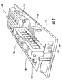
- FIGURE 1 is a perspective view of a battery system according to an exemplary embodiment showing a battery module ready for insertion into the battery system.
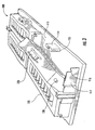
- FIGURE 2 is a perspective view showing the battery system shown in FIGURE 1 with the battery module lowered into place within the battery system.
- FIGURE 3 is a perspective view of the battery system shown in FIGURE 1 showing the rotation of the battery module within the battery system.
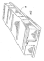
- FIGURE 4 is a perspective view of the battery system shown in FIGURE 1 showing the battery module in place within the battery system and a cover being lowered over the battery modules.
- FIGURE 5 is perspective view showing the cover shown in FIGURE 4 provided on the battery system.
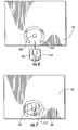
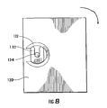
- FIGURES 6-8 are plan view of a portion of the battery system shown in FIGURE 1 illustrating the electrical connection of the battery module.
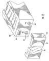
- FIGURE 9 illustrates a portion of a battery system including a battery module similar to that shown in FIGURE 1 that includes a connector according to another exemplary embodiment.
- FIGURE 10 is a partial cutaway plan view of the battery system shown in FIGURE 9 illustrating the positioning of the battery module according to an exemplary embodiment.
- FIGURE 11 is a perspective view of the battery system shown in FIGURE 9 with the battery module provided in its final position.
- FIGURE 12 is a perspective view of a portion of a battery system showing a battery module being put in place according to another exemplary embodiment.
- FIGURE 13 is another perspective view of the portion of the battery system shown in FIGURE 12 .
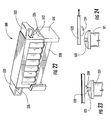
- FIGURE 14 is a perspective view of a battery module having connectors configured for attachment to mounting structures according to another exemplary embodiment.
- FIGURES 15-16 are enlarged views showing the mounting structures illustrated in FIGURE 14 .
- FIGURE 17 is a cross-sectional view of a mounting structure similar to that shown in FIGURES 15-16 according to another exemplary embodiment.
- FIGURES 18-21 illustrate a battery module having features for locking the battery module in place according to another exemplary embodiment.
- FIGURES 22-24 illustrate a battery module having features for retaining the battery module in place according to another exemplary embodiment.
- FIGURE 25 is a perspective view of a battery module having a handle being positioned in a battery base according to an exemplary embodiment.
- FIGURES 26-28 illustrate a battery module having features for retaining the battery module in place according to another exemplary embodiment.
- FIGURE 29 is a perspective view of a connector that may be used to secure a battery module in place according to another exemplary embodiment.
- FIGURE 30 is a perspective view of a connector that may be used to secure at battery module in place according to another exemplary embodiment.
- FIGURES 31-32 illustrate a battery module having features for retaining the battery module in place according to another exemplary embodiment.
- FIGURES 33-36 illustrate a battery module having various latching mechanisms for retaining the battery module in place according to other exemplary embodiments.
- a battery system including a plurality of batteries or cells (e.g., a lithium-ion cell, a lithium-polymer cell, etc.) is provided.
- batteries or cells e.g., a lithium-ion cell, a lithium-polymer cell, etc.
- the features described may be utilized with batteries or cells of any presently known configuration or other configuration (or chemistry) that may be developed in the future.
- One or more batteries may be provided in an assembly or module comprising a plurality of such batteries according to an exemplary embodiment.
- the module may be included in a system that include a plurality of battery modules of any presently known configuration or any other configuration (or chemistry) that may be developed in the future.
- lithium batteries e.g., oval-shaped lithium batteries
- lithium battery systems are shown and described in U.S. Patent Application No.1 10/976,169 . filed October 28, 2004, Publication nr. US2005174092 (It is intended that the batteries, modules, components and other features of the present system may be used in conjunction with features disclosed in U.S. Patent Application No. 10/976,169 ).
- members or elements in the form of connectors are provided on a battery module to allow the battery module to be inserted and retained within a battery system (e.g., attached to a battery tray or other structure to be provided within vehicle such as an automobile).
- a battery system e.g., attached to a battery tray or other structure to be provided within vehicle such as an automobile.
- a member or element such as a base is provided within a vehicle for retaining one or more battery modules (e.g. for a lithium-ion battery system).
- the member or element e.g., a base
- the member or element may be assembled separately from the vehicle and inserted therein subsequent to providing the battery modules within the member or element.
- the member or element e.g., a base
- the member or element may act as a "docking station" into which one or more battery modules (or individual battery cells) may be provided (e.g., to make an electrical connection with the battery module without the need for a separate electrical connection operation during battery system assembly). In this manner, a battery system may be provided which allows for a relatively quick and efficient assembly of the battery system.
- FIGURES 1 through 8 illustrate a battery system 100 including a structure or component 110 in the form of a base or tray (referred to herein for simplicity as a base, although other structures may also be used according to other exemplary embodiments; it should also be noted that elements referred to herein as a "base” or “tray” may be a portion of a base or tray, such as the base 211 shown in FIGURE 12 ) and a plurality of battery modules 120 according to an exemplary embodiment. While FIGURE 1 illustrates a battery system having four modules, it should be understood that according to other exemplary embodiments, any number of battery modules may be included in a battery system depending on a variety of factors, including the amount of power to be delivered, space constraints, and others. For ease of reference, features of the modules 120 will be described with respect to a single module, although it should be understood that such features may be provided for all of the modules used with the battery system 100 or a subset thereof.
- the module 120 includes a plurality of individual cells or batteries 121 (e.g., lithium-ion cells). According to an exemplary embodiment, the module 120 includes twelve cells 121. According to other exemplary embodiments, a different number of cells may be provided in the module.
- batteries 121 e.g., lithium-ion cells.
- the module 120 includes a member or element 122 in the form of a mounting structure for coupling or attaching the module 120 to the base 110.
- the mounting structure 122 at least partially circumscribes a terminal 124 for the module 120.
- the terminal 124 is configured to allow electrical contact to be made between the module 120 and other modules in the battery system 100 (and, consequently, to a vehicle electrical system).
- the base 110 includes a member or element 112 in the form of a mounting structure that is configured to receive the mounting structure 122 and terminal 124 provided on the module 120 (e.g., the terminal 124 is received in the slot defined by the mounting structure 112).
- a member or element 112 in the form of a mounting structure that is configured to receive the mounting structure 122 and terminal 124 provided on the module 120 (e.g., the terminal 124 is received in the slot defined by the mounting structure 112).
- two such mounting structures 112 are provided, such that one is provided at each of the opposite ends of the module 120 when the module 120 is put in place during assembly.
- the mounting structure 112 of the base 110 may be made of a conductive material such as a metal. In this manner, when the module 120 is coupled or attached to the base 110, the terminal 124 will contact the mounting structure 122 provided in the base 110 (shown in the form of a mounting member or structure in FIGURES 1 and 6 , for example) to electrically couple the module 120 to other modules in the battery system 100.
- the module 120 is coupled to the base 110 by providing the terminal 124 of the module 120 within the mounting structure 112 provided on the base 110. As shown in FIGURE 3 , the module 120 is then rotated about the terminal 124.
- a handle 126 interlocks or mates with a member or element 114 in the form of an extension which extends upward from the base 110.
- the handle 126 may include a feature 127 such as a gripping surface to allow for the relatively easy gripping of the handle 126 by an installer.
- the extension 114 may include one or more features 115 configured to lock the module 120 in place flat against the base 110 as that shown in FIGURE 4 .
- the module also includes a member or element 128 in the form of an extension that is configured to be received within a cutout 116 provided in a feature 117 such as a wall or divider provided on the base 110 to provide a relatively secure fit between the module 120 and the base 110.
- the cutout 116 may be configured to relatively secure the member 128 therein (e.g., in gripping fashion) or may simply provide a location on which the member 128 may rest (e.g., with the securing of the module 120 to be accomplished by interaction of the features 115 with the handle 1 26).
- FIGURES 4 and 5 illustrate a cover or shroud 130 configured for use with the battery system 100.
- the cover acts to shield the individual battery modules 120 when the battery system 100 is provided within a vehicle.
- the cover 130 may be made of a polymeric material or other suitable material according to various exemplary embodiments. While FIGURES 4 and 5 illustrate a single cover that acts to cover all of the battery modules in the battery system 100, according to other exemplary embodiments, individual covers may be provided for each of the modules in the battery system. Additionally, according to other exemplary embodiments, the cover may include other features such as electrical connectors, effluent routing systems, and/or other features.
- FIGURES 6-8 illustrate the coupling of the module 120 to the base 110 in greater detail. As shown in FIGURE 6 , the module 120 is lowered toward the mounting structure 122 provided on the base 110 such that the terminal 124 is in alignment with an opening 113 provided in the mounting structure 112 provided on the base 110.
- the mounting structure 112 of the base is received within the mounting structure 122 of the module 120.
- the mounting structure of the module may be received within the mounting structure of the base.
- the module 120 is rotated about the terminal 124 to lock the mounting structure 122 of the module with the mounting structure 112 of the base 110. In this manner, a relatively secure connection between the module 120 and the base 110 may be provided. Additionally, because the mounting structure 112 of the base 110 is made of a conductive material such as a metal, the electrical connection of the module 120 to other modules in the battery system 100 and to the vehicle electrical system may be maintained in a relatively secure manner.
- FIGURES 9-11 illustrate a portion of a battery system 200 according to another exemplary embodiment.
- a battery module 220 e.g., similar to that shown in FIGURE 1 as module 120
- a battery module 220 includes a plurality of individual cells or batteries 221 (e.g., twelve cells). Any number of battery modules may be provided in the battery system 200 as may be desired, with each of the modules having any number of desired cells. According to an exemplary embodiment, four modules are provided in the battery system 200, each of which includes twelve cells.
- the module 220 is also configured such that when the module 220 is assembled with a base, simultaneous mechanical and electrical connections are made such that the need for a separate electrical connection step in the manufacturing process is eliminated.
- a base 210 to which the module 220 is to be coupled includes one or more members or elements in the form of arms. Such arms are shown as arms 250 and 260 in FIGURES 10-11 .
- the module 220 contacts lower portions 254 and 264 of the arms 250 and 254 such that the arms 250 and 260 rotate about pivot points 252 and 262. Such rotation moves upper portions 256 and 266 of the arms 250 and 260 toward the module 220.
- the top portions 256 and 266 of the arms 250 and 260 act to secure the module 220 in place within the battery system 200 (e.g., the top portions 256 and 266 contact the top of the module 220).
- a member or element 240 in the form of a connector (hereafter referred to as “the connector 240") is provided on at least one of the corners of the module 220.
- a connector is provided on at least two of the corners of the module 220 (e.g., to act as "positive” and “negative” terminals for the module 220).
- the connector 240 is a corner block connector that allows for multiple axis attachment of the module 220 within a battery system (such as battery system 200).
- the connector 240 includes three extensions 242, 244, and 246 that are arranged orthogonally which may engage or contact a feature (not shown) provided in the based to provide an electrical connection between the module 220 and the base 210.
- the connectors may allow the module to be used with a variety of different bases, and in a variety of orientations (e.g., by providing connectors on three axes of the module, the battery module may be used with a wider variety of battery systems then may otherwise be possible).
- FIGURES 12-13 illustrate the assembly of a battery system according to another exemplary embodiment.
- a battery module 223 including a plurality of batteries or cells 225 includes on its outer surface two terminals 241 and 243 (positive and negative terminals, respectively) and a pin connector 245.
- the pin connector 245 may provide a data and/or electrical connection between the battery module and interface between the battery module and a battery module controller (not shown).
- a base 211 includes features 213, 215, and 217 for engaging or mating with the terminals 241, 243 and pin connector 245.
- the module may be placed in position by sliding it toward the base 211 to couple the terminals 241, 243 and pin connector 245 to the features 213, 215, and 217 of the base 211.
- An arm 251 may be rotated about a pivot 253 such that a top portion thereof contacts a surface of the module 223.
- the arm 251 may be spring loaded such that it is biased toward the module 223 (e.g., the arm must first be moved away from the module to put the module in place, after which the arm is "let go” such that it clamps against a surface of the module 223 to keep it in place).
- FIGURES 14-17 illustrate portion of a battery system 300 that includes a module 320 having a plurality of cells or batteries 321 according to another exemplary embodiment.
- Members or elements 322 in the form of extensions are provided on the module 320 that extend from a surface thereof.
- Apertures or holes 324 are provided in the extensions 322 to allow the module 320 to be mounted to mounting structures 312 provided as part of a base 310.
- the mounting structures 312 provided in the base 310 are configured similar to seat mounting structures in vehicles. Such mounting structures comprise a cutout or depression into which a feature provided on the battery module may be seated.
- the extensions 322 provided on the module 320 may be configured to be coupled to extensions 314 provided on the mounting structures 312 of the base 310 (e.g., by inserting fasteners 326 through apertures 324 provided in the extensions 322 of the module and apertures 316 provided in the extensions 314 of the mounting structures 312 of the base 310).
- the module 320 shown in FIGURES 14-16 is also configured such that the mechanical connection securing the module in place in the battery system 300 is performed substantially simultaneously with an electrical connection that electrically connects the module 320 to other modules in the battery system 300 and to the vehicle electrical system.
- the extensions 322 of the module 320 may act as terminals for the module 320 such that the connection between the extensions 322 of the module and the extensions 314 of the mounting structures 312 may act to electrically couple the module 320 to the battery system 300.
- the electrical coupling of the battery module 320 may be accomplished by means of a feature 328 provided on the module 320 that may contact an electrical contact 318 provided within the mounting structure 312 when the module 320 is provided in the base 310.
- an electrically conductive member (shown as feature 328 in FIGURE 17 ) extending from the module 320 and configured to couple the module 320 to the mounting structure 312 may be provided such that when the module 320 is provided in place, the electrically conductive member makes contact with the electrical contact 318 provided as part of the mounting structure 312. In this manner, current may be conducted from the battery module 3 20 to the mounting structure 312, and hence to other modules in the battery system 300 and to the vehicle electrical system.
- FIGURES 18-21 illustrate a battery system 400 according to another exemplary embodiment.
- a battery module 420 is provided that includes a feature 422 such as a handle is utilized to make an electrical connection between the module 420 and other modules in the battery system 400 (and to the vehicle electrical system).
- a feature 422 such as a handle is utilized to make an electrical connection between the module 420 and other modules in the battery system 400 (and to the vehicle electrical system).
- contacts 424 on the handle 422 make contact with contacts 402 provided for the battery system 400.
- FIGURES 22-24 illustrate a battery system 500 including a module 520 according to another exemplary embodiment having handles 522 that include contacts 524 that act to connect the module 520 to other elements of the battery system 500 (e.g., other modules, etc.) when the handles are pushed toward the battery module 522.
- the contacts 524 are provided in contact with terminals 523 of an individual cell or battery 521 included in the module 520 (i.e., a circuit is completed with the cells of the battery and the battery system 500).
- a lower portion 526 of the handle is configured to engage a feature 512 (e.g., a mounting structure) provided on a base 510 to mechanically secure the module in place.
- a feature 512 e.g., a mounting structure
- FIGURES 25-36 illustrate various other configurations according to various exemplary embodiments for connecting battery modules to battery systems and for making electrical contact between the battery modules and the battery systems, the benefits of which will be apparent to those of skill in the art reviewing such figures.
- FIGURE 25 illustrates a battery module 620 that includes a handle 622 and a connector 624 that may engage a feature (not shown) provided in a base 610 to electrically and mechanically couple the module 620 to the base 610.
- FIGURES 26-28 illustrate a battery module 720 having a handle 722 that is rotatable about a pivot point 723. Movement of the handle between a first position and a second position may act to move a cam lock 724. In a first position, the cam lock 724 engages a portion of a base 710 to secure the module to the base, as shown in FIGURE 27 . In a second position, the cam lock 724 may be disengaged from the portion of the base 710 such that the module 720 may be attached or detached from the base 710. Electrical connections may be made by virtue of features such as connectors included on the handle 722 or elsewhere on the module.
- FIGURE 29 illustrates a battery module 820 secured to a base 810 using an overcenter latching device 830.
- the latching device may be provided either on the base or on the module (with the corresponding feature to be engaged being provided on the other of the base and module).
- FIGURE 30 illustrates a battery module 920 having a feature 922 configured for engagement by a latch 930 coupled to a base 910.
- the latch 930 is intended to secure the module 920 in place relative to the base 910.
- FIGURES 31-32 illustrate a battery module 1020 having a plurality of cells or batteries 1021, each of which includes terminals 1023 and 1025.
- a hold-down 1040 is provided with contacts 1043 and 1045 such that when the hold-down 1040 is in position (i.e., to lock the module 1020 in place), contact is made between the terminals 1023 and 1025 and the contacts 1043 and 1045, thus electrically connecting the module 1020 to the battery system.
- FIGURES 33-36 illustrate various exemplary embodiments in which battery modules (e.g., modules 1120, 1121, 1122, and 1123) are secured in place to a base (e.g., bases 1110, 1111, 1112, 1113) using a latch such as an over center latch or a partial turn latch (e.g., latches 1130, 1131, 1132, 1133).
- a latch such as an over center latch or a partial turn latch (e.g., latches 1130, 1131, 1132, 1133).
- latches are intended to mechanically secure the modules in place relative to the base.
- Electrical connection between the modules and bases may be provided by features such as contacts provided on the latches or that may be included elsewhere on the modules and/or bases.
- Such embodiments relate generally to the coincidental method for attachment and electrical connection of batteries (e.g., battery modules) to a motor vehicle, more specifically for lithium-ion and capacitor-type batteries.
- batteries e.g., battery modules
- a base of battery module is already provided in a vehicle (like a docking station), and the rest of the components snap into it (e.g. , with a locking mechanism).
- a termination design may be provider to allow the modules to be put into the vehicle in any of three orthogonal orientations (e.g., as shown in FIGURE 9 , in which three extensions or terminals are provided on the corner of the battery module may be utilized). Plug and play venting may be provided in the same area.
- a hold-down mechanism (e.g., such as that shown in FIGURE 11 ) may be used that is similar to the manner in which computer memory is secured to a motherboard.
- handles or other components may be integrated into the battery module to allow any one to grasp and remove the unit. Finger grooves or grips may be provided to allow easy grasping be installer, and the handles may have dual functionality - acting as both a handle and electrical connector.
- a hold-down mechanism similar to that used for vehicle seats may be used (according to one exemplary embodiment, an electrical connection may be made when the connector is put into a trough; it pivots downward into the trough to lock it in, then it is bolted down (the bolt could act as the connector).
- a hold-down mechanism that connects to the terminals of the battery pack may be provided.
- the battery module may be dropped into the connection hold-down mechanism and rotated into place, which may act to lock it in place due to the engagement of features in a base with features on the battery module (see, e.g. FIGURE 1 ).
- the mounting piece can be oriented in any direction so that you can lock it into place either in the upright position or in the laying flat position.
- On the other side of the module e.g., the top of the module
- it could be a separate locking mechanism.
- the locking mechanism could latch into the integral carrying handle in the battery. This is a plug-and-play design that has minimal complexity. This acts as the main hold-down mechanism, and a latch could be used on the other side.
- a hinged door may be provided for the group of modules (e.g., the modules would be arranged side by side, and one side would connect to a connector).
- the door is on the other end, and includes contacts to complete the circuit with the terminals of each module.
- the door may also include sense leads, etc.
- the case can be oriented in any direction (modules could lay flat, could be up and down, etc.).
- the case could also include pins to guide the modules into place.
- a battery system including one or more battery modules may be configured to allow for relatively simple and efficient assembly.
- substantially simultaneous (e.g., coincident) mechanical and electrical connection maybe made between the battery modules and the holder in which they are placed (e.g., a base).
- the need to perform separate mechanical and electrical connections may b e eliminated, thus reducing both labor costs and the number of components (e.g., fasteners, connectors, etc.) that might otherwise be required.
- Coupled and “connected” as used in the this disclosure and in the claims which follow (both in the sense of an electrical connection and a mechanical connection) are intended to be construed broadly to encompass both direct and indirect coupling and connection, unless otherwise indicated.
- elements shown as integrally formed may be constructed of multiple parts or elements, the position of elements may be reversed or otherwise varied (e.g., the variable temperature resistor may be provided adjacent a negative terminal of a battery), and the nature or number of discrete elements or positions may be altered or varied (e.g., a plurality of resistors may be provided in place of a single resistor). Accordingly, all such modifications are intended to be included within the scope of the present invention as defined in the appended claims. The order or sequence of any process or method steps may be varied or re-sequenced according to alternative embodiments. Other substitutions, modifications, changes and omissions may be made in the design, operating conditions and arrangement of the various exemplary embodiments without departing from the scope of the present inventions.
Description
- The government of the United States has rights in this invention pur-suant to Contract No. DE-FC26-95BE50425 awarded by the U.S. Department of Energy.
- The present application claims the benefit of
U.S. Provisional Patent Application No. 60/666,421 filed March 30, 2005 - The present inventions relate to batteries and battery systems. More specifically, the present inventions relate to batteries (e.g., lithium-ion batteries, lithium-polymer batteries, etc.) and systems using such batteries.
- It is known to provide batteries for use in vehicles such as automobiles, For example, lead-acid batteries have been used in starting, lighting, and ignition applications. More recently, hybrid vehicles have been produced which utilize a battery (e-g., a nickel-metal-hydride battery) in combination with other systems (e.g., an internal combustion engine) to provide power for the vehicle.
- It is generally known that lithium batteries perform differently than nickel-metal-hydride batteries. In some applications, it may be desirable to obtain the enhanced power/performance of a lithium battery. For example, lithium batteries may provide greater specific power than nickel-metal-hydride batteries. However, the application of lithium battery technology may present design and engineering challenges beyond those typically presented in the application of conventional nickel-metal-hydride battery technology.
- For example, the design and management of a lithium battery system that can be advantageously utilized in a hybrid vehicle may involve considerations such as electrical performance monitoring and thermal management.
- It would be desirable to provide a system that may be relatively simply and efficiently assembled. It would also be desirable to provide a system that includes a plurality of modules that may be assembled without the use of tools. It would further be desirable to provide a system in which electrical connections may be made when battery modules are assembled in the battery system. It would be desirable to provide a system and/or method that provides any one or more of these or other advantageous features.
US6403251 discloses a battery pack with multiple secure modules having open-sided pockets for temporarily retaining the modules in the pockets. - A battery systems includes a battery module that includes a plurality of cells electrically connected in series. The battery module includes a conductive element for electrically connecting the battery module to other elements in the battery system. The battery system also includes a base configured for securing the battery module in place and includes at least one element for electrically connecting the base to the conductive element of the battery module. The base includes a rotatable arm for securing the battery module in place relative to the base. The conductive element is configured to contact the at least one element for electrically connecting the base to the battery module when the rotatable arm is positioned to secure the battery module in place relative to the base.
-
FIGURE 1 is a perspective view of a battery system according to an exemplary embodiment showing a battery module ready for insertion into the battery system. -
FIGURE 2 is a perspective view showing the battery system shown inFIGURE 1 with the battery module lowered into place within the battery system. -
FIGURE 3 is a perspective view of the battery system shown inFIGURE 1 showing the rotation of the battery module within the battery system. -
FIGURE 4 is a perspective view of the battery system shown inFIGURE 1 showing the battery module in place within the battery system and a cover being lowered over the battery modules. -
FIGURE 5 is perspective view showing the cover shown inFIGURE 4 provided on the battery system. -
FIGURES 6-8 are plan view of a portion of the battery system shown inFIGURE 1 illustrating the electrical connection of the battery module. -
FIGURE 9 illustrates a portion of a battery system including a battery module similar to that shown inFIGURE 1 that includes a connector according to another exemplary embodiment. -
FIGURE 10 is a partial cutaway plan view of the battery system shown inFIGURE 9 illustrating the positioning of the battery module according to an exemplary embodiment. -
FIGURE 11 is a perspective view of the battery system shown inFIGURE 9 with the battery module provided in its final position. -
FIGURE 12 is a perspective view of a portion of a battery system showing a battery module being put in place according to another exemplary embodiment. -
FIGURE 13 is another perspective view of the portion of the battery system shown inFIGURE 12 . -
FIGURE 14 is a perspective view of a battery module having connectors configured for attachment to mounting structures according to another exemplary embodiment. -
FIGURES 15-16 are enlarged views showing the mounting structures illustrated inFIGURE 14 . -
FIGURE 17 is a cross-sectional view of a mounting structure similar to that shown inFIGURES 15-16 according to another exemplary embodiment. -
FIGURES 18-21 illustrate a battery module having features for locking the battery module in place according to another exemplary embodiment. -
FIGURES 22-24 illustrate a battery module having features for retaining the battery module in place according to another exemplary embodiment. -
FIGURE 25 is a perspective view of a battery module having a handle being positioned in a battery base according to an exemplary embodiment. -
FIGURES 26-28 illustrate a battery module having features for retaining the battery module in place according to another exemplary embodiment. -
FIGURE 29 is a perspective view of a connector that may be used to secure a battery module in place according to another exemplary embodiment. -
FIGURE 30 is a perspective view of a connector that may be used to secure at battery module in place according to another exemplary embodiment. -
FIGURES 31-32 illustrate a battery module having features for retaining the battery module in place according to another exemplary embodiment. -
FIGURES 33-36 illustrate a battery module having various latching mechanisms for retaining the battery module in place according to other exemplary embodiments. - According to an exemplary embodiment, a battery system including a plurality of batteries or cells (e.g., a lithium-ion cell, a lithium-polymer cell, etc.) is provided. It should be noted that while particular exemplary embodiments are shown and described in the present disclosure, the features described may be utilized with batteries or cells of any presently known configuration or other configuration (or chemistry) that may be developed in the future.
- One or more batteries (or cells) may be provided in an assembly or module comprising a plurality of such batteries according to an exemplary embodiment. According to an exemplary embodiment in which a module including a plurality of batteries is provided, the module may be included in a system that include a plurality of battery modules of any presently known configuration or any other configuration (or chemistry) that may be developed in the future.
- Various exemplary embodiments of lithium batteries (e.g., oval-shaped lithium batteries) and lithium battery systems are shown and described in
U.S. Patent Application No.1 10/976,169 . filedOctober 28, 2004, Publication nr. US2005174092 (It is intended that the batteries, modules, components and other features of the present system may be used in conjunction with features disclosed inU.S. Patent Application No. 10/976,169 ). - According to various exemplary embodiments, members or elements in the form of connectors are provided on a battery module to allow the battery module to be inserted and retained within a battery system (e.g., attached to a battery tray or other structure to be provided within vehicle such as an automobile). It should be understood by those of skill in the art reviewing the present disclosure that while particular exemplary embodiments are shown and described herein, the concepts disclosed should not be construed as limited to these particular exemplary embodiments, and that various other exemplary embodiments as may be apparent to those reviewing this disclosure are intended to be included within the scope of the present inventions.
- According to an exemplary embodiment, a member or element such as a base is provided within a vehicle for retaining one or more battery modules (e.g. for a lithium-ion battery system). According to another exemplary embodiment, the member or element (e.g., a base) may be assembled separately from the vehicle and inserted therein subsequent to providing the battery modules within the member or element. According to an exemplary embodiment, the member or element (e.g., a base) may act as a "docking station" into which one or more battery modules (or individual battery cells) may be provided (e.g., to make an electrical connection with the battery module without the need for a separate electrical connection operation during battery system assembly). In this manner, a battery system may be provided which allows for a relatively quick and efficient assembly of the battery system.
-
FIGURES 1 through 8 illustrate abattery system 100 including a structure orcomponent 110 in the form of a base or tray (referred to herein for simplicity as a base, although other structures may also be used according to other exemplary embodiments; it should also be noted that elements referred to herein as a "base" or "tray" may be a portion of a base or tray, such as thebase 211 shown inFIGURE 12 ) and a plurality ofbattery modules 120 according to an exemplary embodiment. WhileFIGURE 1 illustrates a battery system having four modules, it should be understood that according to other exemplary embodiments, any number of battery modules may be included in a battery system depending on a variety of factors, including the amount of power to be delivered, space constraints, and others. For ease of reference, features of themodules 120 will be described with respect to a single module, although it should be understood that such features may be provided for all of the modules used with thebattery system 100 or a subset thereof. - The
module 120 includes a plurality of individual cells or batteries 121 (e.g., lithium-ion cells). According to an exemplary embodiment, themodule 120 includes twelvecells 121. According to other exemplary embodiments, a different number of cells may be provided in the module. - As shown in
FIGURE 1 , themodule 120 includes a member orelement 122 in the form of a mounting structure for coupling or attaching themodule 120 to thebase 110. According to an exemplary embodiment, the mountingstructure 122 at least partially circumscribes a terminal 124 for themodule 120. The terminal 124 is configured to allow electrical contact to be made between themodule 120 and other modules in the battery system 100 (and, consequently, to a vehicle electrical system). - As shown in
FIGURE 1 , thebase 110 includes a member orelement 112 in the form of a mounting structure that is configured to receive the mountingstructure 122 and terminal 124 provided on the module 120 (e.g., the terminal 124 is received in the slot defined by the mounting structure 112). According to an exemplary embodiment, two such mountingstructures 112 are provided, such that one is provided at each of the opposite ends of themodule 120 when themodule 120 is put in place during assembly. - The mounting
structure 112 of the base 110 may be made of a conductive material such as a metal. In this manner, when themodule 120 is coupled or attached to thebase 110, the terminal 124 will contact the mountingstructure 122 provided in the base 110 (shown in the form of a mounting member or structure inFIGURES 1 and6 , for example) to electrically couple themodule 120 to other modules in thebattery system 100. - As shown in
FIGURE 2 , themodule 120 is coupled to thebase 110 by providing theterminal 124 of themodule 120 within the mountingstructure 112 provided on thebase 110. As shown inFIGURE 3 , themodule 120 is then rotated about theterminal 124. Ahandle 126 interlocks or mates with a member orelement 114 in the form of an extension which extends upward from thebase 110. Thehandle 126 may include afeature 127 such as a gripping surface to allow for the relatively easy gripping of thehandle 126 by an installer. Theextension 114 may include one ormore features 115 configured to lock themodule 120 in place flat against the base 110 as that shown inFIGURE 4 . As can be seen fromFIGURES 3 and4 , the module also includes a member orelement 128 in the form of an extension that is configured to be received within acutout 116 provided in afeature 117 such as a wall or divider provided on the base 110 to provide a relatively secure fit between themodule 120 and thebase 110. Thecutout 116 may be configured to relatively secure themember 128 therein (e.g., in gripping fashion) or may simply provide a location on which themember 128 may rest (e.g., with the securing of themodule 120 to be accomplished by interaction of thefeatures 115 with the handle 1 26). -
FIGURES 4 and5 illustrate a cover orshroud 130 configured for use with thebattery system 100. The cover acts to shield theindividual battery modules 120 when thebattery system 100 is provided within a vehicle. Thecover 130 may be made of a polymeric material or other suitable material according to various exemplary embodiments. WhileFIGURES 4 and5 illustrate a single cover that acts to cover all of the battery modules in thebattery system 100, according to other exemplary embodiments, individual covers may be provided for each of the modules in the battery system. Additionally, according to other exemplary embodiments, the cover may include other features such as electrical connectors, effluent routing systems, and/or other features. -
FIGURES 6-8 illustrate the coupling of themodule 120 to the base 110 in greater detail. As shown inFIGURE 6 , themodule 120 is lowered toward the mountingstructure 122 provided on the base 110 such that the terminal 124 is in alignment with anopening 113 provided in the mountingstructure 112 provided on thebase 110. - As shown in
FIGURE 7 , when themodule 120 is lowered such that theterminal 124 of themodule 120 is seated within theopening 113, the mountingstructure 112 of the base is received within the mountingstructure 122 of themodule 120. According to other exemplary embodiments, the mounting structure of the module may be received within the mounting structure of the base. - As shown in
FIGURE 8 , once themodule 120 is provided such that the terminal 124 is seated within the mountingstructure 112 of thebase 110, themodule 120 is rotated about the terminal 124 to lock the mountingstructure 122 of the module with the mountingstructure 112 of thebase 110. In this manner, a relatively secure connection between themodule 120 and the base 110 may be provided. Additionally, because the mountingstructure 112 of thebase 110 is made of a conductive material such as a metal, the electrical connection of themodule 120 to other modules in thebattery system 100 and to the vehicle electrical system may be maintained in a relatively secure manner. -
FIGURES 9-11 illustrate a portion of abattery system 200 according to another exemplary embodiment. As shown inFIGURE 9 , a battery module 220 (e.g., similar to that shown inFIGURE 1 as module 120) includes a plurality of individual cells or batteries 221 (e.g., twelve cells). Any number of battery modules may be provided in thebattery system 200 as may be desired, with each of the modules having any number of desired cells. According to an exemplary embodiment, four modules are provided in thebattery system 200, each of which includes twelve cells. - The
module 220 is also configured such that when themodule 220 is assembled with a base, simultaneous mechanical and electrical connections are made such that the need for a separate electrical connection step in the manufacturing process is eliminated. For example, according to an exemplary embodiment shown inFIGURES 10-11 , a base 210 to which themodule 220 is to be coupled includes one or more members or elements in the form of arms. Such arms are shown asarms FIGURES 10-11 . As themodule 220 is lowered into place within thebattery system 200, themodule 220 contactslower portions arms arms upper portions arms module 220. As shown inFIGURE 11 , when themodule 220 is completely in place within thebattery system 200, thetop portions arms module 220 in place within the battery system 200 (e.g., thetop portions - As shown in
FIGURE 9 , a member orelement 240 in the form of a connector (hereafter referred to as "theconnector 240") is provided on at least one of the corners of themodule 220. According to an exemplary embodiment, such a connector is provided on at least two of the corners of the module 220 (e.g., to act as "positive" and "negative" terminals for the module 220). Theconnector 240 is a corner block connector that allows for multiple axis attachment of themodule 220 within a battery system (such as battery system 200). For example, as shown inFIGURE 9 , theconnector 240 includes threeextensions module 220 and thebase 210. - One advantageous feature of the embodiment shown and described with respect to
FIGURES 9-11 is that the connectors may allow the module to be used with a variety of different bases, and in a variety of orientations (e.g., by providing connectors on three axes of the module, the battery module may be used with a wider variety of battery systems then may otherwise be possible). -
FIGURES 12-13 illustrate the assembly of a battery system according to another exemplary embodiment. Abattery module 223 including a plurality of batteries orcells 225 includes on its outer surface twoterminals 241 and 243 (positive and negative terminals, respectively) and apin connector 245. Thepin connector 245 may provide a data and/or electrical connection between the battery module and interface between the battery module and a battery module controller (not shown). - As shown in
FIGURE 13 , abase 211 includesfeatures terminals pin connector 245. According to this embodiment, the module may be placed in position by sliding it toward the base 211 to couple theterminals pin connector 245 to thefeatures base 211. Anarm 251 may be rotated about apivot 253 such that a top portion thereof contacts a surface of themodule 223. According to an exemplary embodiment, thearm 251 may be spring loaded such that it is biased toward the module 223 (e.g., the arm must first be moved away from the module to put the module in place, after which the arm is "let go" such that it clamps against a surface of themodule 223 to keep it in place). -
FIGURES 14-17 illustrate portion of a battery system 300 that includes a module 320 having a plurality of cells orbatteries 321 according to another exemplary embodiment. Members orelements 322 in the form of extensions are provided on the module 320 that extend from a surface thereof. Apertures or holes 324 are provided in theextensions 322 to allow the module 320 to be mounted to mountingstructures 312 provided as part of a base 310. - As shown in
FIGURES 15-16 , the mountingstructures 312 provided in the base 310 are configured similar to seat mounting structures in vehicles. Such mounting structures comprise a cutout or depression into which a feature provided on the battery module may be seated. According to an exemplary embodiment, theextensions 322 provided on the module 320 may be configured to be coupled toextensions 314 provided on the mountingstructures 312 of the base 310 (e.g., by insertingfasteners 326 throughapertures 324 provided in theextensions 322 of the module andapertures 316 provided in theextensions 314 of the mountingstructures 312 of the base 310). - The module 320 shown in
FIGURES 14-16 is also configured such that the mechanical connection securing the module in place in the battery system 300 is performed substantially simultaneously with an electrical connection that electrically connects the module 320 to other modules in the battery system 300 and to the vehicle electrical system. For example, according to one exemplary embodiment, theextensions 322 of the module 320 may act as terminals for the module 320 such that the connection between theextensions 322 of the module and theextensions 314 of the mountingstructures 312 may act to electrically couple the module 320 to the battery system 300. - According to another exemplary embodiment shown in
FIGURE 17 , the electrical coupling of the battery module 320 may be accomplished by means of afeature 328 provided on the module 320 that may contact anelectrical contact 318 provided within the mountingstructure 312 when the module 320 is provided in the base 310. For example, an electrically conductive member (shown asfeature 328 inFIGURE 17 ) extending from the module 320 and configured to couple the module 320 to the mountingstructure 312 may be provided such that when the module 320 is provided in place, the electrically conductive member makes contact with theelectrical contact 318 provided as part of the mountingstructure 312. In this manner, current may be conducted from thebattery module 3 20 to the mountingstructure 312, and hence to other modules in the battery system 300 and to the vehicle electrical system. -
FIGURES 18-21 illustrate abattery system 400 according to another exemplary embodiment. As shown inFIGURES 18-21 , abattery module 420 is provided that includes afeature 422 such as a handle is utilized to make an electrical connection between themodule 420 and other modules in the battery system 400 (and to the vehicle electrical system). As shown inFIGURE 20 , when thehandle 422 of themodule 420 is moved into a "locked" position in which the handle is coupled to a mounting structure of the base (as shown inFIGURE 18 ),contacts 424 on thehandle 422 make contact withcontacts 402 provided for thebattery system 400. When thehandle 422 is pushed into the "unlocked" position in which the handle is not coupled to the mounting structure (as shown inFIGURE 19 ), thecontacts 424 for thehandle 422 and thecontacts 402 for thebattery system 400 are no longer in alignment (as shown inFIGURE 21 ). -
FIGURES 22-24 illustrate abattery system 500 including amodule 520 according to another exemplaryembodiment having handles 522 that includecontacts 524 that act to connect themodule 520 to other elements of the battery system 500 (e.g., other modules, etc.) when the handles are pushed toward thebattery module 522. As shown inFIGURE 23 , when thehandles 522 are moved to the "locked" or "connected position," thecontacts 524 are provided in contact withterminals 523 of an individual cell orbattery 521 included in the module 520 (i.e., a circuit is completed with the cells of the battery and the battery system 500). Alower portion 526 of the handle is configured to engage a feature 512 (e.g., a mounting structure) provided on a base 510 to mechanically secure the module in place. Thus, when the handles are moved to the "locked" or "connected position," electrical contact is made between themodule 520 and thebattery system 500 substantially simultaneously with the mechanical interconnection (e.g., interlocking) of thehandle 522 and thefeature 512 of the base 510 (and, on the contrary, such contact is broken when the handle is moved to the "unlocked" or "disconnected" position). -
FIGURES 25-36 illustrate various other configurations according to various exemplary embodiments for connecting battery modules to battery systems and for making electrical contact between the battery modules and the battery systems, the benefits of which will be apparent to those of skill in the art reviewing such figures. - For example,
FIGURE 25 illustrates abattery module 620 that includes ahandle 622 and aconnector 624 that may engage a feature (not shown) provided in a base 610 to electrically and mechanically couple themodule 620 to thebase 610. -
FIGURES 26-28 illustrate abattery module 720 having ahandle 722 that is rotatable about apivot point 723. Movement of the handle between a first position and a second position may act to move acam lock 724. In a first position, thecam lock 724 engages a portion of a base 710 to secure the module to the base, as shown inFIGURE 27 . In a second position, thecam lock 724 may be disengaged from the portion of the base 710 such that themodule 720 may be attached or detached from thebase 710. Electrical connections may be made by virtue of features such as connectors included on thehandle 722 or elsewhere on the module. -
FIGURE 29 illustrates abattery module 820 secured to a base 810 using anovercenter latching device 830. It will be appreciated by those reviewing this disclosure that the latching device may be provided either on the base or on the module (with the corresponding feature to be engaged being provided on the other of the base and module). -
FIGURE 30 illustrates abattery module 920 having afeature 922 configured for engagement by alatch 930 coupled to abase 910. Thelatch 930 is intended to secure themodule 920 in place relative to thebase 910. -
FIGURES 31-32 illustrate abattery module 1020 having a plurality of cells orbatteries 1021, each of which includesterminals down 1040 is provided withcontacts down 1040 is in position (i.e., to lock themodule 1020 in place), contact is made between theterminals contacts module 1020 to the battery system. -
FIGURES 33-36 illustrate various exemplary embodiments in which battery modules (e.g.,modules bases - It will be appreciated by those of skill in the art that various exemplary embodiments are disclosed herein. Such embodiments relate generally to the coincidental method for attachment and electrical connection of batteries (e.g., battery modules) to a motor vehicle, more specifically for lithium-ion and capacitor-type batteries. For example, according to an exemplary embodiment such as that shown in
FIGURE 1 , a base of battery module is already provided in a vehicle (like a docking station), and the rest of the components snap into it (e.g. , with a locking mechanism). - According to an exemplary embodiment, a termination design may be provider to allow the modules to be put into the vehicle in any of three orthogonal orientations (e.g., as shown in
FIGURE 9 , in which three extensions or terminals are provided on the corner of the battery module may be utilized). Plug and play venting may be provided in the same area. - According to other exemplary embodiment s, a hold-down mechanism (e.g., such as that shown in
FIGURE 11 ) may be used that is similar to the manner in which computer memory is secured to a motherboard. According to still other exemplary embodiments, handles or other components may be integrated into the battery module to allow any one to grasp and remove the unit. Finger grooves or grips may be provided to allow easy grasping be installer, and the handles may have dual functionality - acting as both a handle and electrical connector. - According to yet still other exemplary embodiments (e.g., as shown in
FIGURES 14-17 ), a hold-down mechanism similar to that used for vehicle seats may be used (according to one exemplary embodiment, an electrical connection may be made when the connector is put into a trough; it pivots downward into the trough to lock it in, then it is bolted down (the bolt could act as the connector). - According to another exemplary embodiment, a hold-down mechanism that connects to the terminals of the battery pack may be provided. According to this embodiment, the battery module may be dropped into the connection hold-down mechanism and rotated into place, which may act to lock it in place due to the engagement of features in a base with features on the battery module (see, e.g.
FIGURE 1 ). The mounting piece can be oriented in any direction so that you can lock it into place either in the upright position or in the laying flat position. On the other side of the module (e.g., the top of the module) could be another type of connector that provides the effluent exhaust system to lock that portion of the module into position. Alternatively, it could be a separate locking mechanism. The locking mechanism could latch into the integral carrying handle in the battery. This is a plug-and-play design that has minimal complexity. This acts as the main hold-down mechanism, and a latch could be used on the other side. - According to another exemplary embodiment, a hinged door may be provided for the group of modules (e.g., the modules would be arranged side by side, and one side would connect to a connector). The door is on the other end, and includes contacts to complete the circuit with the terminals of each module. The door may also include sense leads, etc. The case can be oriented in any direction (modules could lay flat, could be up and down, etc.). The case could also include pins to guide the modules into place.
- The various exemplary embodiments disclosed and described herein may include or exhibit various advantageous features. For example, a battery system including one or more battery modules (each of which includes one or more lithium batteries or cells) may be configured to allow for relatively simple and efficient assembly. In this manner, substantially simultaneous (e.g., coincident) mechanical and electrical connection maybe made between the battery modules and the holder in which they are placed (e.g., a base). Accordingly, the need to perform separate mechanical and electrical connections may b e eliminated, thus reducing both labor costs and the number of components (e.g., fasteners, connectors, etc.) that might otherwise be required.
- The terms "coupled" and "connected" as used in the this disclosure and in the claims which follow (both in the sense of an electrical connection and a mechanical connection) are intended to be construed broadly to encompass both direct and indirect coupling and connection, unless otherwise indicated.
- It is important to note that the construction and arrangement of the system as shown in the various exemplary embodiments is illustrative only. Although only a few embodiments of the present inventions have been described in detail in this disclosure, those skilled in the art who review this disclosure will readily appreciated that many modifications are possible (e.g., variations in sizes, dimensions, structures, shapes and proportions of the various elements, values of parameters, mounting arrangements, use of materials, colors, orientations, etc.) without materially departing from the novel teachings and advantages of the subject matter recited in the claims. For example, elements shown as integrally formed may be constructed of multiple parts or elements, the position of elements may be reversed or otherwise varied (e.g., the variable temperature resistor may be provided adjacent a negative terminal of a battery), and the nature or number of discrete elements or positions may be altered or varied (e.g., a plurality of resistors may be provided in place of a single resistor). Accordingly, all such modifications are intended to be included within the scope of the present invention as defined in the appended claims. The order or sequence of any process or method steps may be varied or re-sequenced according to alternative embodiments. Other substitutions, modifications, changes and omissions may be made in the design, operating conditions and arrangement of the various exemplary embodiments without departing from the scope of the present inventions.
Claims (26)
- A battery system comprising:a battery module (120,1120) comprising a plurality of lithium-ion cells electrically connected in series, the battery module comprising a conductive element (1023,1025) for electrically connecting the battery module to other elements in the battery system;a base (110) configured for securing the battery module in place and comprising at least one element for electrically connecting the base to the conductive element of the battery module;wherein the base comprises a rotatable arm (250, 260) for securing the battery module in place relative to the base;wherein the conductive element is configured to contact the at least one element for electrically connecting the base to the battery module when the rotatable arm is positioned to secure the battery module in place relative to the base.
- The battery system of Claim 1, wherein the plurality of cells in the battery module have a generally oval shape.
- The battery system of Claim 1, wherein the rotatable arm is configured for movement between a first position in which it does not secure the battery module in place and a second position in which it secures the battery module in place.
- The battery system of Claim 3, wherein the rotatable arm is configured for movement between the first position and the second position when the battery module contacts a portion of the rotatable arm.
- The battery system of Claim 3, wherein the rotatable arm is biased toward the second position.
- The battery system of Claim 1, wherein the at least one element for connecting the battery module to the battery system comprises a connector provided at a corner of the battery module.
- The battery system of Claim 6, wherein the connector comprises a plurality of extensions arranged orthogonally at the corner of the battery module.
- The battery system of Claim 7, wherein the battery module comprises two connectors comprising a plurality of extensions arranged orthogonally, a first of the two connectors being provided at a first corner of the battery module and a second of the two connectors being provided at a second corner of the battery module.
- The battery system of Claim 8, wherein the first connector is a positive terminal for the battery module and the second connector is a negative terminal for the battery module.
- The battery system of Claim 1, wherein the battery module comprises a pin connector configured for connection to a portion of the base.
- The battery system of Claim 1, wherein the conductive element comprises a terminal extending from the battery module.
- The battery system of Claim 11, wherein the at least one element for electrically connecting the base to the battery module comprises an aperture configured to receive the terminal therein.
- The battery system of Claim 1, wherein the battery module comprises twelve cells,
- A battery system, comprising:a battery module (120, 1120) comprising a plurality of lithium-ion cells electrically connected together and at least one terminal extending from the battery module;a base configured to provide an electrical connection with the battery module when the battery module is mechanically coupled to the base, at least one of the base and the battery module comprising a mounting structure (112, 122, 312) configured for movement from a first position to a second position, the mounting structure configured to provide both electrical and mechanical coupling between the base and the battery module when the mounting structure is in the second position,
- The battery system of Claim 14, wherein the mounting structure comprises a slot for receiving the at least one terminal.
- The battery system of Claim 15, wherein the battery module comprises the mounting structure configured for movement from a first position to a second position, the mounting structure provided proximate the at least one terminals, wherein the mounting structure of the battery module is configured to mechanically interlock with a mounting structure of the base.
- The battery system of Claim 16, wherein the mounting structure of the base is configured to mechanically interlock with the mounting structure of the battery module when the battery module is rotated relative to the base about the at least one terminal.
- The battery system of Claim 17, wherein the battery module comprises a handle and the base comprises an extension configured to engage at least a portion of the handle when the battery module is secured to the base.
- The battery system of Claim 14, wherein the mounting structure is a latch.
- The battery system of Claim 14, wherein the battery module comprises an extension for coupling to the base and the base comprises a contact for making an electrical contact with the at least one terminal.
- The battery system of Claim 14, wherein the battery module comprises a handle configured for movement relative to the battery module, the handle configured to interlock with the base and comprising at least one contact for electrically connecting the at least one terminal to the base.
- The battery system of Claim 21, wherein the at least one terminal is a terminal of a cell included in the module.
- The battery system of Claim 21, wherein the handle comprises a cam lock configured to engage the mounting structure of the base.
- The battery system of Claim 14, wherein the mounting structure comprises a latch.
- The battery system of Claim 14, wherein the mounting structure comprises a hold-down that comprises a plurality of contacts for contacting a plurality of terminals of the battery module.
- The battery system of Claim 14, wherein the battery module comprises twelve cells.
Applications Claiming Priority (2)
| Application Number | Priority Date | Filing Date | Title |
|---|---|---|---|
| US66642105P | 2005-03-30 | 2005-03-30 | |
| PCT/US2005/043289 WO2006118612A1 (en) | 2005-03-30 | 2005-11-30 | Battery system assembly |
Publications (2)
| Publication Number | Publication Date |
|---|---|
| EP1864351A1 EP1864351A1 (en) | 2007-12-12 |
| EP1864351B1 true EP1864351B1 (en) | 2012-09-12 |
Family
ID=36581866
Family Applications (1)
| Application Number | Title | Priority Date | Filing Date |
|---|---|---|---|
| EP05852510A Not-in-force EP1864351B1 (en) | 2005-03-30 | 2005-11-30 | Battery system assembly |
Country Status (4)
| Country | Link |
|---|---|
| US (1) | US20080268330A1 (en) |
| EP (1) | EP1864351B1 (en) |
| JP (1) | JP2008535176A (en) |
| WO (1) | WO2006118612A1 (en) |
Cited By (4)
| Publication number | Priority date | Publication date | Assignee | Title |
|---|---|---|---|---|
| CN104066607A (en) * | 2012-03-27 | 2014-09-24 | 台湾立凯绿能移动股份有限公司 | Fixing device group for removable battery of electric vehicle, and locking method thereof |
| US9627908B2 (en) | 2012-03-13 | 2017-04-18 | Maxwell Technologies, Inc. | Ultracapacitor and battery combination with electronic management system |
| DE102017210357A1 (en) | 2017-06-21 | 2018-12-27 | Audi Ag | Battery device, battery system and method for mounting a battery system |
| DE102020115347A1 (en) | 2020-06-09 | 2021-12-09 | Audi Aktiengesellschaft | Battery system, motor vehicle with a battery system and method for mounting a battery system in a motor vehicle |
Families Citing this family (23)
| Publication number | Priority date | Publication date | Assignee | Title |
|---|---|---|---|---|
| KR100783895B1 (en) * | 2006-09-28 | 2007-12-10 | 현대자동차주식회사 | Battery mounting structure of a hybrid vehicle |
| US8129046B2 (en) * | 2008-09-02 | 2012-03-06 | Dwyer Instruments, Inc. | Intrinsically safe battery pack and system |
| CN101728494B (en) * | 2008-10-13 | 2013-03-13 | 深圳富泰宏精密工业有限公司 | Locking mechanism of battery cover |
| JP5330810B2 (en) * | 2008-11-18 | 2013-10-30 | 株式会社日立製作所 | Battery box for storing battery module and railcar equipped with the same |
| TWI357865B (en) * | 2008-12-03 | 2012-02-11 | Ind Tech Res Inst | A swift pluggable and lockable battery structure |
| CN101830161A (en) * | 2010-04-17 | 2010-09-15 | 陈国柱 | Structure that bottom of frame of electric vehicle provided with battery bin |
| FR2963988B1 (en) * | 2010-08-20 | 2013-03-15 | Peugeot Citroen Automobiles Sa | ELECTRIC POWER BATTERY MODULE |
| US20130025950A1 (en) * | 2011-01-26 | 2013-01-31 | Dennis Brandon | Electric cart |
| DE102011076981B4 (en) | 2011-06-06 | 2021-08-26 | Robert Bosch Gmbh | Battery system, motor vehicle with this battery system and method for producing operational readiness in a motor vehicle with this battery system |
| DE102014101461B4 (en) * | 2014-02-06 | 2016-03-10 | Phoenix Contact Gmbh & Co. Kg | Component mounting system with component module |
| US9803609B2 (en) | 2014-04-22 | 2017-10-31 | Maxwell Technologies, Inc. | System and methods for improved starting of combustion engines |
| US10388921B2 (en) * | 2015-07-22 | 2019-08-20 | Tti (Macao Commercial Offshore) Limited | Latching mechanism for a battery pack |
| CN105946812B (en) * | 2016-06-23 | 2017-12-19 | 蔚来汽车有限公司 | Lock body component, electrokinetic cell, its lockable mechanism and application method, the vehicles |
| EP3309001B1 (en) * | 2016-10-14 | 2021-09-29 | EP Equipment Co., Ltd. | Battery plug-in device for material handling equipment |
| WO2019014653A1 (en) * | 2017-07-13 | 2019-01-17 | Econtrols, Llc | Modular lithium-ion battery system for fork lifts |
| US11069488B2 (en) * | 2018-10-19 | 2021-07-20 | Systematic Power Solutions, LLC | Hybrid energy storage device |
| US11479080B2 (en) | 2018-10-19 | 2022-10-25 | Systematic Power Manufacturing, Llc | Hybrid energy power module for mobile electrical devices |
| US20220073266A1 (en) | 2019-01-17 | 2022-03-10 | Jabil Inc. | Apparatus, system and method for modular manufacture |
| JP7392385B2 (en) | 2019-10-23 | 2023-12-06 | 株式会社Gsユアサ | Power storage device |
| JP7392386B2 (en) | 2019-10-23 | 2023-12-06 | 株式会社Gsユアサ | Power storage device |
| JP7392384B2 (en) | 2019-10-23 | 2023-12-06 | 株式会社Gsユアサ | Power storage device |
| KR20210099816A (en) * | 2020-02-05 | 2021-08-13 | 주식회사 아모그린텍 | battery module for energy storage system |
| US11565769B2 (en) | 2020-12-11 | 2023-01-31 | Specialized Bicycle Components, Inc. | 3-position battery latching system |
Family Cites Families (17)
| Publication number | Priority date | Publication date | Assignee | Title |
|---|---|---|---|---|
| JPS4526032Y1 (en) * | 1968-09-18 | 1970-10-12 | ||
| JP2537040B2 (en) * | 1986-10-31 | 1996-09-25 | 株式会社椿本チエイン | Lock mechanism for vehicle battery storage |
| US5240787A (en) * | 1991-09-24 | 1993-08-31 | Duracell Inc. | Cell battery adapter |
| JPH05162543A (en) * | 1991-12-12 | 1993-06-29 | Toyota Autom Loom Works Ltd | Battery case fixing device for battery car |
| JPH0876898A (en) * | 1994-09-06 | 1996-03-22 | Citizen Watch Co Ltd | Portable computer provided with freely attachable/ detachable battery pack |
| JP3485719B2 (en) * | 1996-04-26 | 2004-01-13 | 三洋電機株式会社 | Battery pack that can be installed without orientation |
| BR9907034A (en) * | 1998-01-19 | 2000-10-17 | Johnson Controls Tech Co | Battery system, battery holder, and, battery. |
| US6051336A (en) * | 1998-01-19 | 2000-04-18 | Johnson Controls Technology | Battery case for thin metal film cells |
| JP3707595B2 (en) * | 1998-09-09 | 2005-10-19 | 矢崎総業株式会社 | Battery connection plate |
| DE10002142B4 (en) * | 1999-01-28 | 2004-04-29 | Sanyo Electric Co., Ltd., Moriguchi | Power supply containing rechargeable batteries |
| JP4355868B2 (en) * | 1999-07-22 | 2009-11-04 | 株式会社ジーエス・ユアサコーポレーション | Battery assembly and arrangement method of long cylindrical battery |
| JP2001060466A (en) * | 1999-08-23 | 2001-03-06 | Japan Storage Battery Co Ltd | Set battery |
| US6423441B1 (en) * | 2000-01-12 | 2002-07-23 | Delphi Technologies, Inc. | Battery pack signal routing system |
| US6403251B1 (en) * | 2000-01-31 | 2002-06-11 | Moltech Power Systems, Inc | Battery pack with multiple secure modules |
| US6479185B1 (en) * | 2000-04-04 | 2002-11-12 | Moltech Power Systems, Inc. | Extended life battery pack with active cooling |
| JP2002298812A (en) * | 2001-04-02 | 2002-10-11 | Suzuki Motor Corp | Battery device for electric vehicle |
| US6790545B2 (en) * | 2001-12-24 | 2004-09-14 | Hon Hai Precision Ind. Co., Ltd | Battery holder with battery releasing mechanism |
-
2005
- 2005-11-30 EP EP05852510A patent/EP1864351B1/en not_active Not-in-force
- 2005-11-30 JP JP2008504015A patent/JP2008535176A/en active Pending
- 2005-11-30 WO PCT/US2005/043289 patent/WO2006118612A1/en active Application Filing
-
2007
- 2007-09-27 US US11/905,170 patent/US20080268330A1/en not_active Abandoned
Cited By (7)
| Publication number | Priority date | Publication date | Assignee | Title |
|---|---|---|---|---|
| US9627908B2 (en) | 2012-03-13 | 2017-04-18 | Maxwell Technologies, Inc. | Ultracapacitor and battery combination with electronic management system |
| CN104066607A (en) * | 2012-03-27 | 2014-09-24 | 台湾立凯绿能移动股份有限公司 | Fixing device group for removable battery of electric vehicle, and locking method thereof |
| CN104066607B (en) * | 2012-03-27 | 2016-08-31 | 台湾立凯绿能移动股份有限公司 | Electric vehicle extraction-type cell fixing device group and locking method thereof |
| DE102017210357A1 (en) | 2017-06-21 | 2018-12-27 | Audi Ag | Battery device, battery system and method for mounting a battery system |
| WO2018233927A1 (en) | 2017-06-21 | 2018-12-27 | Audi Ag | Battery device, battery system and method for assembling a battery system |
| US11444355B2 (en) | 2017-06-21 | 2022-09-13 | Audi Ag | Battery device, battery system and method for assembling a battery system |
| DE102020115347A1 (en) | 2020-06-09 | 2021-12-09 | Audi Aktiengesellschaft | Battery system, motor vehicle with a battery system and method for mounting a battery system in a motor vehicle |
Also Published As
| Publication number | Publication date |
|---|---|
| EP1864351A1 (en) | 2007-12-12 |
| JP2008535176A (en) | 2008-08-28 |
| US20080268330A1 (en) | 2008-10-30 |
| WO2006118612A1 (en) | 2006-11-09 |
Similar Documents
| Publication | Publication Date | Title |
|---|---|---|
| EP1864351B1 (en) | Battery system assembly | |
| EP3201035B1 (en) | Bus bar assembly carrier | |
| US11909061B2 (en) | Modular approach for advanced battery modules having different electrical characteristics | |
| US8961203B2 (en) | Battery management system connector for vehicle | |
| US7754374B2 (en) | Protective cover for a battery assembly | |
| EP1892156B1 (en) | Electrical connector assembly | |
| EP3284120B1 (en) | Connector barrel for a battery module | |
| US20160093845A1 (en) | Free floating battery cell assembly techniques for lithium ion battery module | |
| US20100092849A1 (en) | Battery module | |
| JP5733061B2 (en) | Battery wiring module | |
| US9368782B2 (en) | Manufacturing service disconnect that is part of busbar | |
| US20160093852A1 (en) | Lithium ion battery module with free floating prismatic battery cells | |
| US10784487B2 (en) | Integrated busbar and battery connection for electric vehicle battery packs | |
| EP3201975B1 (en) | Battery module bus bar connection assembly | |
| US11145936B2 (en) | Battery interconnect assembly and method | |
| WO2017201033A1 (en) | Push fit main battery terminal connectors with geometrical lockout features | |
| US20230036275A1 (en) | Bus bar configurations for connecting battery pack components | |
| KR20230102738A (en) | Bus bar holder, bus bar assembly and battery module |
Legal Events
| Date | Code | Title | Description |
|---|---|---|---|
| PUAI | Public reference made under article 153(3) epc to a published international application that has entered the european phase |
Free format text: ORIGINAL CODE: 0009012 |
|
| 17P | Request for examination filed |
Effective date: 20071010 |
|
| AK | Designated contracting states |
Kind code of ref document: A1 Designated state(s): AT BE BG CH CY CZ DE DK EE ES FI FR GB GR HU IE IS IT LI LT LU LV MC NL PL PT RO SE SI SK TR |
|
| DAX | Request for extension of the european patent (deleted) | ||
| 17Q | First examination report despatched |
Effective date: 20091106 |
|
| GRAP | Despatch of communication of intention to grant a patent |
Free format text: ORIGINAL CODE: EPIDOSNIGR1 |
|
| GRAS | Grant fee paid |
Free format text: ORIGINAL CODE: EPIDOSNIGR3 |
|
| GRAA | (expected) grant |
Free format text: ORIGINAL CODE: 0009210 |
|
| AK | Designated contracting states |
Kind code of ref document: B1 Designated state(s): AT BE BG CH CY CZ DE DK EE ES FI FR GB GR HU IE IS IT LI LT LU LV MC NL PL PT RO SE SI SK TR |
|
| REG | Reference to a national code |
Ref country code: GB Ref legal event code: FG4D |
|
| REG | Reference to a national code |
Ref country code: CH Ref legal event code: EP |
|
| REG | Reference to a national code |
Ref country code: AT Ref legal event code: REF Ref document number: 575416 Country of ref document: AT Kind code of ref document: T Effective date: 20120915 |
|
| REG | Reference to a national code |
Ref country code: IE Ref legal event code: FG4D |
|
| REG | Reference to a national code |
Ref country code: DE Ref legal event code: R096 Ref document number: 602005036144 Country of ref document: DE Effective date: 20121108 |
|
| PG25 | Lapsed in a contracting state [announced via postgrant information from national office to epo] |
Ref country code: CY Free format text: LAPSE BECAUSE OF FAILURE TO SUBMIT A TRANSLATION OF THE DESCRIPTION OR TO PAY THE FEE WITHIN THE PRESCRIBED TIME-LIMIT Effective date: 20120912 Ref country code: LT Free format text: LAPSE BECAUSE OF FAILURE TO SUBMIT A TRANSLATION OF THE DESCRIPTION OR TO PAY THE FEE WITHIN THE PRESCRIBED TIME-LIMIT Effective date: 20120912 Ref country code: FI Free format text: LAPSE BECAUSE OF FAILURE TO SUBMIT A TRANSLATION OF THE DESCRIPTION OR TO PAY THE FEE WITHIN THE PRESCRIBED TIME-LIMIT Effective date: 20120912 |
|
| PGFP | Annual fee paid to national office [announced via postgrant information from national office to epo] |
Ref country code: DE Payment date: 20121205 Year of fee payment: 8 |
|
| REG | Reference to a national code |
Ref country code: NL Ref legal event code: VDEP Effective date: 20120912 |
|
| REG | Reference to a national code |
Ref country code: AT Ref legal event code: MK05 Ref document number: 575416 Country of ref document: AT Kind code of ref document: T Effective date: 20120912 |
|
| REG | Reference to a national code |
Ref country code: LT Ref legal event code: MG4D Effective date: 20120912 |
|
| PG25 | Lapsed in a contracting state [announced via postgrant information from national office to epo] |
Ref country code: SI Free format text: LAPSE BECAUSE OF FAILURE TO SUBMIT A TRANSLATION OF THE DESCRIPTION OR TO PAY THE FEE WITHIN THE PRESCRIBED TIME-LIMIT Effective date: 20120912 Ref country code: LV Free format text: LAPSE BECAUSE OF FAILURE TO SUBMIT A TRANSLATION OF THE DESCRIPTION OR TO PAY THE FEE WITHIN THE PRESCRIBED TIME-LIMIT Effective date: 20120912 Ref country code: SE Free format text: LAPSE BECAUSE OF FAILURE TO SUBMIT A TRANSLATION OF THE DESCRIPTION OR TO PAY THE FEE WITHIN THE PRESCRIBED TIME-LIMIT Effective date: 20120912 Ref country code: GR Free format text: LAPSE BECAUSE OF FAILURE TO SUBMIT A TRANSLATION OF THE DESCRIPTION OR TO PAY THE FEE WITHIN THE PRESCRIBED TIME-LIMIT Effective date: 20121213 |
|
| PGFP | Annual fee paid to national office [announced via postgrant information from national office to epo] |
Ref country code: FR Payment date: 20130107 Year of fee payment: 8 |
|
| PG25 | Lapsed in a contracting state [announced via postgrant information from national office to epo] |
Ref country code: CZ Free format text: LAPSE BECAUSE OF FAILURE TO SUBMIT A TRANSLATION OF THE DESCRIPTION OR TO PAY THE FEE WITHIN THE PRESCRIBED TIME-LIMIT Effective date: 20120912 Ref country code: EE Free format text: LAPSE BECAUSE OF FAILURE TO SUBMIT A TRANSLATION OF THE DESCRIPTION OR TO PAY THE FEE WITHIN THE PRESCRIBED TIME-LIMIT Effective date: 20120912 Ref country code: RO Free format text: LAPSE BECAUSE OF FAILURE TO SUBMIT A TRANSLATION OF THE DESCRIPTION OR TO PAY THE FEE WITHIN THE PRESCRIBED TIME-LIMIT Effective date: 20120912 Ref country code: BE Free format text: LAPSE BECAUSE OF FAILURE TO SUBMIT A TRANSLATION OF THE DESCRIPTION OR TO PAY THE FEE WITHIN THE PRESCRIBED TIME-LIMIT Effective date: 20120912 Ref country code: NL Free format text: LAPSE BECAUSE OF FAILURE TO SUBMIT A TRANSLATION OF THE DESCRIPTION OR TO PAY THE FEE WITHIN THE PRESCRIBED TIME-LIMIT Effective date: 20120912 Ref country code: IS Free format text: LAPSE BECAUSE OF FAILURE TO SUBMIT A TRANSLATION OF THE DESCRIPTION OR TO PAY THE FEE WITHIN THE PRESCRIBED TIME-LIMIT Effective date: 20130112 Ref country code: ES Free format text: LAPSE BECAUSE OF FAILURE TO SUBMIT A TRANSLATION OF THE DESCRIPTION OR TO PAY THE FEE WITHIN THE PRESCRIBED TIME-LIMIT Effective date: 20121223 |
|
| PG25 | Lapsed in a contracting state [announced via postgrant information from national office to epo] |
Ref country code: PT Free format text: LAPSE BECAUSE OF FAILURE TO SUBMIT A TRANSLATION OF THE DESCRIPTION OR TO PAY THE FEE WITHIN THE PRESCRIBED TIME-LIMIT Effective date: 20130114 Ref country code: PL Free format text: LAPSE BECAUSE OF FAILURE TO SUBMIT A TRANSLATION OF THE DESCRIPTION OR TO PAY THE FEE WITHIN THE PRESCRIBED TIME-LIMIT Effective date: 20120912 Ref country code: SK Free format text: LAPSE BECAUSE OF FAILURE TO SUBMIT A TRANSLATION OF THE DESCRIPTION OR TO PAY THE FEE WITHIN THE PRESCRIBED TIME-LIMIT Effective date: 20120912 |
|
| PG25 | Lapsed in a contracting state [announced via postgrant information from national office to epo] |
Ref country code: AT Free format text: LAPSE BECAUSE OF FAILURE TO SUBMIT A TRANSLATION OF THE DESCRIPTION OR TO PAY THE FEE WITHIN THE PRESCRIBED TIME-LIMIT Effective date: 20120912 |
|
| REG | Reference to a national code |
Ref country code: CH Ref legal event code: PL |
|
| PLBE | No opposition filed within time limit |
Free format text: ORIGINAL CODE: 0009261 |
|
| STAA | Information on the status of an ep patent application or granted ep patent |
Free format text: STATUS: NO OPPOSITION FILED WITHIN TIME LIMIT |
|
| PG25 | Lapsed in a contracting state [announced via postgrant information from national office to epo] |
Ref country code: BG Free format text: LAPSE BECAUSE OF FAILURE TO SUBMIT A TRANSLATION OF THE DESCRIPTION OR TO PAY THE FEE WITHIN THE PRESCRIBED TIME-LIMIT Effective date: 20121212 Ref country code: LI Free format text: LAPSE BECAUSE OF NON-PAYMENT OF DUE FEES Effective date: 20121130 Ref country code: CH Free format text: LAPSE BECAUSE OF NON-PAYMENT OF DUE FEES Effective date: 20121130 Ref country code: DK Free format text: LAPSE BECAUSE OF FAILURE TO SUBMIT A TRANSLATION OF THE DESCRIPTION OR TO PAY THE FEE WITHIN THE PRESCRIBED TIME-LIMIT Effective date: 20120912 |
|
| 26N | No opposition filed |
Effective date: 20130613 |
|
| GBPC | Gb: european patent ceased through non-payment of renewal fee |
Effective date: 20121212 |
|
| REG | Reference to a national code |
Ref country code: IE Ref legal event code: MM4A |
|
| PG25 | Lapsed in a contracting state [announced via postgrant information from national office to epo] |
Ref country code: IT Free format text: LAPSE BECAUSE OF FAILURE TO SUBMIT A TRANSLATION OF THE DESCRIPTION OR TO PAY THE FEE WITHIN THE PRESCRIBED TIME-LIMIT Effective date: 20120912 |
|
| REG | Reference to a national code |
Ref country code: DE Ref legal event code: R097 Ref document number: 602005036144 Country of ref document: DE Effective date: 20130613 |
|
| PG25 | Lapsed in a contracting state [announced via postgrant information from national office to epo] |
Ref country code: IE Free format text: LAPSE BECAUSE OF NON-PAYMENT OF DUE FEES Effective date: 20121130 |
|
| PG25 | Lapsed in a contracting state [announced via postgrant information from national office to epo] |
Ref country code: GB Free format text: LAPSE BECAUSE OF NON-PAYMENT OF DUE FEES Effective date: 20121212 |
|
| PG25 | Lapsed in a contracting state [announced via postgrant information from national office to epo] |
Ref country code: TR Free format text: LAPSE BECAUSE OF FAILURE TO SUBMIT A TRANSLATION OF THE DESCRIPTION OR TO PAY THE FEE WITHIN THE PRESCRIBED TIME-LIMIT Effective date: 20120912 Ref country code: MC Free format text: LAPSE BECAUSE OF NON-PAYMENT OF DUE FEES Effective date: 20121130 |
|
| PG25 | Lapsed in a contracting state [announced via postgrant information from national office to epo] |
Ref country code: LU Free format text: LAPSE BECAUSE OF NON-PAYMENT OF DUE FEES Effective date: 20121130 |
|
| PG25 | Lapsed in a contracting state [announced via postgrant information from national office to epo] |
Ref country code: HU Free format text: LAPSE BECAUSE OF FAILURE TO SUBMIT A TRANSLATION OF THE DESCRIPTION OR TO PAY THE FEE WITHIN THE PRESCRIBED TIME-LIMIT Effective date: 20051130 |
|
| REG | Reference to a national code |
Ref country code: FR Ref legal event code: ST Effective date: 20140731 |
|
| PG25 | Lapsed in a contracting state [announced via postgrant information from national office to epo] |
Ref country code: DE Free format text: LAPSE BECAUSE OF NON-PAYMENT OF DUE FEES Effective date: 20140603 |
|
| REG | Reference to a national code |
Ref country code: DE Ref legal event code: R119 Ref document number: 602005036144 Country of ref document: DE Effective date: 20140603 |
|
| PG25 | Lapsed in a contracting state [announced via postgrant information from national office to epo] |
Ref country code: FR Free format text: LAPSE BECAUSE OF NON-PAYMENT OF DUE FEES Effective date: 20131202 |