EP1070900A2 - Verbindungsvorrichtung - Google Patents
Verbindungsvorrichtung Download PDFInfo
- Publication number
- EP1070900A2 EP1070900A2 EP00114784A EP00114784A EP1070900A2 EP 1070900 A2 EP1070900 A2 EP 1070900A2 EP 00114784 A EP00114784 A EP 00114784A EP 00114784 A EP00114784 A EP 00114784A EP 1070900 A2 EP1070900 A2 EP 1070900A2
- Authority
- EP
- European Patent Office
- Prior art keywords
- stationary
- lines
- connecting device
- connecting lines
- radially inner
- Prior art date
- Legal status (The legal status is an assumption and is not a legal conclusion. Google has not performed a legal analysis and makes no representation as to the accuracy of the status listed.)
- Withdrawn
Links
Images


Classifications
-
- F—MECHANICAL ENGINEERING; LIGHTING; HEATING; WEAPONS; BLASTING
- F16—ENGINEERING ELEMENTS AND UNITS; GENERAL MEASURES FOR PRODUCING AND MAINTAINING EFFECTIVE FUNCTIONING OF MACHINES OR INSTALLATIONS; THERMAL INSULATION IN GENERAL
- F16L—PIPES; JOINTS OR FITTINGS FOR PIPES; SUPPORTS FOR PIPES, CABLES OR PROTECTIVE TUBING; MEANS FOR THERMAL INSULATION IN GENERAL
- F16L39/00—Joints or fittings for double-walled or multi-channel pipes or pipe assemblies
- F16L39/04—Joints or fittings for double-walled or multi-channel pipes or pipe assemblies allowing adjustment or movement
Definitions
- the present invention relates to a connection device for connection at least one stationary fluid line with at least one relative
- movable fluid line which is a circular movement around a Can execute axis of rotation.
- connection devices are needed wherever a container attached to a rotatably arranged carrier either evacuated with the help of a fixed pump or with a Fluid, i.e. a gas or a liquid, is to be filled, the corresponding fluid reservoir is also arranged fixed.
- a Fluid i.e. a gas or a liquid
- Pump machines are used in particular in lamp manufacture, the z. B. are designed as a clocked rotary machine and one a plurality of pumping stations rotating about an axis of rotation have to which lamp bulbs can be attached in order to be evacuated first and then to be filled in a defined manner.
- the real ones Pumps i.e. the vacuum generators, are in such pumping machines fixed, and the connection of the on the rotating beam provided fluid lines with the vacuum lines of each Pumping is produced using a so-called pump slide.
- the pump slide has a stationary part with a first Sealing and guide surface in which the vacuum lines from the stationary Pumps flow.
- Around the vacuum lines with the individual pumping stations on the rotating beam connecting lines are provided in the rotating part, which open into the sealing and guiding surface of the turned part so that at one Relative movement between the rotating part and the stationary part individual pumping stations on the rotating beam in one desired cycle correspondingly one after the other with the pumps or vacuum generators leading vacuum lines and if necessary required filling lines are connected.
- the invention is based on the claim, a further connecting device to provide the type mentioned above, which in particular allows the evacuation and filling of containers that are orbiting run without risk of contamination with sealants perform.
- a stationary part and a at least one ring channel is provided for an axis of rotation of the coaxial rotary part, into a stationary connecting line provided in the stationary part and a circumferential connecting line provided in the rotating part open.
- a large number of stationary connecting lines is expedient in the stationary part and a variety of circumferential connecting lines provided in the turned part.
- each of the stationary Connection lines via an assigned ring channel with one of the circumferential connecting lines is connected.
- An advantageous further development of the invention is characterized by a tick Connection device characterized in that between the stationary part and the rotating part a preferably cylindrical annular channel space is provided in the individual ring channels through sealing rings from are separated from each other, the annular channel space at its axial ends is limited by radial flanges, one of which is stationary Part and the other is provided on the rotating part.
- Such a construction of the connecting device according to the invention has the advantage that the stationary part and the rotating part are simply manufactured can and that for those separating the ring channels from each other Seals conventional, vacuum-suitable sealing rings can be used are, so that the manufacturing costs can be kept low.
- one or both of the annular channel spaces are radial bounding surfaces on the stationary part or on the rotating part with circumferential circumferential webs or grooves to provide the axial positioning means serve for the sealing rings delimiting the ring channels.
- the invention provides that the connecting lines in the radially inner, sleeve-like part, i.e. in the stationary part or in the rotating part, axially extending sections in a peripheral wall of the radially inner part, each with an in communicate the assigned radial section opening into the annular channel, wherein all axially extending sections of the connecting lines in the radially inner part from the same axial end of the radially inner part Part of extend to the associated radial sections.
- connection openings for connecting the connecting lines with the corresponding fluid lines to an axial End of the radially inner part so that the interior of the sleeve-like radially inner part as a receiving space can be used for a support and drive shaft for a rotating beam can.
- a pump machine designed as a clocked rotary machine has 10 a machine frame indicated only schematically in the drawing 11 on which a support and drive shaft 12 in not closer shown is stored.
- the support and drive shaft 12 is on its lower end in Figure 1 connected to a drive motor 13, the is controlled by a machine controller (not shown).
- the upper end carries the support and drive shaft 12 to a rotary support 14 the outer periphery of which has a plurality of pump heads 15 attached, only one of which is shown.
- each of the pump heads 15 has two connection devices 16, in which lamp bulbs 17 are held with your pump tubes 18.
- connection devices 16 have fluid lines through which the pump tube 18 and thus the interior of the lamp bulb 17 with a Fluid line 19 are connectable from the pump head 15 to a connecting device 20 leads. Between each of the two connection devices 16 and the fluid line 19, a shut-off valve 21 is provided, to the fluid connections between the operation of the pump machine 10 the fluid line 19 and each of the two connection devices 16 to be able to shut off individually if one of the connection devices 16 is not occupied by a lamp bulb 17 or if the one held therein Lamp bulb 17 is defective.
- the pump machine 10 is a pump assembly 22 having a plurality of vacuum pumps 23, that is assigned by vacuum generators. Like it is shown schematically only for one of the vacuum pumps 23, each of the vacuum pumps 23 via a valve device 24 and an adjoining one Fluid line 25 connected to the connecting device 20, to connect each of the vacuum pumps 23 to one of the pump heads 15.
- connection device 20 comprises a cylindrical sleeve-like stationary part 26, which the support and drive shaft 12 of the rotary support 14 surrounding firmly on a base 27 on the machine frame 11 is mounted, and a coaxial to the stationary part 26th and to the support and drive shaft 12 arranged rotating part 28, which via a driver arrangement 29 is connected to the rotary support 14, that it rotates together with the rotary support 14 about its axis of rotation A.
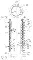
- FIG. 2a this is shown in the exemplary embodiment shown internal stationary part 26 a cylinder sleeve section 30 with a through hole 31 and an outward radial flange 32.
- the wall of the cylinder sleeve section 30 of the stationary part 26 are parallel to the cylinder axis, the corresponds to the axis of rotation A if the connecting device 20 in a Pump machine 10 is mounted, axial sections 33 of connecting lines 34 provided, which open into radial sections 35.
- connecting pieces 36 On the axial Sections 33 are connected to connecting pieces 36, which differ from one extend axially away from the lower end face 37 of the stationary part 26 and to which the fluid lines 25 attached to the machine frame 11 are connected can be.
- the axial sections 33 are the Connection lines 34 and the connecting piece 36 distributed circumferentially arranged in the sleeve wall of the stationary part 26.
- the radial sections 35 of the connecting lines 34 which in the outer peripheral surface of the Cylinder sleeve section 30 open, are against each other in the axial direction staggered.
- the outer rotating part 28 has a cylinder sleeve section 37 and an inward radial flange 38.
- the axial length of the cylinder sleeve section 37 of the rotating part 28 corresponds to that axial length of the cylinder sleeve section 30 of the stationary part 26, while the outer circumference of the inner stationary part 26 is smaller is the inside circumference of the cylinder sleeve portion 37 of the outside Rotating part 28, so that between the cylinder sleeve sections 30, 37 an annular channel space 39 is formed, which at its axial ends of the radial flanges 32, 38 is limited.
- the radial through openings 40 in the cylinder sleeve section 37 of the Rotating part 28 are with the radial sections 35 of the connecting lines 34 in the inner stationary part 26 aligned in the axial direction so that each have a radial section 35 of one of the connecting lines 34 with a radial through opening 40, that is to say with a connecting piece 41 lie in a plane perpendicular to the cylinder axis.
- sealing rings 42 for. B. Simmerings or other sealing rings suitable as high vacuum seals, in spaced and aligned such that each pair of fixed and circumferential connecting lines 34, 41 an annular channel 43 is assigned.
- the connecting device 20 thus enables a rotational position-independent permanent connection of fixed fluid lines 25 with about an axis of rotation A rotating fluid lines 19 via the corresponding Connection lines 34 in the stationary part 26, the ring channels 43 and the circumferential connecting lines or connecting pieces 41 in the rotating part 28.
- the internal part instead of the described function of the internal part as stationary Part 26 and the outer part as a rotating part 28, it is also possible to use the external part as a stationary part while the inside part turns. Furthermore, it is also possible in the outside Provide part of axial bores together with radial bores form appropriate connecting lines. If the through hole 31 of the cylindrical sleeve section 30 of the internal stationary Part 26 is not completely needed for other purposes, it is still possible, the connecting lines 34 through radial through openings to form, then connected to the corresponding connection lines can be.
- the arrangement of the radial flanges 32, 38 on the inside and outside Parts can be varied in different ways. It is particularly conceivable at both axial ends of the inner part to provide radial flanges that have different diameters, while the outer part consists only of a cylinder sleeve section exists, the inside diameter of the outside diameter of the corresponds smaller radial flange, so that when the outer part on the inner part is slid on, it is attached to the front of the radial flange larger diameter with one end while it is in the area its other end with its inner circumference on the outer circumference of the other radial flange abuts the other end of the inner part.
- each ring channel 43 has several stationary connecting lines 34 and / or several circumferential connecting pieces 41 are assigned if, for example in the case of a pump machine 10, the assignment the pump heads 15 to the vacuum pumps 23 varies or Pump power of the vacuum pump 23 is increased.
- Each pump head 15 is always the same vacuum pump 23 and assigned the same gas supply device.
- the connecting device according to the invention for connecting stationary Fluid lines 25 with fluid lines running around an axis of rotation A. 19 enables the creation of a high oil-free vacuum in to be evacuated, in the example shown in lamp bulbs 17 because of oils and other sealants and lubricants between sealant and Guide surfaces can be dispensed with.
- the manufacturing company can therefore be continued first because of the faulty lamp bulb generating pump head 15 can be specifically switched off, ie specifically not used until the next maintenance interruption becomes.
- the use of the connecting device according to the invention on a Pump machine described thus increases its productivity, because Downtimes are shortened and necessary repair work is made easier Troubleshooting can be simplified and accelerated.
Landscapes
- Engineering & Computer Science (AREA)
- General Engineering & Computer Science (AREA)
- Mechanical Engineering (AREA)
- Joints Allowing Movement (AREA)
- Quick-Acting Or Multi-Walled Pipe Joints (AREA)
Abstract
Description
Claims (8)
- Verbindungsvorrichtung zur Verbindung zumindest einer stationären Fluidleitung (25) mit zumindest einer relativ dazu bewegbaren Fluidleitung (19), die eine Umlaufbewegung um eine Drehachse (A) ausführen kann, miteinem koaxial zur Drehachse (A) angeordneten stationären Teil (26), in dem zumindest eine mit der stationären Fluidleitung (25) verbindbare stationäre Anschlußleitung (34) vorgesehen ist,einem koaxial zur Drehachse (A) und zum stationären Teil (26) angeordneten Drehteil (28), in dem zumindest eine mit diesem umlaufende Anschlußleitung (41) vorgesehen ist, die mit der bewegbaren Fluidleitung (19) verbindbar ist, undzumindest einem Ringkanal (43) zwischen dem stationären Teil (26) und dem Drehteil (28), in den die stationäre und die umlaufende Anschlußleitung (34, 41) münden.
- Verbindungsvorrichtung nach Anspruch 1, dadurch gekennzeichnet, daß eine Vielzahl von stationären Anschlußleitungen (34) im stationären Teil (26) und eine Vielzahl von umlaufenden Anschlußleitungen (41) im Drehteil (28) vorgesehen sind.
- Verbindungsvorrichtung nach Anspruch 2, dadurch gekennzeichnet, daß jede der stationären Anschlußleitungen (34) über einen zugeordneten Ringkanal (43) mit einer der umlaufenden Anschlußleitungen (41) verbunden ist.
- Verbindungsvorrichtung nach Anspruch 1, 2 oder 3, dadurch gekennzeichnet, daß zwischen dem stationären Teil (26) und dem Drehteil (28) ein vorzugsweise zylindrischer Ringkanalraum (39) vorgesehen ist, in dem einzelne Ringkanäle (43) durch Dichtringe (42) von einander getrennt sind.
- Verbindungsvorrichtung nach Anspruch 4, dadurch gekennzeichnet, daß der Ringkanalraum (39) an seinen axialen Enden durch Radialflansche (32, 38) begrenzt wird, von denen der eine am stationären Teil (26) und der andere am Drehteil (38) vorgesehen ist.
- Verbindungsvorrichtung nach Anspruch 4 oder 5, dadurch gekennzeichnet, daß zwischen den die Ringkanäle (43) begrenzenden Dichtringen (42) Distanzringe als Abstandshalter vorgesehen sind.
- Verbindungsvorrichtung nach einem der vorstehenden Ansprüche, dadurch gekennzeichnet, daß die Anschlußleitungen (34) im radial innenliegenden, hülsenartig ausgebildeten Teil (26), also im stationären Teil oder im Drehteil, sich axial erstreckende Abschnitte (33) in einer Umfangswand des radial innenliegenden Teils (26) aufweisen, die jeweils mit einem in den zugeordneten Ringkanal (43) mündenden radialen Abschnitt (35) kommunizieren.
- Verbindungsvorrichtung nach Anspruch 7, dadurch gekennzeichnet, daß alle sich axial erstreckenden Abschnitte (33) der Anschlußleitungen (34) im radial innenliegenden Teil (26) sich vom selben axialen Ende des radial innenliegenden Teils (26) aus zu den zugeordneten radialen Abschnitten (35) erstrecken.
Applications Claiming Priority (2)
| Application Number | Priority Date | Filing Date | Title |
|---|---|---|---|
| DE19934032 | 1999-07-21 | ||
| DE19934032A DE19934032A1 (de) | 1999-07-21 | 1999-07-21 | Verbindungsvorrichtung |
Publications (2)
| Publication Number | Publication Date |
|---|---|
| EP1070900A2 true EP1070900A2 (de) | 2001-01-24 |
| EP1070900A3 EP1070900A3 (de) | 2003-01-15 |
Family
ID=7915436
Family Applications (1)
| Application Number | Title | Priority Date | Filing Date |
|---|---|---|---|
| EP00114784A Withdrawn EP1070900A3 (de) | 1999-07-21 | 2000-07-10 | Verbindungsvorrichtung |
Country Status (3)
| Country | Link |
|---|---|
| EP (1) | EP1070900A3 (de) |
| DE (1) | DE19934032A1 (de) |
| HU (1) | HUP0002798A2 (de) |
Cited By (1)
| Publication number | Priority date | Publication date | Assignee | Title |
|---|---|---|---|---|
| EP1498654A1 (de) * | 2003-07-15 | 2005-01-19 | Schott Ag | Vorrichtung zur Behandlung von Werkstücken |
Family Cites Families (9)
| Publication number | Priority date | Publication date | Assignee | Title |
|---|---|---|---|---|
| AT103078B (de) * | 1924-03-18 | 1926-04-10 | Hans Gottwald | Vorrichtung zum Auspumpen von Glühlampen. |
| US2025579A (en) * | 1934-10-12 | 1935-12-24 | Gen Electric | Exhausting and gas-filling machine |
| DE926170C (de) * | 1952-09-05 | 1955-04-07 | Westinghouse Bremsen Ges M B H | Anschluss von Druckmittelkanaelen bei Rotoren |
| DE930942C (de) * | 1953-06-21 | 1955-07-28 | Pintsch Licht G M B H | Schliffplatte fuer Vakuumapparate, insbesondere fuer Pumpautomaten |
| US3950017A (en) * | 1974-04-29 | 1976-04-13 | United Technologies Corporation | Leakproof connection for polyethylene tubing |
| US4558890A (en) * | 1983-02-28 | 1985-12-17 | Pickle Creek Mfg., Inc. | Multi-port hydraulic swivel |
| DE3442362A1 (de) * | 1984-11-20 | 1986-05-22 | Patent-Treuhand-Gesellschaft für elektrische Glühlampen mbH, 8000 München | Vorrichtung zur herstellung zeitlich aufeinanderfolgender verbindungen zwischen den hohlraeumen von lampenglaskolben und druckquellen fuer gase und/oder vakuumquellen |
| DE9016212U1 (de) * | 1990-11-29 | 1991-03-21 | Schreiter, Eberhard, O-6218 Bad Salzungen | Einrichtung zur Überleitung von Druckmedien von einem feststehenden Gehäuse auf eine rotierende Welle |
| US5810034A (en) * | 1996-11-13 | 1998-09-22 | V-Tek Incorporated | Balanced rotary air manifold |
-
1999
- 1999-07-21 DE DE19934032A patent/DE19934032A1/de not_active Ceased
-
2000
- 2000-07-10 EP EP00114784A patent/EP1070900A3/de not_active Withdrawn
- 2000-07-20 HU HU0002798A patent/HUP0002798A2/hu unknown
Cited By (1)
| Publication number | Priority date | Publication date | Assignee | Title |
|---|---|---|---|---|
| EP1498654A1 (de) * | 2003-07-15 | 2005-01-19 | Schott Ag | Vorrichtung zur Behandlung von Werkstücken |
Also Published As
| Publication number | Publication date |
|---|---|
| HUP0002798A2 (en) | 2001-03-28 |
| HU0002798D0 (en) | 2000-09-28 |
| EP1070900A3 (de) | 2003-01-15 |
| DE19934032A1 (de) | 2001-02-01 |
Similar Documents
| Publication | Publication Date | Title |
|---|---|---|
| DE3320699C2 (de) | Vorrichtung zum Verändern des Leitschaufelwinkels bei axialen Strömungsmaschinen | |
| DE60101537T2 (de) | Nockenmechanismus mit Kreuzrollenlager | |
| EP1261820A1 (de) | Labyrinthdichtung zwischen drehbaren bauteilen | |
| EP1526316B1 (de) | Radiale Drehdurchführung | |
| WO2005063598A2 (de) | Rotationsträger mit elastischer verbindungseinrichtung zum einbau elektrischer maschinen in rohre | |
| EP1125772A2 (de) | Reifenfüllstation und Verfahren zur Reifenfüllung | |
| WO2021185542A1 (de) | Flüssigkeitsgekühlten rotor für einen elektromechanischen energiewandler | |
| WO2020221489A1 (de) | GLEITRINGDICHTUNGSANORDNUNG, INSBESONDERE FÜR HEIßE MEDIEN, SOWIE PUMPENANORDNUNG | |
| DE9313310U1 (de) | Werkzeugwechseleinrichtung für Manipulatoren | |
| DE102011000242B4 (de) | Antriebsmotor mit Drehdurchführung | |
| EP4062078B1 (de) | Lageranordnung und verfahren zum montieren einer solchen | |
| EP3801977B1 (de) | Wechselvorrichtung für rundschalttische | |
| WO2012055734A2 (de) | Vakuumpumpe | |
| DE102010018817A1 (de) | Transportvorrichtung für eine Maschine zur Herstellung von stabförmigen Produkten der Tabak verarbeitenden Industrie | |
| DE10329191A1 (de) | Drehdurchführung | |
| DE102008064456A1 (de) | Servolenkungsvorrichtung und deren Herstellungsverfahren | |
| DE3119807C2 (de) | Rotationskolbenmaschine | |
| EP2145717A1 (de) | Kammeranordnung für eine Elektronenstrahlbearbeitungsvorrichtung mit einem Schlitten und einer drehbaren Scheibe | |
| DE19934032A1 (de) | Verbindungsvorrichtung | |
| DE3137101C2 (de) | ||
| DE29913996U1 (de) | Getriebe | |
| DE102012104804A1 (de) | Verdrängerpumpe | |
| DE10332010B4 (de) | Drehdurchführung | |
| DE2818664C2 (de) | Dichtungsanordnung für eine Wellendurchführung | |
| DE202010012138U1 (de) | Zellenradschleuse |
Legal Events
| Date | Code | Title | Description |
|---|---|---|---|
| PUAI | Public reference made under article 153(3) epc to a published international application that has entered the european phase |
Free format text: ORIGINAL CODE: 0009012 |
|
| AK | Designated contracting states |
Kind code of ref document: A2 Designated state(s): AT BE CH CY DE DK ES FI FR GB GR IE IT LI LU MC NL PT SE |
|
| AX | Request for extension of the european patent |
Free format text: AL;LT;LV;MK;RO;SI |
|
| PUAL | Search report despatched |
Free format text: ORIGINAL CODE: 0009013 |
|
| AK | Designated contracting states |
Kind code of ref document: A3 Designated state(s): AT BE CH CY DE DK ES FI FR GB GR IE IT LI LU MC NL PT SE |
|
| AX | Request for extension of the european patent |
Free format text: AL;LT;LV;MK;RO;SI |
|
| STAA | Information on the status of an ep patent application or granted ep patent |
Free format text: STATUS: THE APPLICATION IS DEEMED TO BE WITHDRAWN |
|
| 18D | Application deemed to be withdrawn |
Effective date: 20030201 |
|
| REG | Reference to a national code |
Ref country code: DE Ref legal event code: 8566 |