EP1069863B1 - Ligationsband mit abgerundeten kanten und verfahren zur dessen herstellung - Google Patents
Ligationsband mit abgerundeten kanten und verfahren zur dessen herstellung Download PDFInfo
- Publication number
- EP1069863B1 EP1069863B1 EP99916300A EP99916300A EP1069863B1 EP 1069863 B1 EP1069863 B1 EP 1069863B1 EP 99916300 A EP99916300 A EP 99916300A EP 99916300 A EP99916300 A EP 99916300A EP 1069863 B1 EP1069863 B1 EP 1069863B1
- Authority
- EP
- European Patent Office
- Prior art keywords
- band
- ligating
- tissue
- elastic band
- ligating band
- Prior art date
- Legal status (The legal status is an assumption and is not a legal conclusion. Google has not performed a legal analysis and makes no representation as to the accuracy of the status listed.)
- Expired - Lifetime
Links
Images


Classifications
-
- A—HUMAN NECESSITIES
- A61—MEDICAL OR VETERINARY SCIENCE; HYGIENE
- A61B—DIAGNOSIS; SURGERY; IDENTIFICATION
- A61B17/00—Surgical instruments, devices or methods
- A61B17/12—Surgical instruments, devices or methods for ligaturing or otherwise compressing tubular parts of the body, e.g. blood vessels or umbilical cord
- A61B17/12009—Implements for ligaturing other than by clamps or clips, e.g. using a loop with a slip knot
- A61B17/12013—Implements for ligaturing other than by clamps or clips, e.g. using a loop with a slip knot for use in minimally invasive surgery, e.g. endoscopic surgery
-
- A—HUMAN NECESSITIES
- A61—MEDICAL OR VETERINARY SCIENCE; HYGIENE
- A61B—DIAGNOSIS; SURGERY; IDENTIFICATION
- A61B17/00—Surgical instruments, devices or methods
- A61B17/12—Surgical instruments, devices or methods for ligaturing or otherwise compressing tubular parts of the body, e.g. blood vessels or umbilical cord
- A61B17/12009—Implements for ligaturing other than by clamps or clips, e.g. using a loop with a slip knot
- A61B2017/12018—Elastic band ligators
Definitions
- the invention relates generally to the field of tissue ligation, and more particularly to an improved ligating band and a method of making the ligating band.
- Physicians have used elastic ligating bands to treat lesions, including internal hemorrhoids and mucositis and for performing mechanical hemostasis.
- the object of ligation is to position a ligating band over the targeted lesion or blood vessel section by stretching the band beyond its undeformed diameter drawing the tissue to be ligated within the band and then releasing the band so that it contracts, applying inward pressure on the section of tissue caught within the band.
- the effect of the inward pressure applied by the band is to stop all circulation through the targeted tissue, thereby causing the tissue to die.
- the body then sloughs off the dead tissue or the dead tissue may be aspirated into an endoscope or a similar device.
- Ligating bands are typically dispensed using ligating band dispensing devices which include cylindrical support surfaces over which elastic ligating bands are stretched.
- the cylindrical support surfaces are typically attached to the distal end of an endoscope which is advanced into the body to a target area. A user then applies suction through the endoscope to draw the tissue to be ligated into the cylindrical support surface and then releases a ligating band to contract around the tissue.
- Some ligating band dispensers use trigger lines received in slots at the distal end of a cylindrical support to roll ligating bands toward, and eventually off, the distal end of the support.
- a problem encountered with such devices when dispensing prior ligating bands is the bands may sometimes slide, rather than roll, along the cylindrical support.
- a band which slides, rather than rolls, may tend to push the trigger line ahead of it. This is disadvantageous because the trigger line may be pushed out of its slot in the distal rim of the cylindrical support, leaving a band with no trigger line attached.
- Ligating bands are often made by extruding an elastic compound through a tubular die. Then tube is then cut transversely to form the bands. As a result of this process, the bands have sharp edges along both the inner and the outer diameter surfaces. Such sharp edges may cause the bands to disadvantageously slide, rather than roll, when being dispensed from devices employing a trigger line.
- Elastic rings are known from US Patent 1,683,119 to Ziegler, GB 649 226 A to Montgomery and U.S. Patent 5,624,453 to Ahmed.
- a problem inherent with the type of ligating bands typically used with the above-described devices is that the bands have a tendency to slip off the targeted tissue before the tissue is completely ligated.
- tissue contained within a ligating band is effectively "pinched" by the ligating band, creating an outward pressure on the band.
- the bulb-shaped projection of tissue which has been drawn under suction into the lumen of a cylindrical support surface is pulled away from the surrounding tissue creating tension within the projection which draws the tissue of the projection back toward the its natural position.
- the tissue is urged to slip out of the ligating band as the band contracts.
- blood and fluid within the body can make the surface of the targeted tissue slick, thereby decreasing the coefficient of friction between the ligating band and the targeted tissue.
- the targeted tissue is an active blood vessel the "pulsing" effect of blood moving through the vessel can cause the ligating band to slip off of the targeted tissue.
- a ligating band which rolls, rather than slides, as it moves toward the distal end of the dispenser housing in trigger line-type dispensers. Also what is needed is a ligating band which remains in place once dispensed onto the target tissue.
- the present invention is directed to an improved elastic band for ligating tissue within a living body comprising a central opening defining an axis and having a first curved edge formed between a first surface extending substantially parallel to the axis and a second surface extending substantially perpendicular to the axis.
- a method of ligating tissue within a living body using such a ligating band comprises the steps of positioning the elastic band, which has been stretched to increase the size of a central opening extending therethrough, adjacent to a portion of tissue to be ligated. The tissue to be ligated is then drawn through the central opening of the elastic band and the elastic band is released so that the size of the central opening decreases to grip the tissue received therein.
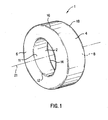
- ligating band 1 is formed as a ring comprising inner surface 2, outer surface 4, first side surface 6, second side surface 8 and central opening 11 through defining an axis 21.
- the ligating band 1 may be intentionally or accidentally twisted so that any of the surfaces 4, 6 and 8 becomes the inner surface 2.
- surfaces 2 and 6 meet at edge, or juncture, 12.
- surfaces 2 and 8 meet at edge 14, surfaces 4 and 6 meet at edge 16, and surfaces 4 and 8 meet at edge 18.
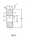
- ligating band 1 has an inner diameter ID, an outer diameter OD, and an axial thickness AT.
- the inner diameter ID of ligating band 1 is between 0.178 and 0.216 centimeters (0.07 and 0.085 inches) and is more prelerably between 0.178 and 0.203 centimeters (0.07 and 0.08 inches) and is most preferably approximately 0,19 centimeters (0.075 inches).
- the outer diameter OD of the band is preferably between 0.558 and 0.610 centimeters (0.22 and 0.24 inches), while the band preferably has an axial thickness AT of approximately 0.178 and 0.216 centimeters (0.07 and 0.085 inches), is more preferably between 0.178 and 0.203 centimeters (0.07 inches and 0.08 inches) and is most preferably approximately 0.19 centimeters (0.075 inches).
- a ligating band may easily be rolled across the cylindrical support surface so that the ID surface becomes the OD surface, etc. and that it may therefore be preferable to make the thickness of the band 1 in each direction between 0,178 and 0,216 centimeters (0.07 and 0.085 inches), more preferably between 0.178 and 0.203 centimeters (0.07 inches and 0.08) inches and most preferably approximately 0,19 centimeters (0.075 inches) so that the cross-section of the band 1 is substantially square (except for the rounded edges).
- inner surface 2 is preferably substantially parallel to outer surface 4, while first side surface 6 is preferable substantially parallel to second side surface 8, so that ligating band 1 has an axial cross-section which is substantially rectangular.
- surfaces 2 and 4, or 6 and 8. respectively may be non-parallel to each other so that ligating band 1 has an axial cross-section which is a trapezoid, an irregular quadrilateral, etc.
- ligating band 1 may have only three surfaces forming a triangular cross-section.
- one or both of the surfaces 6 and 8 themselves may be rounded such that surfaces 2, 4, 6 and 8 form a continuous surface having an elliptical or other correspondingly curved cross-section.
- edges 12, 14, 16 and 18 of ligating band 1 are curved, or radiused, so that ligating band 1 may roll when being advanced along a cylindrical support in a ligating band dispenser. Curved edges 12, 14, 16 and 18 may thus avoid the tendency to slide, rather than roll, exhibited by prior ligating bands having sharp edges.
- the radius of curvature of curved edges 12, 14, 16 and 18 is approximately 0,038 cm (0.015 in) for a band having the preferred dimensions described above. In other embodiments of the invention, the radius of curvature of curved edges 12, 14, 16 and 18 may have other appropriate magnitudes apparent to those skilled in the art.
- ligating band 1 is made of from latex.
- ligating band 1 may be made of polyisoprene or any of a variety of other elastic materials.
- Ligating band 1 is preferably formed by any of a variety of known molding processes such as those in which a material is injected into a mold and cured to form an elastic band of the desired shape and size. In other embodiments of the invention, other band formation techniques known in the art may be employed.
- ligating band 1 is provided with texturing 50, of the type described in US. Patent No. 5,976,158. Texturing 50 provides enhanced gripping of the tissue held by ligating band 1.
- texturing 50 is provided on each surface 2,4,6 and 8.
- texturing 50 may be provided on all or some of the surfaces of any of the improved ligating band 1 embodiments described herein.
- surfaces 6, or 8 may be rounded, as described above, reducing the distinction between the various surfaces.
- this distinction between the various surfaces is unimportant so long as the surface of the ligating band 1 which is in contact with the tissue to be ligated includes texturing as described herein.
- the texturing 50 is preferably comprised of a pattern of raised bumps which are formed as cylindrical stems 52 and hemispherical caps 54.
- texturing 50 may comprise other types of discontinuities such as depressions, or both raised bumps and depressions.
- Alternate forms of texturing 50 can employ one or more of a variety of different shapes.
- the texturing 50 is preferably evenly distributed on any surface 2, 4, 6 or 8 to which the texturing 50 is applied.
- the texturing 50 may preferably be applied to the ligating band 1 via a molding process, thereby making the texturing 50 an integral part of the structure of the ligating band 1.
- the texturing 50 is formed from the same material as the band itself.
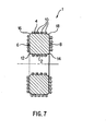
- texturing 50 is applied to the ligating band 1 so that the raised bumps on a first side 18 of the inner surface 2 and the raised bumps on a second side 20 thereof combine to form an interlocking pattern.
- the raised bumps on both the first side 19 and the second side 20 hold the tissue to be ligated by the ligating band 1 more securely in place when the ligating band 1 applies inward pressure on the tissue with the bumps from one side forcing the tissue into a gap between the bumps on the other side.
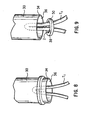
- Fig. 6 although it is preferable to have texturing 50 on all surfaces 2, 4, 6 and 8 of the ligating band 1, it is not necessarily required so long as the user ensures that the surface including the texturing 50 remains, through the placement procedure, positioned so that it contacts the surface to be ligated. In use, the tissue to be ligated is drawn up within central opening 11. Thus, only texturing 50 placed on the surface positioned at inner surface 2 is designed to come in contact with the tissue to be ligated.
- texturing 50 be provided on each of surfaces 4. 6 and 8 in addition to inner surface 2 as the ligating band 1 may "roll" after during the dispensing procedure or after being dispensed onto the tissue to be ligated.
- a physician cannot be certain that the ligating band 1 will not ultimately be turned “inside out” on the tissue to be ligated such that outer surface 4, for example, comes in contact with the tissue to be ligated rather than the inner surface 2.
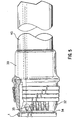
- a physician first loads the band onto cylindrical support 32 of a ligating band dispenser 30, such as a trigger line ligating dispenser described above or such as a dispenser described in U.S. Patent No. 5.356,416, so that the inner diameter ID of the ligating band 1 is substantially greater that its natural, pre-deformed inner diameter ID.
- a ligating band dispenser 30 such as a trigger line ligating dispenser described above or such as a dispenser described in U.S. Patent No. 5.356,416, so that the inner diameter ID of the ligating band 1 is substantially greater that its natural, pre-deformed inner diameter ID.
- the physician positions distal end 34 having distal aperture 36 of the ligating band dispenser 30 adjacent to a first portion 38 of tissue T1.
- the first portion 38 is then drawn into the distal aperture 36, preferably under suction.
- the first section of tissue T1 may be drawn within the distal aperture 36 by mechanical means, such as a forceps, jaws, clamp, or the like (not shown).
- the physician then triggers the ligating band dispenser 30 to release one or more ligating bands 1 off of distal end 34 over the targeted first portion 38 of tissue T1.
- the inner diameter ID of the ligating band 1 suddenly decreases as the ligating band 1 seeks to return to its pre-deformed state.
- the texturing 50 on the inner surface 2 of the ligating band 1 engages first portion 38 of tissue T1 and exerts inward pressure on the tissue.
- the texturing provides additional grip for engaging tissue T1.
- the pressure on the tissue stops all circulation through the targeted tissue T1, thereby causing first portion 38 to die.
- the body then sloughs off the dead tissue 38.
- the dead tissue 38 may be removed by mechanical means and aspirated into an endoscope, the ligating band dispenser 30, or a similar device.
- the texturing 50 while the texturing 50 on the inner surface 2 of the ligating band 1 is exerting inward pressure on the tissue 36.
- the texturing 50 restricts the movement of the ligating band 1 over the tissue 36.
- the ligating band 1 of the present invention is less likely than prior art ligating bands to be displaced from the targeted tissue portion 38 in response to outward pressures caused by the "pinching" of the targeted tissue portion 38 or by the movement of blood or other fluid through the targeted tissue T1.
- the texturing 50 on the inner surface 2 of the ligating band 1 is exerting inward pressure on tissue portion 38.
- the texturing 50 on the first side 18 of the inner surface 2 remotely engages the texturing 50 on the second side 20 of the inner surface 2 through tissue portion 38 to form an interlocking pattern.
- the texturing 50 more effectively restricts the movement of the ligating band 1 relative to tissue portion 38.
Landscapes
- Health & Medical Sciences (AREA)
- Surgery (AREA)
- Life Sciences & Earth Sciences (AREA)
- Heart & Thoracic Surgery (AREA)
- Nuclear Medicine, Radiotherapy & Molecular Imaging (AREA)
- Vascular Medicine (AREA)
- Engineering & Computer Science (AREA)
- Biomedical Technology (AREA)
- Reproductive Health (AREA)
- Medical Informatics (AREA)
- Molecular Biology (AREA)
- Animal Behavior & Ethology (AREA)
- General Health & Medical Sciences (AREA)
- Public Health (AREA)
- Veterinary Medicine (AREA)
- Surgical Instruments (AREA)
Claims (10)
- Elastisches Band (1) zum Abbinden von Gewebe innerhalb eines lebenden Körpers, das eine zentrale Öffnung aufweist, welche eine Achse (21) vorgibt, dadurch gekennzeichnet, dass die zentrale Öffnung im Ligationsband eine erste gekrümmte Kante (12) enthält, die zwischen einer ersten Oberfläche (2), welche sich im Wesentlichen parallel zur Achse (21) erstreckt, und einer zweiten Oberfläche (6), die sich im Wesentlichen senkrecht zur Achse (21) erstreckt, gebildet wird.
- Elastisches Band (1) nach Anspruch 1, worin die erste Oberfläche (2) eine Vielzahl von Vorsprüngen (10, 110) enthält, die darin gebildet werden.
- Elastisches Band (1) nach Anspruch 1, worin die erste Oberfläche eine Vielzahl von Vertiefungen enthält, die darin gebildet werden.
- Elastisches Band (1) nach Anspruch 1, worin das elastische Band (1) im Wesentlichen in der Gestalt eines Zylinders geformt wird, wobei das Band ferner eine zweite gekrümmte Kante (14) aufweist, die zwischen der ersten Oberfläche (2) und einer dritten Oberfläche (8), die sich im Wesentlichen senkrecht zur Achse (21) erstreckt, gebildet wird, eine dritte gekrümmte Kante (16), die zwischen einer vierten Oberfläche (4), die sich im Wesentlichen parallel zur Achse (21) erstreckt, und der zweiten Oberfläche (6) gebildet wird, und eine vierte gekrümmte Kante (18), die zwischen der dritten Oberfläche (8) und der vierten Oberfläche (4) gebildet wird.
- Elastisches Band (1) nach Anspruch 4, worin wenigstens eine der ersten (2) der zweiten (6), dritten (8) und vierten (4) Oberflächen eine Vielzahl von Vorsprüngen (10, 110) enthält, die sich davon erstrecken.
- Elastisches Band (1) nach Anspruch 4, worin wenigstens eine der ersten (2), zweiten (6), dritten (8) und vierten (4) Oberflächen eine Vielzahl von Einbuchtungen enthält, die sich darin ausbilden.
- Elastisches Band (1) nach Anspruch 1, worin ein Querschnitt des Bandes (1) in einer Richtung im Wesentlichen parallel zur Achse (21) im Wesentlichen rechteckig ist.
- Verfahren zur Herstellung eines elastischen Bandes (1) zum Abbinden von Gewebe innerhalb eines lebenden Körpers, umfassend die Schritte von:Injizieren von elastischem Material in eine Gießform, die das elastische Band vorgibt, wobei das elastische Band (1) eine zentrale Öffnung aufweist, welche eine Achse (21) vorgibt, wobei die zentrale Öffnung im Ligationsband eine erste gekrümmte Kante (12) enthält, die zwischen einer ersten Oberfläche (2), die sich im Wesentlichen parallel zur Achse (21) erstreckt, und einer zweiten Oberfläche (6), die sich im Wesentlichen senkrecht zur Achse (21) erstreckt, gebildet wird; undAushärten des Materials.
- Verfahren nach Anspruch 8, worin eine Vielzahl von Einbuchtungen in einer Oberfläche der Gießform gebildet werden, die der ersten Oberfläche (2) des elastischen Bandes (1) entspricht, so dass das elastische Band (1) eine Vielzahl von Vorsprüngen (10, 110) aufweist, die sich davon erstrecken.
- Verfahren nach Anspruch 8, worin sich eine Vielzahl von Vorsprüngen (10, 110) von einer Oberfläche der Gießform erstrecken, die einer ersten Oberfläche (2) des elastischen Bandes (1) entspricht, so dass das elastische Band (10) eine Vielzahl von Einbuchtungen darauf enthält.
Applications Claiming Priority (3)
| Application Number | Priority Date | Filing Date | Title |
|---|---|---|---|
| US09/056,575 US5972009A (en) | 1998-04-07 | 1998-04-07 | Ligating band with rounded edges and method of use of same |
| US56575 | 1998-04-07 | ||
| PCT/US1999/007264 WO1999051150A1 (en) | 1998-04-07 | 1999-04-02 | Ligating band with rounded edges and method of use of same |
Publications (2)
| Publication Number | Publication Date |
|---|---|
| EP1069863A1 EP1069863A1 (de) | 2001-01-24 |
| EP1069863B1 true EP1069863B1 (de) | 2005-12-07 |
Family
ID=22005332
Family Applications (1)
| Application Number | Title | Priority Date | Filing Date |
|---|---|---|---|
| EP99916300A Expired - Lifetime EP1069863B1 (de) | 1998-04-07 | 1999-04-02 | Ligationsband mit abgerundeten kanten und verfahren zur dessen herstellung |
Country Status (7)
| Country | Link |
|---|---|
| US (2) | US5972009A (de) |
| EP (1) | EP1069863B1 (de) |
| JP (1) | JP2002510518A (de) |
| AU (1) | AU3465099A (de) |
| CA (1) | CA2326830A1 (de) |
| DE (1) | DE69928785T2 (de) |
| WO (1) | WO1999051150A1 (de) |
Families Citing this family (49)
| Publication number | Priority date | Publication date | Assignee | Title |
|---|---|---|---|---|
| US5976158A (en) | 1997-06-02 | 1999-11-02 | Boston Scientific Corporation | Method of using a textured ligating band |
| US5972009A (en) * | 1998-04-07 | 1999-10-26 | Boston Scientific Corporation | Ligating band with rounded edges and method of use of same |
| US6974466B2 (en) | 2000-12-06 | 2005-12-13 | Wilson-Cook Medical Inc. | Ligating band delivery apparatus |
| US20030050648A1 (en) | 2001-09-11 | 2003-03-13 | Spiration, Inc. | Removable lung reduction devices, systems, and methods |
| US6592594B2 (en) | 2001-10-25 | 2003-07-15 | Spiration, Inc. | Bronchial obstruction device deployment system and method |
| US6929637B2 (en) | 2002-02-21 | 2005-08-16 | Spiration, Inc. | Device and method for intra-bronchial provision of a therapeutic agent |
| US20030216769A1 (en) | 2002-05-17 | 2003-11-20 | Dillard David H. | Removable anchored lung volume reduction devices and methods |
| US20030181922A1 (en) | 2002-03-20 | 2003-09-25 | Spiration, Inc. | Removable anchored lung volume reduction devices and methods |
| US20040010209A1 (en) * | 2002-07-15 | 2004-01-15 | Spiration, Inc. | Device and method for measuring the diameter of an air passageway |
| US20040059263A1 (en) | 2002-09-24 | 2004-03-25 | Spiration, Inc. | Device and method for measuring the diameter of an air passageway |
| US7220186B1 (en) * | 2003-02-24 | 2007-05-22 | Burnham Steven M | Bowling ball insert providing finger tip gripping |
| US7100616B2 (en) | 2003-04-08 | 2006-09-05 | Spiration, Inc. | Bronchoscopic lung volume reduction method |
| US7533671B2 (en) | 2003-08-08 | 2009-05-19 | Spiration, Inc. | Bronchoscopic repair of air leaks in a lung |
| US7625387B2 (en) * | 2003-11-05 | 2009-12-01 | Applied Medical Resources Corporation | Suture securing device and method |
| WO2007004856A1 (es) * | 2005-07-05 | 2007-01-11 | Garcia Alonso Macias Parra, Annette | Dispositivo para ligar el cordón umbilical |
| US20070281271A1 (en) * | 2005-08-22 | 2007-12-06 | Odenkirchen Bernard W | Salivary duct constriction systems and devices |
| US9456811B2 (en) | 2005-08-24 | 2016-10-04 | Abbott Vascular Inc. | Vascular closure methods and apparatuses |
| US8758397B2 (en) | 2005-08-24 | 2014-06-24 | Abbott Vascular Inc. | Vascular closure methods and apparatuses |
| US8920442B2 (en) | 2005-08-24 | 2014-12-30 | Abbott Vascular Inc. | Vascular opening edge eversion methods and apparatuses |
| US20070060895A1 (en) | 2005-08-24 | 2007-03-15 | Sibbitt Wilmer L Jr | Vascular closure methods and apparatuses |
| US7691151B2 (en) | 2006-03-31 | 2010-04-06 | Spiration, Inc. | Articulable Anchor |
| JP5273980B2 (ja) * | 2007-10-01 | 2013-08-28 | オリンパスメディカルシステムズ株式会社 | 内視鏡用結紮具及び内視鏡結紮システム |
| US8043301B2 (en) | 2007-10-12 | 2011-10-25 | Spiration, Inc. | Valve loader method, system, and apparatus |
| JP5570993B2 (ja) | 2007-10-12 | 2014-08-13 | スピレーション インコーポレイテッド | 弁装填具の方法、システム、および装置 |
| US10149681B2 (en) * | 2007-10-23 | 2018-12-11 | Insightra Medical, Inc. | Devices and methods for securing tissue |
| US9125656B2 (en) * | 2007-10-23 | 2015-09-08 | Insightra Medical, Inc. | Devices and methods for securing tissue |
| USD638096S1 (en) * | 2009-06-03 | 2011-05-17 | Celgard Llc | Wafer-shaped hollow fiber module |
| US20110046640A1 (en) * | 2009-07-31 | 2011-02-24 | Miller David B | Tool to assist use of animal ligation device |
| USD666458S1 (en) | 2010-09-10 | 2012-09-04 | Seana L. Montgomery | Bowl with utensil retention feature |
| US9149276B2 (en) | 2011-03-21 | 2015-10-06 | Abbott Cardiovascular Systems, Inc. | Clip and deployment apparatus for tissue closure |
| US8795241B2 (en) | 2011-05-13 | 2014-08-05 | Spiration, Inc. | Deployment catheter |
| US9414822B2 (en) | 2011-05-19 | 2016-08-16 | Abbott Cardiovascular Systems, Inc. | Tissue eversion apparatus and tissue closure device and methods for use thereof |
| US9204782B2 (en) | 2011-10-27 | 2015-12-08 | Boston Scientific Scimed, Inc. | Mucosal resection device and related methods of use |
| US9155554B2 (en) | 2011-10-27 | 2015-10-13 | Boston Scientific Scimed, Inc. | Tissue resection bander and related methods of use |
| US8695838B1 (en) | 2012-06-06 | 2014-04-15 | Seana L. Montgomery | Bowl with utensil holder |
| USD763658S1 (en) * | 2012-09-26 | 2016-08-16 | Whirlpool Corporation | Colored medallion |
| DE202013100076U1 (de) * | 2013-01-08 | 2013-01-17 | Michael Maurus | Ligatorsystem mit Zwischenring zwischen den Ringbändern |
| US10105143B2 (en) * | 2013-06-05 | 2018-10-23 | Boston Scientific Scimed, Inc. | Cap with band deployment features |
| USD743382S1 (en) * | 2013-09-20 | 2015-11-17 | Panasonic Intellectual Property Management Co., Ltd. | Microphone |
| CN108712890A (zh) | 2015-12-07 | 2018-10-26 | 桑诺维私人有限公司 | 用于血管的压力响应性重塑的装置和方法 |
| US10667819B2 (en) | 2016-01-18 | 2020-06-02 | Insightra Medical, Inc. | Delivery assembly for resilient tissue clamp |
| USD822920S1 (en) * | 2016-01-18 | 2018-07-10 | Hyper Pet Llc | Pet toy |
| KR101806732B1 (ko) | 2016-08-25 | 2017-12-07 | 고려대학교 산학협력단 | 자궁경부 무력증에서 조산을 방지하기 위한 자궁경부 밴드 구조체 |
| US11497507B2 (en) | 2017-02-19 | 2022-11-15 | Orpheus Ventures, Llc | Systems and methods for closing portions of body tissue |
| US11871930B2 (en) | 2018-01-26 | 2024-01-16 | United States Endoscopy Group, Inc. | Anti-slip ligation bands |
| JP2020005871A (ja) * | 2018-07-06 | 2020-01-16 | 朝日インテック株式会社 | 体内留置デバイス |
| US20220160369A1 (en) * | 2020-11-23 | 2022-05-26 | IPC, LLC DBA PlatinumCode | Bilateral reversible venous tourniquet bands |
| USD1043264S1 (en) | 2021-09-02 | 2024-09-24 | Float Luv LLC | Beverage container holder |
| KR102701263B1 (ko) * | 2022-03-10 | 2024-08-29 | 가톨릭대학교 산학협력단 | 결찰밴드 |
Family Cites Families (24)
| Publication number | Priority date | Publication date | Assignee | Title |
|---|---|---|---|---|
| US1683119A (en) * | 1927-09-21 | 1928-09-04 | Charles E Ziegler | Umbilical clamp tool |
| GB649226A (en) * | 1947-11-10 | 1951-01-24 | Alan Yalden Montgomery | Improvements in or relating to rubber or like constricting rings for emasculating and detailing lambs and other animals |
| US3880166A (en) * | 1973-08-20 | 1975-04-29 | Thomas J Fogarty | Vessel occluder |
| GB1530282A (en) | 1975-07-22 | 1978-10-25 | Filshie G | Sexual sterilization devices |
| US4167188A (en) * | 1976-12-13 | 1979-09-11 | Lay Coy L | Surgical elastic band |
| US4485814A (en) | 1979-09-05 | 1984-12-04 | Yoon In B | One-piece compound elastic occluding member |
| US4548201A (en) * | 1982-04-20 | 1985-10-22 | Inbae Yoon | Elastic ligating ring clip |
| US4860746A (en) * | 1982-04-20 | 1989-08-29 | Inbae Yoon | Elastic surgical ring clip and ring loader |
| US4881939A (en) * | 1985-02-19 | 1989-11-21 | The Johns Hopkins University | Implantable helical cuff |
| US5074869A (en) * | 1988-09-26 | 1991-12-24 | Daicoff George R | Vascular occlusion device |
| US4938765A (en) * | 1989-06-22 | 1990-07-03 | Life Centers, Inc. | Surgical silicon loops |
| US5213749A (en) | 1991-07-31 | 1993-05-25 | Westinghouse Air Brake Company | Method of forming a rubber seal having a metallic insert |
| US5201900A (en) | 1992-02-27 | 1993-04-13 | Medical Scientific, Inc. | Bipolar surgical clip |
| US5356416A (en) | 1992-10-09 | 1994-10-18 | Boston Scientific Corporation | Combined multiple ligating band dispenser and sclerotherapy needle instrument |
| US5624453A (en) * | 1993-02-23 | 1997-04-29 | Wilson-Cook Medical, Inc. | Endoscopic ligating instrument |
| US5462559A (en) * | 1993-02-23 | 1995-10-31 | Ahmed; Munir | Endoscopic ligating instrument |
| JP2958219B2 (ja) * | 1993-08-20 | 1999-10-06 | 住友ベークライト株式会社 | 内視鏡的結紮用キット |
| US5398844A (en) | 1994-01-31 | 1995-03-21 | Boston Scientific Corporation | Multiple ligating band dispenser |
| US5578047A (en) * | 1994-08-16 | 1996-11-26 | Taylor; Jerry W. | Hemorrhoid removing device |
| DE19534323A1 (de) * | 1995-09-15 | 1997-03-20 | Aesculap Ag | Klemmring für einen chirurgischen Clip |
| US5752966A (en) * | 1997-03-07 | 1998-05-19 | Chang; David W. | Exovascular anastomotic device |
| US5976158A (en) * | 1997-06-02 | 1999-11-02 | Boston Scientific Corporation | Method of using a textured ligating band |
| JP3902290B2 (ja) * | 1997-06-19 | 2007-04-04 | ペンタックス株式会社 | 内視鏡用結紮具 |
| US5972009A (en) * | 1998-04-07 | 1999-10-26 | Boston Scientific Corporation | Ligating band with rounded edges and method of use of same |
-
1998
- 1998-04-07 US US09/056,575 patent/US5972009A/en not_active Expired - Lifetime
-
1999
- 1999-04-02 AU AU34650/99A patent/AU3465099A/en not_active Abandoned
- 1999-04-02 DE DE69928785T patent/DE69928785T2/de not_active Expired - Fee Related
- 1999-04-02 CA CA002326830A patent/CA2326830A1/en not_active Abandoned
- 1999-04-02 JP JP2000541926A patent/JP2002510518A/ja active Pending
- 1999-04-02 WO PCT/US1999/007264 patent/WO1999051150A1/en not_active Ceased
- 1999-04-02 EP EP99916300A patent/EP1069863B1/de not_active Expired - Lifetime
- 1999-10-08 US US09/645,987 patent/US6409737B1/en not_active Expired - Lifetime
Also Published As
| Publication number | Publication date |
|---|---|
| CA2326830A1 (en) | 1999-10-14 |
| DE69928785T2 (de) | 2006-07-06 |
| WO1999051150A1 (en) | 1999-10-14 |
| AU3465099A (en) | 1999-10-25 |
| US5972009A (en) | 1999-10-26 |
| DE69928785D1 (de) | 2006-01-12 |
| JP2002510518A (ja) | 2002-04-09 |
| EP1069863A1 (de) | 2001-01-24 |
| US6409737B1 (en) | 2002-06-25 |
Similar Documents
| Publication | Publication Date | Title |
|---|---|---|
| EP1069863B1 (de) | Ligationsband mit abgerundeten kanten und verfahren zur dessen herstellung | |
| US6613060B2 (en) | Textured ligating band | |
| US5853416A (en) | Distal end for ligating band dispenser | |
| US5441509A (en) | Vessel clips | |
| CA2158976C (en) | Telescoping serial elastic band ligator | |
| US5913865A (en) | Distal end for ligating band dispenser | |
| US20030229359A1 (en) | Ligating band dispenser with transverse ridge profile | |
| US6325809B1 (en) | Speedband intubation plug | |
| US12102326B2 (en) | Anti-slip ligation bands | |
| AU2003200075B2 (en) | Improved distal end for ligating band dispenser | |
| US8932306B1 (en) | Device and associated method for use in the treatment of hemorrhoids | |
| CA2563046C (en) | Improved distal end for ligating band dispenser |
Legal Events
| Date | Code | Title | Description |
|---|---|---|---|
| PUAI | Public reference made under article 153(3) epc to a published international application that has entered the european phase |
Free format text: ORIGINAL CODE: 0009012 |
|
| 17P | Request for examination filed |
Effective date: 20001106 |
|
| AK | Designated contracting states |
Kind code of ref document: A1 Designated state(s): BE DE FR GB IE NL |
|
| 17Q | First examination report despatched |
Effective date: 20040805 |
|
| GRAP | Despatch of communication of intention to grant a patent |
Free format text: ORIGINAL CODE: EPIDOSNIGR1 |
|
| RTI1 | Title (correction) |
Free format text: LIGATING BAND WITH ROUNDED EDGES AND ITS METHOD OF MANUFACTURE |
|
| GRAS | Grant fee paid |
Free format text: ORIGINAL CODE: EPIDOSNIGR3 |
|
| GRAA | (expected) grant |
Free format text: ORIGINAL CODE: 0009210 |
|
| AK | Designated contracting states |
Kind code of ref document: B1 Designated state(s): BE DE FR GB IE NL |
|
| PG25 | Lapsed in a contracting state [announced via postgrant information from national office to epo] |
Ref country code: BE Free format text: LAPSE BECAUSE OF FAILURE TO SUBMIT A TRANSLATION OF THE DESCRIPTION OR TO PAY THE FEE WITHIN THE PRESCRIBED TIME-LIMIT Effective date: 20051207 |
|
| REG | Reference to a national code |
Ref country code: GB Ref legal event code: FG4D |
|
| REG | Reference to a national code |
Ref country code: IE Ref legal event code: FG4D |
|
| REF | Corresponds to: |
Ref document number: 69928785 Country of ref document: DE Date of ref document: 20060112 Kind code of ref document: P |
|
| PGFP | Annual fee paid to national office [announced via postgrant information from national office to epo] |
Ref country code: FR Payment date: 20060403 Year of fee payment: 8 |
|
| ET | Fr: translation filed | ||
| PLBE | No opposition filed within time limit |
Free format text: ORIGINAL CODE: 0009261 |
|
| STAA | Information on the status of an ep patent application or granted ep patent |
Free format text: STATUS: NO OPPOSITION FILED WITHIN TIME LIMIT |
|
| 26N | No opposition filed |
Effective date: 20060908 |
|
| PG25 | Lapsed in a contracting state [announced via postgrant information from national office to epo] |
Ref country code: FR Free format text: LAPSE BECAUSE OF NON-PAYMENT OF DUE FEES Effective date: 20070430 |
|
| PGFP | Annual fee paid to national office [announced via postgrant information from national office to epo] |
Ref country code: GB Payment date: 20090312 Year of fee payment: 11 |
|
| PGFP | Annual fee paid to national office [announced via postgrant information from national office to epo] |
Ref country code: IE Payment date: 20090423 Year of fee payment: 11 |
|
| PGFP | Annual fee paid to national office [announced via postgrant information from national office to epo] |
Ref country code: NL Payment date: 20090409 Year of fee payment: 11 Ref country code: DE Payment date: 20090430 Year of fee payment: 11 |
|
| REG | Reference to a national code |
Ref country code: NL Ref legal event code: V1 Effective date: 20101101 |
|
| GBPC | Gb: european patent ceased through non-payment of renewal fee |
Effective date: 20100402 |
|
| REG | Reference to a national code |
Ref country code: IE Ref legal event code: MM4A |
|
| PG25 | Lapsed in a contracting state [announced via postgrant information from national office to epo] |
Ref country code: NL Free format text: LAPSE BECAUSE OF NON-PAYMENT OF DUE FEES Effective date: 20101101 Ref country code: IE Free format text: LAPSE BECAUSE OF NON-PAYMENT OF DUE FEES Effective date: 20100402 |
|
| PG25 | Lapsed in a contracting state [announced via postgrant information from national office to epo] |
Ref country code: DE Free format text: LAPSE BECAUSE OF NON-PAYMENT OF DUE FEES Effective date: 20101103 |
|
| PG25 | Lapsed in a contracting state [announced via postgrant information from national office to epo] |
Ref country code: GB Free format text: LAPSE BECAUSE OF NON-PAYMENT OF DUE FEES Effective date: 20100402 |