EP1069698A2 - Apparail et procédé d'aligner un pointeur pour commutation sans parasite - Google Patents
Apparail et procédé d'aligner un pointeur pour commutation sans parasite Download PDFInfo
- Publication number
- EP1069698A2 EP1069698A2 EP99121941A EP99121941A EP1069698A2 EP 1069698 A2 EP1069698 A2 EP 1069698A2 EP 99121941 A EP99121941 A EP 99121941A EP 99121941 A EP99121941 A EP 99121941A EP 1069698 A2 EP1069698 A2 EP 1069698A2
- Authority
- EP
- European Patent Office
- Prior art keywords
- signal
- payload
- pointer
- pointer value
- ahead
- Prior art date
- Legal status (The legal status is an assumption and is not a legal conclusion. Google has not performed a legal analysis and makes no representation as to the accuracy of the status listed.)
- Withdrawn
Links
- 238000000034 method Methods 0.000 title claims abstract description 30
- 239000000872 buffer Substances 0.000 claims abstract description 98
- 238000012545 processing Methods 0.000 claims abstract description 10
- 230000007246 mechanism Effects 0.000 claims abstract description 8
- RGNPBRKPHBKNKX-UHFFFAOYSA-N hexaflumuron Chemical group C1=C(Cl)C(OC(F)(F)C(F)F)=C(Cl)C=C1NC(=O)NC(=O)C1=C(F)C=CC=C1F RGNPBRKPHBKNKX-UHFFFAOYSA-N 0.000 claims description 36
- 238000004891 communication Methods 0.000 claims description 6
- 230000003466 anti-cipated effect Effects 0.000 claims description 3
- 230000008859 change Effects 0.000 description 7
- 230000009471 action Effects 0.000 description 6
- 238000010586 diagram Methods 0.000 description 6
- 230000008901 benefit Effects 0.000 description 4
- 239000000284 extract Substances 0.000 description 4
- 230000004044 response Effects 0.000 description 4
- 230000001934 delay Effects 0.000 description 3
- 230000003111 delayed effect Effects 0.000 description 2
- 238000012423 maintenance Methods 0.000 description 2
- 230000001360 synchronised effect Effects 0.000 description 2
- 238000013459 approach Methods 0.000 description 1
- 230000009977 dual effect Effects 0.000 description 1
- 230000008713 feedback mechanism Effects 0.000 description 1
- 230000004048 modification Effects 0.000 description 1
- 238000012986 modification Methods 0.000 description 1
- 230000003287 optical effect Effects 0.000 description 1
- 230000008569 process Effects 0.000 description 1
- 230000001172 regenerating effect Effects 0.000 description 1
- 230000008054 signal transmission Effects 0.000 description 1
- 238000012546 transfer Methods 0.000 description 1
Images
Classifications
-
- H—ELECTRICITY
- H04—ELECTRIC COMMUNICATION TECHNIQUE
- H04B—TRANSMISSION
- H04B10/00—Transmission systems employing electromagnetic waves other than radio-waves, e.g. infrared, visible or ultraviolet light, or employing corpuscular radiation, e.g. quantum communication
- H04B10/03—Arrangements for fault recovery
- H04B10/032—Arrangements for fault recovery using working and protection systems
-
- H—ELECTRICITY
- H04—ELECTRIC COMMUNICATION TECHNIQUE
- H04B—TRANSMISSION
- H04B1/00—Details of transmission systems, not covered by a single one of groups H04B3/00 - H04B13/00; Details of transmission systems not characterised by the medium used for transmission
- H04B1/74—Details of transmission systems, not covered by a single one of groups H04B3/00 - H04B13/00; Details of transmission systems not characterised by the medium used for transmission for increasing reliability, e.g. using redundant or spare channels or apparatus
-
- H—ELECTRICITY
- H04—ELECTRIC COMMUNICATION TECHNIQUE
- H04J—MULTIPLEX COMMUNICATION
- H04J3/00—Time-division multiplex systems
- H04J3/02—Details
- H04J3/06—Synchronising arrangements
- H04J3/062—Synchronisation of signals having the same nominal but fluctuating bit rates, e.g. using buffers
- H04J3/0623—Synchronous multiplexing systems, e.g. synchronous digital hierarchy/synchronous optical network (SDH/SONET), synchronisation with a pointer process
-
- H—ELECTRICITY
- H04—ELECTRIC COMMUNICATION TECHNIQUE
- H04L—TRANSMISSION OF DIGITAL INFORMATION, e.g. TELEGRAPHIC COMMUNICATION
- H04L1/00—Arrangements for detecting or preventing errors in the information received
- H04L1/02—Arrangements for detecting or preventing errors in the information received by diversity reception
- H04L1/06—Arrangements for detecting or preventing errors in the information received by diversity reception using space diversity
-
- H—ELECTRICITY
- H04—ELECTRIC COMMUNICATION TECHNIQUE
- H04J—MULTIPLEX COMMUNICATION
- H04J2203/00—Aspects of optical multiplex systems other than those covered by H04J14/05 and H04J14/07
- H04J2203/0001—Provisions for broadband connections in integrated services digital network using frames of the Optical Transport Network [OTN] or using synchronous transfer mode [STM], e.g. SONET, SDH
- H04J2203/0057—Operations, administration and maintenance [OAM]
- H04J2203/006—Fault tolerance and recovery
Definitions
- the present invention relates generally to switching systems and, more particularly, to an improved system and method for error-less switching from a working channel to an alternate channel carried over a diverse route.
- Switching of digital signals from a service (working) channel to an alternate (protect) channel, and vice versa, in a telecommunications system can cause a "hit" to the traffic.
- the payload can be corrupted during this switch from the working channel to the protect channel.
- This corruption occurs because the protect channel and the working channel have different signal payload pointer values, and a processor circuit must recognize the different pointer values and align its counter. During this time the traffic can be corrupted.
- a payload and the starting location of a payload can float within each frame and the bit streams arriving at the receiver from the working and protect channels may not be identical.
- the overhead bytes of the signal carried on the working channel may be different than the overhead bytes of the signal carried on the protect channel, even if the starting location of the payload and corresponding frames is the same.
- Signals carried on a SONET network may, for example, need to be re-routed from the working channel to an alternate protect channel which may pass through an intermediate central location. To keep the payload synchronous with the SONET network, the payload may be shifted within the frame. The signals that arrive at the receiving end on the working and protect channels could then possibly be different.
- each STS-1 signal is frame-aligned by an individual delay buffer and sent to an individual pointer processor for payload alignment.
- each signal's payload data is extracted and inserted into a new frame, along with a new pointer value.
- the new pointer values are sent to a pointer justification and controller circuit.
- One of the pointer processors is designated the master and the other pointer processor is designated the slave.
- the pointer justification and controller circuit monitors the pointer value generated by the master pointer processor and, based on the master pointer value, sends justification control information to the slave pointer processor.
- each signal is sent to a 2:1 multiplexer which selects between the two STS-1 channels. Because the signals are both frame- and payload-aligned, a simple 2:1 selection can cause a switch from the working channel to the protect channel and back.
- a signal's pointer value it is possible in a SONET network for a signal's pointer value to change abruptly in response to changes in the network (for example, when a faulty node returns to an operational state).
- a signal's pointer value it is important that abrupt changes in the pointer value of one channel (e.g., the protect channel) do not affect the other channel (e.g., the working channel).
- one channel e.g., the protect channel
- the other channel e.g., the working channel
- the present invention provides an improved hit-less switching system and method that substantially eliminates or reduces disadvantages and problems associated with previously developed hit-less switching systems and methods used for error-less switching of signals from a working channel to an alternate protect channel.
- the present invention provides a system and method for processing digital signals in a telecommunications system that allows for hit-less switching between a first digital signal in which a first payload, a first pointer value, and a first frame are transported on a first channel, and a second digital signal in which a second payload identical to the first payload, a second pointer value, and a second frame are transported on a second channel.
- the hit-less pointer aligner of the present invention includes first and second pointer followers, first and second comparators, first, second and third multiplexers, a delay buffer with control circuit, and a pointer generator.
- the system selects between working and protect STS-1 (SONET Synchronous Transport Level 1) signals, or other similar signals, without affecting their payload.
- STS-1 SONET Synchronous Transport Level 1
- each STS-1 signal is processed by only one of either the first pointer follower or the second pointer follower, which receives the corresponding signal, extracts the corresponding pointer value, removes the corresponding frame and forwards the extracted pointer value to the first comparator and the corresponding payload to the second multiplexer.
- the first comparator receives the working pointer value and the protect pointer value and compares them to determine between the working signal and the protect signal which of the two signal's payload is ahead and which is behind (the signal with the ahead payload is the ahead signal, and the other signal is the behind signal).
- the comparator generates a select bit which it forwards to the first, second and third multiplexers. The select bit is used by each of the first, second and third multiplexers to determine which of the two inputs each is receiving each will then forward (select).
- the working and protect signals are also both forwarded unprocessed to a first multiplexer, bypassing the first and second pointer followers.
- the first multiplexer also receives as an input the select bit from the first comparator. Based on the select bit being low or high the first multiplexer determines which signal (working or protect) to select (i.e., let pass).
- the signal forwarded by the first multiplexer is the signal that is determined by the first comparator to be the behind signal and it is sent through the system unaffected.
- the second 2:1 multiplexer receives as inputs from the working and protect pointer followers the working and protect signal payloads. Based on the value of the select bit forwarded by the first comparator, the second multiplexer selects the payload of the signal that was determined by the comparator to be ahead and forwards that ahead payload to the delay buffer.
- the first and second pointer followers also forward to the third multiplexer the working and protect signal pointer values. Additionally, the third multiplexer receives as an input the select bit from the first comparator and uses it to determine which of the working and protect pointer values is the pointer value corresponding to the behind signal. The third multiplexer selects the pointer value associated with the behind signal and forwards it as a bypass pointer value to the second comparator.
- the ahead signal's payload is written to the delay buffer, where an appropriate delay is built into the signal to match the ahead signal to the behind (bypass) signal.
- the delay buffer forwards the ahead signal payload to the pointer generator.
- the pointer generator receives the ahead signal payload and generates a third frame and a PG pointer value for the ahead signal payload to create a third digital signal with a third payload that is identical to the first and second payloads and wherein the third frame may be aligned with the first and second frames.
- the circuit is fully symmetric so that a switch from protect traffic back to working traffic uses the same mechanism.
- the pointer generator forwards the PG pointer value to the second comparator.
- the second comparator compares the PG pointer value with the bypass pointer value to determine the amount of delay between the working payload and the protect payload.
- the second comparator generates increment/decrement request signals that are forwarded to the delay buffer.
- the delay buffer varies the pointer value position of the payload in the third newly created digital signal in response to the increment/decrement request signals.
- the delay buffer control circuit further comprises a write counter in communication with the delay buffer to write the ahead signal payload bytes in sequence to the delay buffer, and a read counter in communication with the delay buffer to read the ahead signal payload bytes from the delay buffer.
- the present invention provides an important technical advantage in that it implements hit-less switching between two channels in a telecommunications network without the added expense of the two full pointer processor functions of the aforementioned U.S. Patent No. 5,051,979.
- Another technical advantage of the present invention is that it provides an improved hit-less switching technique that can be used to perform a hit-less switch between two signals in a telecommunications network by aligning the signal payloads. Without the need for separate pointer processor functions to regenerate a new SONET frame for each of the two channels in the network following payload alignment, the system is simpler and less costly than present hit-less switching techniques.
- Another technical advantage of the present invention is that it provides an improved hit-less switching technique with the ability to prevent abrupt changes in the pointer value of one channel (e.g., the protect channel) from affecting the other channel (e.g., the working channel).
- the present invention provides the capability for hit-less switching between two digital signals with identical payloads.
- a transmitting device 8 and a receiving device 11 can be separated over a long distance.
- Receiving device 11 and transmitting device 8 can be connected by working channel 7 and protect channel 9.
- the interface between transmitting device 8 and receiving device 11 can be duplex and hence will work the same in either direction, but the following description will restrict itself to discussion of only one direction.
- FIGURE 2 shows a block diagram of an embodiment of hit-less switching pointer aligner 14 of the present invention incorporated into a telecommunications system 100.
- Telecommunications system 100 can be, for example, an optical telecommunications system utilizing the SONET signal format.
- FIGURE 2 includes STS-1 signal 15 originating from transmitting device 8, where it is split and forwarded to transmitters/pointer processors 10 along working channel 7 and protect channel 9 as working signal STS-1W and protect signal STS-1P.
- Receivers 12 of receiving device 11 receive working and protect signals STS-1W and STS-1P.
- Receivers 12 can be identical receiving units.
- Receivers 12 forward working and protect signals STS-1W and STS-1P to frame aligning device 13.
- Frame aligning device 13 can be a system similar to the prior art frame aligning device comprising dual delay buffers as shown in FIGURE 1. FIGURE 1 will be more fully explained below.
- Frame aligning device 13 aligns the signal frames of working signal STS-1W and protect signal STS-1P and forwards the frame-aligned working and protect signals STS-1W and STS-1P to hit-less switching pointer aligner 14.
- Hit-less switching pointer aligner 14 aligns the respective payloads of working and protect signals STS-1W and STS-1P to allow a hit-less switching operation between them using a selection device, such as a 2:1 multiplexer (shown in more detail in FIGURE 3).
- the 2:1 multiplexer selects only one of the working signal STS-1W or protect signal STS-1P, which are now both frame- and payload-aligned and can forward selected STS-1' signal 5, which has a payload identical to the payload of original STS-1 signal 15, to the rest of the system along output channel 300.
- Working signal STS-1W and protect signal STS-1P arrive at hit-less pointer aligner 14 of FIGURE 2 with identical payloads, but with different pointer values.
- the pointer value difference exists because each signal has taken a different path through telecommunications system 100. It is now desirable to select between working signal STS-1W and protect signal STS-1P without affecting their payload. Such a selection between working signal STS-1W and protect signal STS-1P, which does not corrupt the forwarded payload, is referred to as a hit-less switch.
- the signal carrying the data payload is carried on redundant paths, as described above in connection with FIGURE 2, to provide the capability of uninterrupted signal transmission while one of the two channels is down for maintenance.
- the capability to hit-lessly switch between a working channel and a protect channel gives the network user the option to transfer the traffic being carried on the working channel to an alternate protect channel without loss of data. Maintenance of one or the other of the working or protect channels will therefore not affect the user's ability to carry his traffic without interruption.
- a hit-less switching system allows for switching between the working and protect channels in a manner transparent to the user who is receiving the information (payload) being carried on the network.
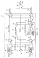
- FIGURE 3 shows a close-up block diagram of hit-less switching pointer aligner 14.
- working signal STS-1W is received and processed by working pointer follower 16
- protect signal STS-1P is received and processed by protect pointer follower 18.
- signals STS-1W and STS-1P are frame-aligned when received by pointer followers 16 and 18.
- Working signal STS-1W and protect signal STS-1P are also received unprocessed by 2:1 multiplexer 22.
- Working pointer follower 16 locates the STS-1 frame in working signal STS-1W and extracts working pointer value 26 and working payload 100.
- Protect pointer follower 18 locates the STS-1 frame in protect signal STS-1P and extracts protect pointer value 28 and protect payload 102.
- Working pointer follower 16 and protect pointer follower 18 discard the SONET frame (SONET overhead) after extracting working pointer value 26 and working payload 100 and protect pointer value 28 and protect payload 102.
- Working payload 100 and protect payload 102 are the actual user traffic.
- Working pointer follower 16 and protect pointer follower 18 forward working payload 100 and protect payload 102, respectively, to 2:1 multiplexer 24.
- Working pointer follower 16 and protect pointer follower 18 forward working pointer value 26 and protect pointer value 28 to comparator 20 and also to 2:1 multiplexer 32.
- Working pointer value 26 and protect pointer value 28 need to be aligned to ensure that the user traffic is not affected during a protection switch.
- Working pointer value 26 and protect pointer value 28 are received by comparator 20, which compares working pointer value 26 and protect pointer value 28 to determine, as between working signal STS-1W and protect signal STS-1P, which signal's payload is ahead (the signal having the ahead payload is the ahead signal, and the other is the behind signal). Because in this embodiment of the present invention working signal STS-1W and protect signal STS-1P are frame-aligned when they arrive at working and protect pointer followers 16 and 18, working pointer value 26 and protect pointer value 28 can be used to determine which of the two payloads (and hence which signal) is ahead and which one is behind.
- Comparator 20 determines which of working signal STS-1W or protect signal STS-1P is ahead and generates select bit 30, which it can then forward to 2:1 multiplexers 22, 24, 32, 50 and 52.
- Select bit 30 is a one-bit signal that can be low (a digital "0") if working signal STS-1W is ahead and high (a digital "1") if protect signal STS-1P is ahead.
- Select bit 30 can be received by 2:1 multiplexers 22, 24, 32, 50 and 52 and used by each to select which of the two signals coming into each multiplexer will be forwarded. For example, if select signal 30 is low, the signal coming into the low side of each 2:1 multiplexer will be forwarded. Conversely, if select signal 30 is high, the signal coming into the high side of each 2:1 multiplexer will be forwarded.
- 2:1 multiplexer 22 receives working signal STS-1W and protect signal STS-1P in an un-processed state. 2:1 multiplexer 22 also receives select bit 30 from comparator 20. Based on whether select bit 30 is high or low, 2:1 multiplexer 22 can select between working signal STS-1W and protect signal STS-1P. 2:1 multiplexer 22 selects whichever of the two signals received at the input side of 2:1 multiplexer 22 corresponds to the low or high state of select bit 30.
- select bit 30 can be low if working signal STS-1W is ahead and can be high if protect signal STS-1P is ahead.
- multiplexers 22, 24, 32, 50 and 52 will each receive a low value for select bit 30.
- Each of these multiplexers can then select, based on select bit 30, whichever of working signal STS-1W or protect signal STS-1P is being received on their corresponding low side.
- 2:1 multiplexer 22 for example, can, upon receiving a low select bit 30, select and forward protect signal STS-1P.
- 2:1 multiplexer 24 receives working payload 100 and protect payload 102 from working pointer follower 16 and protect pointer follower 18, respectively. 2:1 multiplexer 24 also receives select bit 30 from comparator 20. The operation of 2:1 multiplexer 24 is essentially the same as that of 2:1 multiplexer 22. In the case where working signal STS-1W is the ahead signal, select bit 30 can be low and 2:1 multiplexer 24 can select working payload 100 and forward it to delay buffer with control circuit 38 as ahead payload 36. Ahead payload 36 corresponds to the ahead signal payload. The behind signal, protect signal STS-1P in this example, is forwarded without processing by 2:1 multiplexer 22 as described above and sent through the circuit without modification as STS-1 bypass signal 34.
- 2:1 multiplexer 32 receives working pointer value 26 and protect pointer value 28 and also receives select bit 30.
- the operation of 2:1 multiplexer 32 is essentially the same as that of 2:1 multiplexers 22 and 24.
- 2:1 multiplexer 32 can select, based on select bit 30, either of working pointer value 26 or protect pointer value 28 which corresponds to the signal determined by comparator 20 to be the behind signal.
- 2:1 multiplexer 32 can then forward the behind signal's pointer value, protect pointer value 28 in this example, as bypass pointer value 46.
- Delay buffer with control circuit 38 receives ahead payload 36 and, in cooperation with pointer generator 42 and comparator 40, delays ahead payload 36 such that it is aligned with the payload of bypass signal 34. This is the actual payload alignment of working signals STS-1W and protect signal STS-1P.
- Delay buffer with control circuit 38 can be two-port RAM with independent read and write ports.
- FIGURE 4 shows a representative close-up block diagram detail of delay buffer with control circuit 38.
- Write counter 142 of control circuit 141 (control circuit 141 is shown within the dashed lines) is communicatively connected to the input side of delay buffer 140 and generates write addresses to write ahead payload 36 into delay buffer 140.
- Read counter 144 is communicatively connected to the output side of delay buffer 140 and generates read addresses for delay buffer 140 to read ahead payload 37 from delay buffer 140.
- Read counter 144 receives increment/decrement signal 44 from comparator 40 to insert the appropriate delay into ahead payload 36.
- Delay buffer 140 can be two-port Ram with independent read and write ports (at least one read port and one write port) controlled by read counter 144 and write counter 142.
- Phase detector 146 of FIGURE 4 is communicatively connected to write counter 142 and read counter 144, taking inputs from both. Phase detector 146 measures the offset between read counter 144 and write counter 142 and ensures that delay buffer 140 does not spill (i.e., that it does not run out of data or does not overflow with too much data). Phase detector 146 prevents delay buffer 140 from spilling by using the measured offset between read counter 144 and write counter 142 to generate a spill prevent signal 138. Phase detector 146 forwards spill prevent signal 138 to pointer generator 42. Pointer generator 42 uses spill prevent signal 138 to generate PG pointer value 48 such that delay buffer 140 does not spill while inserting the delay into ahead payload 36. The input side of delay buffer 140 is also communicatively connected to leak-out mechanism 148, which returns delay buffer 140 to its nominal position following an internal switch where the ahead signal becomes the behind signal and vice versa. Such a switch is more fully described below.
- delay buffer with control circuit 38 inserts a variable amount of delay into ahead payload signal 36.
- the amount of delay inserted by delay buffer with control circuit 38 is the amount of delay required to align working pointer value 26 and protect pointer value 28 (i.e., to align the payloads of working signal STS-1W and protect signal STS-1P) on the output side of the circuit.
- the amount of delay can be determined by bypass pointer value 46, which is forwarded by 2:1 multiplexer 32 to comparator 40.
- Bypass pointer value 46 is the same as the pointer value of bypass signal 34 (the behind signal), which in this example corresponds to protect signal STS-1P.
- hit-less switching pointer aligner 14 aligns the ahead signal pointer value with bypass pointer value 46.
- Pointer generator 42 receives ahead payload 37 from delay buffer with control circuit 38 and generates a third SONET overhead (frame) and PG pointer value 48.
- Pointer generator 42 can combine the third SONET overhead and PG pointer value 48 with ahead payload 37 to create a third digital signal 104 with a third payload identical to working payload 100 and protect payload 102.
- the third SONET overhead is aligned with the SONET overheads (frames) of working and protect signals STS-1W and STS-1P.
- Pointer generator 42 generates this SONET frame such that it is placed around ahead payload 37.
- PG pointer value 48 points to the location of ahead payload 37 within output signal 104.
- Pointer generator 42 wraps the STS frame around ahead payload 37 and inserts PG pointer value 48 into the outgoing data stream according to the location of ahead payload 37 relative to the STS frame.
- Pointer generator 42 forwards PG pointer value 48 to comparator 40 and forwards output signal 104 to 2:1 multiplexers 50 and 52.
- Comparator 40 receives and compares bypass pointer value 46 and PG pointer value 48 to determine the delay between them. Comparator 40 generates increment/decrement request signal 44 and forwards it to delay buffer with control circuit 38. Increment/decrement request signal 44 can be used to adjust the level of delay buffer with control circuit 38 to compensate for the delay between bypass pointer value 46 and PG pointer value 48 and bring them into alignment.
- Delay buffer with control circuit 38 can be a variable delay buffer.
- bypass pointer value 46 and PG pointer value 48 may not be equal. However, by action of comparator 40, delay buffer with control circuit 38, and pointer generator 42 operating a feedback loop, bypass pointer value 46 and PG pointer value 48 eventually can be brought into alignment. Working and protect payloads 100 and 102 will therefore likewise be aligned.
- Bypass pointer value 46 comes into comparator 40 with one value, and PG pointer value 48 is received by comparator 40 with a possibly different value (at least, initially).
- the value of PG pointer value 48 that pointer generator 42 initially generates for output signal 104 may not match the value of bypass pointer value 46. The payloads of output signal 104 and bypass signal 34 may therefore not be aligned.
- working payload 100 and protect payload 102 of working signal STS-1W and protect signal STS-1P may initially not be aligned. Over some short (on the order of milliseconds) period of time while comparator 40, delay buffer with control circuit 38 and pointer generator 42 are bringing bypass pointer value 46 and PG pointer value 48 into alignment, the payloads of bypass signal 34 and output signal 104 may not be aligned.
- Delay buffer with control circuit 38, pointer generator 42 and comparator 40 form a feedback loop that operates on bypass pointer value 46 and PG pointer value 48.
- This feedback loop operates by virtue of the SONET format pointers (i.e., bypass pointer value 46 and PG pointer value 48) having a mechanism by which the pointer values can change over time -- increment/decrement -- according to the SONET standard.
- the SONET standard provides for the pointer values changing by a maximum increment/decrement rate of one every four frames.
- the SONET format provides discretion as to which direction to move the pointer value, either up or down, at any given time, so long as payload integrity is maintained.
- Comparator 40 compares bypass pointer value 46 and PG pointer value 48 and determines there is a difference of five between them. Comparator 40 generates increment/decrement request signal 44 and forwards it to read counter 144 of delay buffer with control circuit 38 to insert the appropriate delay to align bypass pointer value 46 and PG pointer value 48.
- the value of the increment portion of increment/decrement request signal 44 would be high (a digital "1"), indicating an increment is required, and the decrement portion of increment/decrement request signal 44 would be low (a digital "0"), indicating no decrement is required.
- Delay buffer with control circuit 38 receives increment/decrement request signal 44 from comparator 40 and delays ahead payload 36 to add one increment to it.
- Pointer generator 42 receives newly-delayed working payload 37 and generates a new PG pointer value 48, whose value is now six.
- PG pointer value 48 is again forwarded to comparator 40 and is compared by comparator 40 to bypass pointer value 46, at which point a new increment/decrement request signal 44 is generated in the same manner described above. Every four frames, therefore, according to the SONET format, the value of PG pointer value 48 increases by one. The cycle repeats itself until bypass pointer value 46 and PG pointer value 48 are equal (i.e., they are aligned).
- comparator 40 When both bypass pointer value 46 and PG pointer value 48 are aligned, comparator 40 generates an increment/decrement request signal 44 wherein both the increment and the decrement signal portions are low, indicating no change is necessary. This process would occur in essentially the same manner in the situation where bypass pointer value 46 is initially less than PG pointer value 48, except that the decrement portion of increment/decrement request signal 44 in that case would be high and the increment portion signal would be low.
- bypass pointer value 46 it is also possible for bypass pointer value 46 to be incrementing/decrementing by one, according to the SONET format, over time (i.e., the behind signal payload location could be changing over time).
- the present invention can detect that bypass pointer value 46 has itself incremented/decremented and can correspondingly adjust PG pointer value 48 via delay buffer with control circuit 38, pointer generator 42, and comparator 40. The two signals can therefore be maintained in alignment. Note, however, that bypass pointer value 46 is itself not adjusted. Instead, PG pointer value 48 is adjusted to align the two pointer values.
- Bypass signal 34 and output signal 104 are both frame- and payload-aligned and can be forwarded to 2:1 multiplexers 50 and 52. 2:1 multiplexers 50 and 52 also receive select bit 30.
- 2:1 multiplexers 50 and 52 Operation of 2:1 multiplexers 50 and 52 is essentially the same as that of multiplexers 22, 24 and 32. Both select one or the other of bypass signal 34 and output signal 140 based on the state of select bit 30. If, as in the present description, working signal STS-1W is the ahead signal, select bit 30 is low. In response to a low select bit 30, 2:1 multiplexer 50 selects its low channel input, corresponding in this case to output signal 104, which corresponds to working signal STS-1 (the ahead signal). 2:1 multiplexer 52 likewise selects the signal received at its low input, which in this case corresponds to bypass signal 34. 2:1 multiplexers 50 and 52 forward their respective selected signal as output working signal STS-1W' 54 and output protect signal STS-1P' 56, respectively.
- 2:1 multiplexers 50 and 52 perform a bookkeeping function to place working signal STS-1W and protect signal STS-1P back on their original respective working and protect channels 7 and 9 after they have been payload aligned. Since both working and protect signals STS-1W and STS-1P (now bypass signal 34 and output signal 104, respectively) are both frame- and payload-aligned at the inputs to 2:1 multiplexers 50 and 52, it is not necessary to return each signal to its respective original channel. If desired, 2:1 multiplexers 50 and 52 can be employed, as in this embodiment of the present invention, to return the original working signal STS-1W and protect signal STS-1P to their original working and protect channels 7 and 9.
- 2:1 multiplexers 50 and 52 essentially undo the selection done at the beginning of the circuit (i.e., they place working signal STS-1W back on working channel 7 and protect signal STS-1P back on protect channel 9 in the event they were swapped around during processing in hit-less switching pointer aligner 14).
- hit-less switching pointer aligner 14 of this invention can be configured without 2:1 multiplexers 50 and 52.
- Bypass signal 34 and output signal 104 can instead be forwarded directly to a 2:1 multiplexer such as 2:1 multiplexer 58, where the hit-less protection switch can occur.
- 2:1 multiplexers 50 and 52 can forward output working signal STS-1W' 54 and output protect signal STS-1P' 56, respectively, to 2:1 multiplexer 58.
- 2:1 multiplexer 58 performs the selection (switching) between output working signal STS-1W' and output protect signals STS-1P'.
- 2:1 multiplexer 58 performs the actual hit-less switch between the original working and protect signals once they have been frame- and payload-aligned. 2:1 multiplexer 58 forwards hit-lessly selected STS-1' signal 5 to the rest of the system.
- hit-less switching pointer aligner 14 of the present invention could be processing working signal STS-1W as the ahead signal through elastic buffer 38 and pointer generator 42, and could then have to switch to instead send protect signal STS-1P through the delay portion of the circuit if working signal STS-1W becomes the behind signal.
- Hit-less switching pointer aligner 14 of the present invention is designed to also accomplish in a hit-less manner this type of crossing over from one signal initially being ahead to being behind.
- the present invention accomplishes this hit-less exchange by ensuring that the internal switch from sending one signal to the delay portion of the circuit to sending the other signal to the delay portion of the circuit occurs during the SONET transport overhead portion of the signal and not at the payload pointer byte location of the signal.
- By performing the cross-over at the right time (during the SONET transport overhead) working and protect payloads 100 and 102 will not be affected by any glitches that may occur as a result of the switch because the payload will not be at the location being pointed to at the time of the switch. Therefore, the cross-over from one signal being the ahead signal to the other signal being the ahead signal can be made transparent to the payload.
- leak-out mechanism 148 of FIGURE 4 returns delay buffer 140 to its nominal position, making it ready to begin delaying the new ahead signal.
- comparator 20 would have compared working pointer value 26 and protect pointer value 28 and determined that working signal STS-1W (having pointer value 4) is ahead of protect signal STS-1P (having pointer value 6) by two increments.
- hit-less switching pointer aligner 14 of the present invention would select working signal STS-1W for processing through delay buffer with control circuit 38 to insert a delay of two increments.
- working payload 100 would be reconstructed with a pointer value of 6, as previously discussed, thereby matching the pointer value of protect signal STS-1P.
- incoming protect pointer value 28 abruptly changes its pointer value from six to three.
- comparator 20 would decide that protect signal STS-1P is now ahead of working signal STS-1W and would re-route protect signal STS-1P's protect payload 102 through delay buffer with control circuit 38. If this action were to be carried out immediately, working signal STS-1W would be bypassed through 2:1 multiplexer 22 as STS-1 bypass signal 34. To equipment downstream of hit-less switching pointer aligner 14, this action would appear as if working pointer value 28 had abruptly changed from six (the delayed output value) to four (the unprocessed input value) in the course of a single frame, a traffic-affecting action for SONET pointers.
- the re-routing of protect signal STS-1P to delay buffer with control circuit 38 can be delayed until working signal STS-1W has an opportunity to be leaked back to its nominal (input) pointer value via legal SONET pointer actions. Once working signal STS-1W has been leaked back to its nominal position, it can be safely re-routed to the bypass path and protect signal STS-1P can be safety re-routed through delay buffer with control circuit 38.
- output protect pointer value 28 jumps from six to three at the output of hit-less switching pointer aligner 14 due to the action of the incoming protect pointer value 28 (the protect traffic is being bypassed because it is now seen as being ahead of the working traffic).
- hit-less switching pointer aligner 14 of the present invention determines that working signal STS-1W has become the behind signal and begins to decrement working pointer value 26 (indicated above by the letter D), as described above as part of the description of FIGURE 3.
- the outbound value of working pointer value 26 is the same as the inbound value of working pointer value 26, and the working traffic can be safely bypassed.
- hit-less switching pointer aligner 14 re-routes protect signal STS-1P into delay buffer with control circuit 38 with an initial delay of one increment. This allows hit-less switching pointer aligner 14 to increment the outbound protect pointer value 28 (indicated above by the letter I) so that it matches the outbound value of working pointer value 26.
- the present invention regenerates only a single SONET frame using a single pointer processor 42.
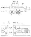
- the prior art hit-less switching system 600 shown in FIGURE 1 includes working and protect signals STS-1W and STS-1P transmitted along working and protect channels 7 and 9, respectively.
- Working and protect signals STS-1W and STS-1P are received by delay buffers 2, which are communicatively connected to corresponding pointer processors 4.
- Delay buffers 2 are used to frame-align working and protect signals STS-1W and STS-1P.
- Pointer processors 4 are themselves communicatively connected to one another. Pointer processors 4 payload-align working and protect signals STS-1W and STS-1P and regenerate a separate SONET frame for each of their payloads.
- the improved hit-less switching system of the present invention unlike the prior art of FIGURE 1, eliminates the need for regenerating a second SONET frame, and therefore only a single pointer processor function will be required to accomplish payload alignment.
- hit-less pointer aligner 14 of the present invention aligns the payloads of incoming working signal STS-1W and protect signal STS-1P in the case where both signals are already frame-aligned when they arrive at hit-less pointer aligner 14. In such a case, frame location within each signal relative to the other signal is not an issue.
- Frame location within the signal can be limited by delay buffer 140 depth (i.e., by how much offset is built into elastic buffer 140).
- delay buffer 140 depth By adjusting delay buffer 140 depth, the amount of frame offset between working channel 7 and protect channel 9 can be correspondingly adjusted. If the degree of offset in frame location between working and protect signals STS-1W and STS-1P is not within delay buffer 140 depth, spilling of delay buffer 140 can result.
- a deep delay buffer 140 can buffer many frames, but if delay buffer 140 is only one frame deep, then working and protect signals STS-1W and STS-1P can only be offset by about one frame.
- Delay buffer 140 can be of whatever size necessary; for example, 16 bytes deep.
- the size of delay buffer 140 determines how much variation can be absorbed between working pointer value 26 and protect pointer value 28.
- Delay buffer 140 RAM should be sized to ensure that, based on the path difference, working pointer value 26 and protect pointer value 28 are within one delay buffer 140 depth of each other.
- the minimum delay buffer 140 size should be approximately equal to the amount of delay to be compensated plus some fixed overhead for frequency justification, overhead gaps in the payload, and a guard band.
- Delay buffer 140 should be sized according to the maximum anticipated offset between working and protect payloads 100 and 102.
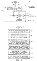
- FIGURE 5 is a flow chart diagramming the overall operation of hit-less switching pointer aligner 14 of the present invention.
- Step 300 corresponds to working and protect signals STS-1W and STS-1P inputting into hit-less switching pointer aligner 14 of FIGURE 3.
- working and protect pointer followers 16 and 18 extract working pointer value 26 and protect pointer value 28 from working signal STS-1W and protect signal STS-1P, respectively.
- Working and protect pointer followers 16 and 18 also remove the SONET overhead from working and protect signals STS-1W and STS-1P and forward working payload 100 and protect payload 102 to 2:1 multiplexer 24.
- Working pointer value 26 and protect pointer value 28 are forwarded to comparator 20 by working and protect pointer followers 16 and 18.
- comparator 20 determines which STS-1 payload is ahead and which STS-1 payload is behind. Comparator 20 does this by comparing working pointer value 26 and protect pointer value 28 and generating select bit 30, which can be low when the working signal is ahead or high when the protect signal is ahead. Comparator 20 forwards select bit 30 to 2:1 multiplexers 22, 24, 32, and, optionally, to 2:1 multiplexers 50 and 52.
- Step 306 corresponds to 2:1 multiplexers 22, 24 and 32 operating together to route the ahead signal payload to delay buffer with control circuit 38, the behind signal pointer value to comparator 40, and the behind signal to the bypass portion of the circuit.
- comparator 40 compares bypass pointer value 46 and PG pointer value 48 and generates increment/decrement request signal 44 for delay buffer with control circuit 38 to operate on ahead payload 36 to align it with bypass signal 34.
- Comparator 40, delay buffer with control circuit 38, and pointer generator 42 operate together to form a feedback loop wherein PG pointer value 48 is acted on to alter its value to match bypass pointer value 46 over a series of increment/decrement request signals from comparator 40.
- bypass signal 34 and output signal 104 are both frame- and payload-aligned.
- bypass signal 34 and output signal 104 are both payload-aligned at this point and can be frame-aligned downstream of hit-less switching pointer aligner 14.
- a hit-less selection can now be performed between working channel 7 and protect channel 9.
- Output signal 104 and bypass signal 34 are now frame- and payload-aligned and can be returned to their respective channels by operation of 2:1 multiplexers 50 and 52 and forwarded to 2:1 multiplexer 58.
- 2:1 multiplexer 58 performs the actual hit-less selection between working and protect channels 7 and 9.
- working and protect signals STS-1W and STS-1P have been described in terms of a single frame which is operated on by hit-less switching pointer aligner 14; however, each can be comprised of a series of frames and corresponding series of payloads and payload pointers transported on a given channel. Likewise, the frames (overheads) of a given signal can have starting locations on the working channel different from those on the protect channel for a given payload.
- the present invention provides an improved system and method of processing digital signals in a telecommunications system that allows for hit-less switching between a first digital signal in which a first payload, a first pointer value, and a first frame are transported on a first channel, and a second digital signal in which a second payload identical to the first payload, a second pointer value, and a second frame are transported on a second channel.
Landscapes
- Engineering & Computer Science (AREA)
- Computer Networks & Wireless Communication (AREA)
- Signal Processing (AREA)
- Physics & Mathematics (AREA)
- Electromagnetism (AREA)
- Computer Hardware Design (AREA)
- Time-Division Multiplex Systems (AREA)
Applications Claiming Priority (2)
| Application Number | Priority Date | Filing Date | Title |
|---|---|---|---|
| US09/354,865 US6515962B1 (en) | 1999-07-16 | 1999-07-16 | Hit-less switching pointer aligner apparatus and method |
| US354865 | 1999-07-16 |
Publications (2)
| Publication Number | Publication Date |
|---|---|
| EP1069698A2 true EP1069698A2 (fr) | 2001-01-17 |
| EP1069698A3 EP1069698A3 (fr) | 2002-10-23 |
Family
ID=23395240
Family Applications (1)
| Application Number | Title | Priority Date | Filing Date |
|---|---|---|---|
| EP99121941A Withdrawn EP1069698A3 (fr) | 1999-07-16 | 1999-11-08 | Apparail et procédé d'aligner un pointeur pour commutation sans parasite |
Country Status (3)
| Country | Link |
|---|---|
| US (1) | US6515962B1 (fr) |
| EP (1) | EP1069698A3 (fr) |
| CA (1) | CA2288578A1 (fr) |
Cited By (2)
| Publication number | Priority date | Publication date | Assignee | Title |
|---|---|---|---|---|
| RU2290759C2 (ru) * | 2002-09-18 | 2006-12-27 | Нек Корпорейшн | Устройство радиосвязи и система радиосвязи, предназначенная для использования с устройством |
| WO2008086418A3 (fr) * | 2007-01-09 | 2008-08-28 | Sr Telecom Inc | Station de base sans fil de réserve |
Families Citing this family (8)
| Publication number | Priority date | Publication date | Assignee | Title |
|---|---|---|---|---|
| US7167442B2 (en) * | 2001-05-22 | 2007-01-23 | Nortel Networks Limited | Hitless protection switching |
| US7002909B2 (en) * | 2001-07-25 | 2006-02-21 | Dorsal Networks, Inc. | Zero data loss network protection |
| US6766482B1 (en) | 2001-10-31 | 2004-07-20 | Extreme Networks | Ethernet automatic protection switching |
| US7161963B2 (en) * | 2002-03-25 | 2007-01-09 | Intel Corporation | Frame multiplexer |
| US7870444B2 (en) * | 2005-10-13 | 2011-01-11 | Avago Technologies Fiber Ip (Singapore) Pte. Ltd. | System and method for measuring and correcting data lane skews |
| US7656791B1 (en) | 2006-07-19 | 2010-02-02 | Pmc-Sierra, Inc. | Systems and methods for hitless equipment protection |
| US8001409B2 (en) * | 2007-05-18 | 2011-08-16 | Globalfoundries Inc. | Synchronization device and methods thereof |
| JP7299530B2 (ja) * | 2019-08-05 | 2023-06-28 | 日本電信電話株式会社 | 伝送装置及び伝送方法 |
Family Cites Families (16)
| Publication number | Priority date | Publication date | Assignee | Title |
|---|---|---|---|---|
| US5051979A (en) | 1990-06-28 | 1991-09-24 | At&T Bell Laboratories | Method and apparatus for errorless switching |
| JPH0498917A (ja) | 1990-08-17 | 1992-03-31 | Hitachi Ltd | Atm伝送路の無瞬断切替方法及び回路 |
| US5271001A (en) | 1990-10-31 | 1993-12-14 | Nec Corporation | Synchronous terminal station system |
| US5285441A (en) | 1992-03-17 | 1994-02-08 | At&T Bell Laboratories | Errorless line protection switching in asynchronous transer mode (ATM) communications systems |
| GB9403223D0 (en) * | 1994-02-19 | 1994-04-13 | Plessey Telecomm | Telecommunications network including remote channel switching protection apparatus |
| DE69532939T2 (de) * | 1994-07-18 | 2005-06-16 | Nippon Telegraph And Telephone Corp. | Eine störungsfreie Wegumschaltungsanordnung und Verfahren |
| US5745476A (en) | 1996-07-16 | 1998-04-28 | At&T Corp. | Errorless switching techniques in ring network |
| US5987027A (en) | 1996-11-08 | 1999-11-16 | Alcatel | Cross-connect multirate/multicast SDH/SONET rearrangement procedure and cross-connect using same |
| JPH10262017A (ja) * | 1997-03-19 | 1998-09-29 | Fujitsu Ltd | Sdh多重伝送システム及びその装置 |
| US6078596A (en) * | 1997-06-26 | 2000-06-20 | Mci Communications Corporation | Method and system of SONET line trace |
| DE19734425A1 (de) | 1997-08-08 | 1999-02-11 | Schurr Stahlecker & Grill | Spurlager für einen Schaft eines OE-Spinnrotors |
| US6075631A (en) * | 1997-09-05 | 2000-06-13 | Bell Communications Research, Inc. | Hitless reconfiguration of a wavelength division multiplexed optical communication network |
| US6034688A (en) | 1997-09-15 | 2000-03-07 | Sony Corporation | Scrolling navigational display system |
| WO1999016010A1 (fr) | 1997-09-22 | 1999-04-01 | Intelligent Reasoning Systems, Inc. | Systeme et procede d'inspection visuelle automatisee servant a detecter et a classer des defauts |
| US6246668B1 (en) * | 1998-06-09 | 2001-06-12 | Nortel Networks Limited | Hitless manual path switching using linked pointer processors |
| US6195330B1 (en) * | 1998-11-05 | 2001-02-27 | David C. Sawey | Method and system for hit-less switching |
-
1999
- 1999-07-16 US US09/354,865 patent/US6515962B1/en not_active Expired - Fee Related
- 1999-11-04 CA CA002288578A patent/CA2288578A1/fr not_active Abandoned
- 1999-11-08 EP EP99121941A patent/EP1069698A3/fr not_active Withdrawn
Cited By (2)
| Publication number | Priority date | Publication date | Assignee | Title |
|---|---|---|---|---|
| RU2290759C2 (ru) * | 2002-09-18 | 2006-12-27 | Нек Корпорейшн | Устройство радиосвязи и система радиосвязи, предназначенная для использования с устройством |
| WO2008086418A3 (fr) * | 2007-01-09 | 2008-08-28 | Sr Telecom Inc | Station de base sans fil de réserve |
Also Published As
| Publication number | Publication date |
|---|---|
| US6515962B1 (en) | 2003-02-04 |
| EP1069698A3 (fr) | 2002-10-23 |
| CA2288578A1 (fr) | 2001-01-16 |
Similar Documents
| Publication | Publication Date | Title |
|---|---|---|
| US6195330B1 (en) | Method and system for hit-less switching | |
| EP0463808B1 (fr) | Commutation d'un signal numérique sur un canal alternatif transmis par une voie différente | |
| US6246668B1 (en) | Hitless manual path switching using linked pointer processors | |
| US8335240B2 (en) | Methods and apparatus for aligning a communications frame to a predetermined phase | |
| US7839772B2 (en) | Line redundant device and method | |
| JPH01501589A (ja) | スイッチングシステム | |
| US6515962B1 (en) | Hit-less switching pointer aligner apparatus and method | |
| US6717960B1 (en) | Method for reconstructing an aggregate ATM cell stream and related device | |
| US6963560B2 (en) | Method and system for frame and pointer alignment of SONET data channels | |
| JPH05252150A (ja) | Sdhデータ伝送タイミング | |
| US7197031B2 (en) | Cross-connection of high bandwidth signal traffic across independent parallel shelves | |
| JPH0317422B2 (fr) | ||
| EP1158711A2 (fr) | Concaténer virtuellement à travers de processeurs indépendants de pointeurs | |
| US5825821A (en) | Hitless switch device and method of switching between different paths | |
| US6144642A (en) | Signal transfer device in a telecommunications network | |
| JP4610498B2 (ja) | 伝送装置、伝送方法、及びプログラム | |
| US7161963B2 (en) | Frame multiplexer | |
| JP3202286B2 (ja) | Sdh光伝送方式における伝送路切替方式 | |
| JP2868398B2 (ja) | 伝送路切替装置 | |
| JPH01263566A (ja) | 伝送遅延差測定方式 | |
| US6987759B1 (en) | Method for using a pre-configured TDM switch and traffic discard to facilitate UPSR selection | |
| EP1198086A2 (fr) | Procédé et dispositif de gestion d'alignement de pointeurs dans de réseaux de télécommunication | |
| JPH0243842A (ja) | 通信情報の信号情報への併用方式 | |
| JPH08204670A (ja) | パス切替時の系合わせ方式 | |
| JPH06132944A (ja) | 伝送路無瞬断切替方法 |
Legal Events
| Date | Code | Title | Description |
|---|---|---|---|
| PUAI | Public reference made under article 153(3) epc to a published international application that has entered the european phase |
Free format text: ORIGINAL CODE: 0009012 |
|
| AK | Designated contracting states |
Kind code of ref document: A2 Designated state(s): AT BE CH CY DE DK ES FI FR GB GR IE IT LI LU MC NL PT SE |
|
| AX | Request for extension of the european patent |
Free format text: AL;LT;LV;MK;RO;SI |
|
| PUAL | Search report despatched |
Free format text: ORIGINAL CODE: 0009013 |
|
| AK | Designated contracting states |
Kind code of ref document: A3 Designated state(s): AT BE CH CY DE DK ES FI FR GB GR IE IT LI LU MC NL PT SE |
|
| AX | Request for extension of the european patent |
Free format text: AL;LT;LV;MK;RO;SI |
|
| 17P | Request for examination filed |
Effective date: 20030416 |
|
| AKX | Designation fees paid |
Designated state(s): AT BE CH CY DE DK ES FI FR GB GR IE IT LI LU MC NL PT SE |
|
| 17Q | First examination report despatched |
Effective date: 20030728 |
|
| GRAP | Despatch of communication of intention to grant a patent |
Free format text: ORIGINAL CODE: EPIDOSNIGR1 |
|
| STAA | Information on the status of an ep patent application or granted ep patent |
Free format text: STATUS: THE APPLICATION IS DEEMED TO BE WITHDRAWN |
|
| 18D | Application deemed to be withdrawn |
Effective date: 20040928 |