EP1069666A1 - Controle de puissance active dans un système de transmission à courant continu à hute tension - Google Patents
Controle de puissance active dans un système de transmission à courant continu à hute tension Download PDFInfo
- Publication number
- EP1069666A1 EP1069666A1 EP99112542A EP99112542A EP1069666A1 EP 1069666 A1 EP1069666 A1 EP 1069666A1 EP 99112542 A EP99112542 A EP 99112542A EP 99112542 A EP99112542 A EP 99112542A EP 1069666 A1 EP1069666 A1 EP 1069666A1
- Authority
- EP
- European Patent Office
- Prior art keywords
- converter station
- voltage
- active power
- reference value
- voltage reference
- Prior art date
- Legal status (The legal status is an assumption and is not a legal conclusion. Google has not performed a legal analysis and makes no representation as to the accuracy of the status listed.)
- Granted
Links
Images
Classifications
-
- H—ELECTRICITY
- H02—GENERATION; CONVERSION OR DISTRIBUTION OF ELECTRIC POWER
- H02J—ELECTRIC POWER NETWORKS; CIRCUIT ARRANGEMENTS OR SYSTEMS FOR SUPPLYING OR DISTRIBUTING ELECTRIC POWER; SYSTEMS FOR STORING ELECTRIC ENERGY
- H02J3/00—Circuit arrangements for AC mains or AC distribution networks
- H02J3/36—Arrangements for transfer of electric power between AC networks via high-voltage DC [HVDC] links; Arrangements for transfer of electric power between generators and networks via HVDC links
-
- H—ELECTRICITY
- H02—GENERATION; CONVERSION OR DISTRIBUTION OF ELECTRIC POWER
- H02M—APPARATUS FOR CONVERSION BETWEEN AC AND AC, BETWEEN AC AND DC, OR BETWEEN DC AND DC, AND FOR USE WITH MAINS OR SIMILAR POWER SUPPLY SYSTEMS; CONVERSION OF DC OR AC INPUT POWER INTO SURGE OUTPUT POWER; CONTROL OR REGULATION THEREOF
- H02M7/00—Conversion of AC power input into DC power output; Conversion of DC power input into AC power output
- H02M7/66—Conversion of AC power input into DC power output; Conversion of DC power input into AC power output with possibility of reversal
- H02M7/68—Conversion of AC power input into DC power output; Conversion of DC power input into AC power output with possibility of reversal by static converters
- H02M7/72—Conversion of AC power input into DC power output; Conversion of DC power input into AC power output with possibility of reversal by static converters using discharge tubes with control electrode or semiconductor devices with control electrode
- H02M7/75—Conversion of AC power input into DC power output; Conversion of DC power input into AC power output with possibility of reversal by static converters using discharge tubes with control electrode or semiconductor devices with control electrode using devices of a thyratron or thyristor type requiring extinguishing means
- H02M7/757—Conversion of AC power input into DC power output; Conversion of DC power input into AC power output with possibility of reversal by static converters using discharge tubes with control electrode or semiconductor devices with control electrode using devices of a thyratron or thyristor type requiring extinguishing means using semiconductor devices only
- H02M7/7575—Conversion of AC power input into DC power output; Conversion of DC power input into AC power output with possibility of reversal by static converters using discharge tubes with control electrode or semiconductor devices with control electrode using devices of a thyratron or thyristor type requiring extinguishing means using semiconductor devices only for high voltage direct transmission link
-
- Y—GENERAL TAGGING OF NEW TECHNOLOGICAL DEVELOPMENTS; GENERAL TAGGING OF CROSS-SECTIONAL TECHNOLOGIES SPANNING OVER SEVERAL SECTIONS OF THE IPC; TECHNICAL SUBJECTS COVERED BY FORMER USPC CROSS-REFERENCE ART COLLECTIONS [XRACs] AND DIGESTS
- Y02—TECHNOLOGIES OR APPLICATIONS FOR MITIGATION OR ADAPTATION AGAINST CLIMATE CHANGE
- Y02E—REDUCTION OF GREENHOUSE GAS [GHG] EMISSIONS, RELATED TO ENERGY GENERATION, TRANSMISSION OR DISTRIBUTION
- Y02E60/00—Enabling technologies; Technologies with a potential or indirect contribution to GHG emissions mitigation
- Y02E60/60—Arrangements for transfer of electric power between AC networks or generators via a high voltage DC link [HVCD]
Definitions
- the invention relates to a method for controlling active power flow in a high voltage direct current transmission system having a first and a second converter station coupled to each other via a direct current link, each converter station with a voltage source converter, wherein the first converter station controls the voltage of the direct current link, at the first converter station, in dependence on a first voltage reference value, and the second converter station controls the active power flow through the second converter station, and to a high voltage direct current transmission system for carrying out the method.
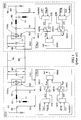
- FIG. 1 shows in the form of a schematic single line and block diagram a high voltage direct current transmission system as known in the prior art.
- a first and a second converter station STN1 and STN2 respectively are coupled to each other via a direct current (dc) link having two pole conductors W1 and W2 respectively.
- the pole conductors are typically cables but may also at least to a part be in the form of overhead lines.
- Each converter station has a capacitor equipment, in this embodiment schematically shown as capacitors C1 and C2 respectively, coupled between the pole conductors, and comprises a voltage source converter, CON1 and CON2 respectively.
- Each converter comprises two three-phase groups of semiconductor valves in six-pulse bridge connection.
- the semiconductor valves comprises, in a way known per se, branches of gate turn on/turn off semiconductor elements, for example power transistors of so-called IGBT-type, and diodes in anti-parallel connection with these elements.
- Each converter is via phase inductors, PI1 and PI2 respectively, coupled to a respective three-phase alternating current (ac) electric power network, N1 and N2.
- ac alternating current
- the converters may be coupled to the three-phase networks via transformers, in which case the phase inductors in some cases may be omitted.
- Filter equipment F1 and F2 respectively is coupled in shunt connection at connection points between the phase inductors and the three-phase networks.
- the ac-voltage of the alternating current network N1 at the connection point of the filter F1 is designated UL1 and is sensed with a sensing device M1.
- the ac-current at the converter CON1 is designated Iv1 and is sensed with a measuring device M2.
- the ac-voltage at the connection point of the filter F2 is designated UL2 and is sensed with a sensing device M3
- the ac-current at the converter CON2 is designated Iv2 and is sensed with a measuring device M4.
- the dc-voltage across the capacitor equipment C1 is designated Udc1 and is sensed with an only symbolically shown sensing device M5
- the dc-voltage across the capacitor equipment C2 is designated Udc2 and is sensed with an only symbolically shown sensing device M6.
- the first converter station comprises control equipment CTRL1 and the second converter station control equipment CTRL2 of similar kind.
- the control equipments operate in a conventional way with three phase units (voltages and currents) converted to and expressed in a two-phase ⁇ -reference frame as well as in a rotating two-phase dq - reference frame.
- the phases of the three-phase alternating current electric power networks are referred to as the abc -reference frame.
- Vector units are in the following illustrated with a dash on top ( x ).
- the reference frame is, where appropriate, indicated in an upper index (for example x dq ).
- Control equipment CTRL1 comprises a dc-voltage controller UdcREG, an ac-voltage controller UacREG, selector means SW1 and SW2 respectively, and an internal converter current control IREG.
- the dc-voltage controller is supplied with the sensed dc-voltage Udc1 and a first voltage reference value Udc1R thereof, and forms in dependence of the deviation of the actual value Udc1 and the first voltage reference value Udc1R an output signal P1C.
- the ac-voltage controller is supplied with the sensed ac-voltage UL1 and a voltage reference value UL1R thereof, and forms in dependence of the deviation of the actual value UL1 and the reference value UL1R an output signal Q1C.
- Each of the dc-voltage controller and ac-voltage controller comprises a (not shown) difference forming member, forming the deviation between respective reference values and actual values, which deviation is supplied to and processed in a (not shown) controller member having for example a proportional/integrating characteristic.
- the voltage controllers thus provide feedback control of the respective voltages.
- the output signal P1C and a reference value P1R for the active power flow through the converter CON1 are supplied to two different inputs on the selector means SW1, and the output signal Q1C and a reference value Q1R for the reactive power flow through the converter CON1 are supplied to two different inputs on the selector means SW2.
- the reference values P1R and Q1R may be set manually, in particular the reference value P1R may also be the output of another controller such as a frequency controller.
- either of the output signal P1C and the reference value P1R is transferred and supplied to the internal converter current control IREG in the form of a signal designated p ref 1 , having the significance of an active power order.
- either of the output signal Q1C and the reference value Q1R is transferred and supplied to the internal converter current control IREG in the form of a signal designated q ref 1 , having the significance of a reactive power order.
- each converter station can operate in four different modes, one of dc-voltage control and active power control and one of ac-voltage control and reactive power control.
- one of the converter stations for example the first one, operates under dc-voltage control
- the second converter station (as well as other, not shown, converter stations, which may be coupled to the first converter station via other direct current links) operates under active power control and under ac-voltage or reactive power control.
- the operation modes are set either manually by an operator, or, under certain conditions, automatically by a not shown sequential control system.
- the internal converter current control IREG is of a kind known per se and comprises a current-order calculating unit and a converter control unit (not shown).
- the current-order calculating unit comprises a current-order calculating member and a current limiting member.
- the above mentioned active and reactive power order signals, p ref 1 and q ref 1 respectively, are supplied to the current-order calculating unit.
- current reference values expressed in the dq-reference frame as i d / ref and i q / ref respective, are calculated in dependence on the power orders.
- the current reference values i d / ref and i q / ref are supplied to the current limiting member and therein limited, as the case may be, in accordance with specified operating conditions for the transmission system.
- the current limiting member outputs the so limited values as a current vector i ' dq / ref to the converter control unit.
- the converter control unit has an inner ac-current control feed back loop which, in dependence on the supplied current vector i ' dq / ref and a phase reference signal, generates a voltage reference vector.
- This voltage reference vector is supplied to a pulse-generating member that in dependence thereon generates a train Fp1 of turn on/turn off orders supplied to the semiconductor valves according to a predetermined pulse width modulation pattern.
- the phase reference signal is in a conventional manner generated by a phase locked loop and at least under steady state conditions locked to the phase of the filter bus voltage of the alternating current electric power network.
- Control equipment CTRL2 in the second converter station is similar to control equipment CTRL1 described above, only, in figure 1, index 1 for the various signals is at appropriate occasions changed to index 2.
- one of the converter stations operates under dc-voltage control, controlling the dc-voltage of the dc-link at that converter station, whereas the second converter station operates under active power control and under ac-voltage or reactive power control.
- the converter station operating under dc-voltage control then has an active power slack function, providing the active power requested by the second converter station and maintaining the dc-voltage at the desired value.
- certain disturbances in the power networks and in the transmission system in particular transient disturbances in the alternating current electric power network to which the dc-voltage controlling converter station is coupled, for example phase to ground faults, may result in considerable dc-voltage variations on the direct current link.
- the first converter station may not be able to balance the active power required by the second converter station.
- Such variations may reach such a magnitude that they would lead to a shut down of the dc transmission system, such as a temporary blocking of the converter station by an over current protection or by an over- or under voltage protection, if no measures were taken.
- One such measure is to temporarily change the operating mode of the second converter station to dc-voltage control mode in order to keep the dc-transmission system in operation.
- the operating mode of the second converter should then again be changed to active power control mode in order to recover the active power flow to the pre-fault level.
- Such mode changes to dc-voltage control mode have to be done very fast in order to avoid dc over voltages on the dc-link. Furthermore, to determine the time at which a change back to active power control mode may be accomplished requires in practice intervention of the operator of the dc transmission system and communication between the converter stations.
- the object of the invention is to provide a method of the kind described in the introduction, which eliminates the above mentioned disadvantages related to change of operating modes as known in the prior art, and a high voltage direct current transmission system for carrying out the method.
- this object is accomplished by having both the first and the second converter stations operating in dc voltage control mode, the first converter station having means for control of the voltage of the direct current link in dependence on a first voltage reference value and the second converter station having means for control of the active power flow through the second converter station, which means comprises voltage control means for control of the direct voltage of the second converter station in dependence on a second voltage reference value, said second voltage reference value being formed in dependence on a third voltage reference value and on a voltage reference correction signal formed in dependence on a quantity indicative of the active power flow through the second converter station and a reference value thereof.
- the means for control of the active power flow through the second converter station comprises controller means for forming said voltage reference correction signal, having as inputs said quantity indicative of the active power flow through the second converter station and said reference signal thereof, and summing means for forming said second voltage reference value as a sum of said voltage reference correction signal and said third voltage reference value.
- said quantity indicative of the active power flow through the second converter station is the active power flow through the second converter station, calculated from measurements of voltages and currents in the alternating current network to which the second converter station is coupled.
- the dc-voltage variations in the transmission system during a disturbance will be reduced and the power recovery process after a disturbance will be simplified and faster.
- the need for a communication system between the converter stations may be eliminated, such systems being quite complicated especially in multi-terminal systems.
- the following description relates both to the method and to the high voltage direct current transmission system, and the block diagrams can thus be regarded both as signal flow diagrams and block diagrams of control equipment for the transmission system.
- the functions to be performed by the blocks shown in the block diagrams may in applicable parts be implemented by means of analogue and/or digital technique in hard-wired circuits, or as programs in a microprocessor.
- the in the figures shown blocks are mentioned as members, filters, devices etc. they are, in particular where their functions are implemented as software for a microprocessor, to be interpreted as means for accomplishing the desired function.
- the expression "signal" can also be interpreted as a value generated by a computer program and appearing only as such. Only functional descriptions of the blocks are given below as these functions can be implemented in manners known per se by persons skilled in the art.
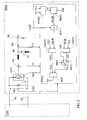
- Figure 2 shows in the form of a schematic single line and block diagram a high voltage direct current transmission system of similar kind as the one described with reference to figure 1, but with control equipment of the second converter station in accordance with the invention.
- the second converter station is in figure 2 designated as STN2', and its control equipment as CTRL2', otherwise same designation numbers refer to parts of similar kind in both figures.
- STN2' the control equipment of the converter station STN1
- CTRL2' control equipment
- Control equipment CTRL2' comprises an internal converter current control IREG as described in connection with figure 1.
- the internal converter current control receives as inputs a signal designated p ref2 , having the significance of an active power order and being the output of the dc-voltage controller UdcREG, and a signal designated q ref2 , having the significance of a reactive power order.
- the signal q ref2 is one of the output Q2C of the ac-voltage controller UacREG and a reference value Q2R for the reactive power flow through the converter CON2.
- the values Q2C and Q2R are selectable via the selector means SW2 in dependence on a second mode signal MD22.
- the dc-voltage of the second converter station is controlled in dependence on a second voltage reference value Udc2R.
- the second voltage reference value is formed in dependence on a third voltage reference value Udc2R' and on a voltage reference correction signal ⁇ UdcR, the forming of which will be explained below.
- An active power controller PREG has as inputs a quantity P2 indicative of the actual value of the active power flow through the second converter station and a reference value P2R thereof, and outputs in dependence of a deviation between these inputs the voltage reference correction signal ⁇ UdcR.
- the voltage reference correction signal and the third voltage reference value Udc2R' are supplied to a summing means SUM, which forms the second voltage reference value Udc2R as the sum of its inputs.
- the active power controller comprises in a conventional way a (not shown) difference forming member, forming the deviation between the reference value and the actual value, which deviation is supplied to and processed in a (not shown) controller member, having for example a proportional/integrating characteristic, thus providing feed-back control of the active power flow through the second converter station.
- the active power controller forms a voltage reference correction signal thereby adjusting the dc-voltage of the second converter station to a value that results in the desired active power flow through the converter.
- the voltage at the second converter station will be maintained by the voltage control of the second converter station.
- the first converter station again establishes the voltage control of the direct current link at the first converter station.
- the second converter station will then automatically return to active power control to reach the active power operating point that existed before the disturbance.
- the quantity P2 indicative of the actual value of the active power flow through the second converter station is calculated in a calculating member PCALC in dependence on sensed values of the filter bus voltage UL2 and the ac-current Iv2 flowing through the converter.
- the voltage reference correction signal ⁇ UdcR is set equal to the first voltage reference value Udc1R of the first converter station. This means that the voltage reference correction signal ⁇ UdcR at least theoretically will be zero when the active power reference value P2R is set to zero, and that its absolute value will reach its maximum when the active power reference value is set at a maximum value. Consequently, with knowledge of the resistance of the direct current link, the limitation values of the output of the active power controller can easily be defined.
- the quantity indicative of the actual value of the active power flow through the second converter station may also be the actual frequency f 2 as sensed in the network N2, and the reference value thereof be a frequency reference value f 2 R .
- the invention is described in connection with a two-terminal system, it is also applicable to multi-terminal transmission systems, where more than one converter station is coupled to the voltage controlling converter station and operates in an active power control mode, as well as to back-to-back systems.
- the actual value of the active power may of course also be obtained in other per se known ways.
Landscapes
- Engineering & Computer Science (AREA)
- Power Engineering (AREA)
- Supply And Distribution Of Alternating Current (AREA)
- Inverter Devices (AREA)
Priority Applications (6)
| Application Number | Priority Date | Filing Date | Title |
|---|---|---|---|
| EP99112542A EP1069666B1 (fr) | 1999-07-01 | 1999-07-01 | Controle de puissance active dans un système de transmission à courant continu à hute tension |
| DE69920424T DE69920424T2 (de) | 1999-07-01 | 1999-07-01 | Verfahren zur Steuerung eines Wirkleistungsflusses in einem Hochspannungsgleichstrom-Übertragungssystem |
| US09/784,440 US6411066B1 (en) | 1999-07-01 | 2000-06-27 | Method to control the flow of active power in a high voltage direct current transmission system and device for the same |
| EP00942145A EP1166421A1 (fr) | 1999-07-01 | 2000-06-27 | Commande de tension de puissance dans un systeme de transmission a courant continu a haute tension |
| PCT/EP2000/005990 WO2001003268A1 (fr) | 1999-07-01 | 2000-06-27 | Commande de tension de puissance dans un systeme de transmission a courant continu a haute tension |
| JP2001508568A JP4101515B2 (ja) | 1999-07-01 | 2000-06-27 | 高電圧直流送電システムにおける有効電力制御 |
Applications Claiming Priority (1)
| Application Number | Priority Date | Filing Date | Title |
|---|---|---|---|
| EP99112542A EP1069666B1 (fr) | 1999-07-01 | 1999-07-01 | Controle de puissance active dans un système de transmission à courant continu à hute tension |
Publications (2)
| Publication Number | Publication Date |
|---|---|
| EP1069666A1 true EP1069666A1 (fr) | 2001-01-17 |
| EP1069666B1 EP1069666B1 (fr) | 2004-09-22 |
Family
ID=8238471
Family Applications (2)
| Application Number | Title | Priority Date | Filing Date |
|---|---|---|---|
| EP99112542A Expired - Lifetime EP1069666B1 (fr) | 1999-07-01 | 1999-07-01 | Controle de puissance active dans un système de transmission à courant continu à hute tension |
| EP00942145A Withdrawn EP1166421A1 (fr) | 1999-07-01 | 2000-06-27 | Commande de tension de puissance dans un systeme de transmission a courant continu a haute tension |
Family Applications After (1)
| Application Number | Title | Priority Date | Filing Date |
|---|---|---|---|
| EP00942145A Withdrawn EP1166421A1 (fr) | 1999-07-01 | 2000-06-27 | Commande de tension de puissance dans un systeme de transmission a courant continu a haute tension |
Country Status (5)
| Country | Link |
|---|---|
| US (1) | US6411066B1 (fr) |
| EP (2) | EP1069666B1 (fr) |
| JP (1) | JP4101515B2 (fr) |
| DE (1) | DE69920424T2 (fr) |
| WO (1) | WO2001003268A1 (fr) |
Cited By (20)
| Publication number | Priority date | Publication date | Assignee | Title |
|---|---|---|---|---|
| WO2003028187A1 (fr) * | 2001-09-26 | 2003-04-03 | Manuel Dos Santos Da Ponte | Appareil d'alimentation electrique |
| CN102545201A (zh) * | 2011-12-27 | 2012-07-04 | 上海交通大学 | 高压直流输电小信号模型建立的方法 |
| CN103257574A (zh) * | 2013-03-29 | 2013-08-21 | 国家电网公司 | 一种电流裕度补偿仿真装置 |
| CN103257579A (zh) * | 2013-03-29 | 2013-08-21 | 国家电网公司 | 一种电压和角度参考值计算仿真装置 |
| CN103311946A (zh) * | 2013-06-08 | 2013-09-18 | 国家电网公司 | 一种直流输电控制系统定熄弧面积控制方法 |
| CN103904678A (zh) * | 2014-03-31 | 2014-07-02 | 中国南方电网有限责任公司电网技术研究中心 | 高压直流输电分段变速率低压限流单元的控制方法 |
| CN103997033A (zh) * | 2014-05-23 | 2014-08-20 | 华北电力大学 | 一种具备直流故障穿越能力的高压直流输电系统 |
| CN104467000A (zh) * | 2013-09-25 | 2015-03-25 | 长沙理工大学 | 柔性直流输电系统中逆变换流站的调频控制方法 |
| CN104659802A (zh) * | 2015-03-11 | 2015-05-27 | 云南电网有限责任公司电网规划研究中心 | 一种改善交流系统暂态稳定性的vsc-hvdc交流电压-频率协调控制方法 |
| EP2897245A1 (fr) * | 2014-01-17 | 2015-07-22 | Alstom Technology Ltd | Réseau électrique à courant continu multi-terminaux |
| CN105244876A (zh) * | 2015-10-30 | 2016-01-13 | 南方电网科学研究院有限责任公司 | 高压直流输电系统故障录波的仿真回放方法 |
| CN105552948A (zh) * | 2016-02-05 | 2016-05-04 | 国网浙江省电力公司湖州供电公司 | 一种基于柔性直流输电系统的电网调频方法 |
| CN105576689A (zh) * | 2016-01-07 | 2016-05-11 | 武汉大学 | 一种直流电压反馈的柔性直流输电系统交流电压控制方法 |
| CN105610180A (zh) * | 2016-01-07 | 2016-05-25 | 武汉大学 | 一种直流电流反馈的多端柔性直流输电系统解耦控制方法 |
| CN105762811A (zh) * | 2016-04-28 | 2016-07-13 | 南方电网科学研究院有限责任公司 | Statcom与高压直流输电系统的控制系统及方法 |
| WO2016125107A1 (fr) * | 2015-02-04 | 2016-08-11 | Bipco-Soft R3 Inc. | Réponse portant sur une demande, mise en œuvre dans une infrastructure comprenant une liaison à courant continu |
| CN106159988A (zh) * | 2016-09-13 | 2016-11-23 | 南京南瑞继保电气有限公司 | 一种暂态能量耗散装置控制系统 |
| EP3051653A4 (fr) * | 2013-09-26 | 2017-03-15 | NR Electric Co., Ltd. | Procédé et appareil de régulation de tension en courant continu |
| EP3136534A4 (fr) * | 2014-07-04 | 2017-05-10 | NR Electric Co., Ltd. | Procédé de commande de fréquence côté inversion de transmission de courant continu |
| CN109510226A (zh) * | 2017-09-14 | 2019-03-22 | 南京南瑞继保电气有限公司 | 一种柔性直流输电系统低压限流方法 |
Families Citing this family (18)
| Publication number | Priority date | Publication date | Assignee | Title |
|---|---|---|---|---|
| RU2384932C1 (ru) * | 2006-01-18 | 2010-03-20 | Абб Текнолоджи Лтд. | Система электропередачи и способ управления ею |
| BRPI0709653B1 (pt) | 2006-03-31 | 2019-07-02 | Nihon Dempa Kogyo Co., Ltd. | Sintetizador de freqüência |
| WO2011095947A2 (fr) * | 2010-02-04 | 2011-08-11 | University Of Kwazulu-Natal | Procédé et système pour faciliter la conception de système de commande haute tension (hvdc), système hvdc et procédé pour optimiser un système hvdc |
| CN103119821B (zh) | 2010-09-30 | 2016-01-13 | Abb研究有限公司 | 多端hvdc系统的协调控制 |
| CN102820646B (zh) * | 2012-08-10 | 2014-08-20 | 沈阳工业大学 | 一种柔性直流输电系统电网故障穿越控制装置及方法 |
| JP2014079089A (ja) * | 2012-10-10 | 2014-05-01 | Rikiya Abe | デジタルグリッドルータの制御方法 |
| US9081407B2 (en) * | 2012-12-21 | 2015-07-14 | General Electric Company | Voltage regulation system and method |
| CN103066615A (zh) * | 2013-01-15 | 2013-04-24 | 南京南瑞继保电气有限公司 | 一种柔性直流输电系统的起动方法 |
| CN103178539B (zh) * | 2013-03-21 | 2015-02-04 | 浙江省电力公司电力科学研究院 | 一种多端柔性直流输电系统的直流电压偏差斜率控制方法 |
| CN103618330B (zh) * | 2013-11-27 | 2016-06-29 | 南方电网科学研究院有限责任公司 | 一种使用隔离开关带电接入多端柔性直流输电系统的方法 |
| KR101604906B1 (ko) * | 2014-05-13 | 2016-03-18 | 엘에스산전 주식회사 | 고전압 직류 송전 시스템 |
| CN104022522B (zh) * | 2014-06-09 | 2016-01-13 | 山东大学 | 一种多端柔性直流输电系统协调控制方法 |
| CN104348179A (zh) * | 2014-11-06 | 2015-02-11 | 国网辽宁省电力有限公司鞍山供电公司 | 一种用于轻型直流输电系统的控制方法 |
| CN104333031B (zh) * | 2014-11-20 | 2016-11-16 | 国家电网公司 | 多端柔性直流输电系统的换流站停运控制方法及其装置 |
| KR102014427B1 (ko) * | 2015-07-07 | 2019-08-26 | 엘에스산전 주식회사 | 전력 망 모니터링 시스템 및 그 방법 |
| CN105262121B (zh) * | 2015-09-30 | 2018-01-05 | 南方电网科学研究院有限责任公司 | 柔性直流输电系统不平衡状态下负序电流控制方法与系统 |
| CN105226699B (zh) * | 2015-10-23 | 2018-06-08 | 南方电网科学研究院有限责任公司 | 内环电流控制器的控制方法与系统 |
| CN108667329B (zh) * | 2017-03-27 | 2023-01-10 | 日立能源瑞士股份公司 | 用于控制例如在多终端功率传输系统中或在dc微电网中的多个转换器的操作的方法 |
Citations (4)
| Publication number | Priority date | Publication date | Assignee | Title |
|---|---|---|---|---|
| WO1994022199A1 (fr) * | 1993-03-16 | 1994-09-29 | Siemens Aktiengesellschaft | Procede et agencement de regulation, ainsi que dispositif de regulation, utiles pour la transmission de courant continu |
| WO1996015573A1 (fr) * | 1994-11-15 | 1996-05-23 | Asea Brown Boveri Ab | Procede et dispositif de compensation de desequilibre dans un convertisseur compense en serie |
| DE19544777C1 (de) * | 1995-11-30 | 1996-12-05 | Siemens Ag | Verfahren und Vorrichtung zur Regelung von Stromrichterstationen eines HGÜ-Mehrpunktnetzes |
| EP0762624A2 (fr) * | 1995-09-05 | 1997-03-12 | Kabushiki Kaisha Toshiba | Système de commande pour un système de conversion de puissance |
Family Cites Families (2)
| Publication number | Priority date | Publication date | Assignee | Title |
|---|---|---|---|---|
| DE2901263C2 (de) * | 1979-01-13 | 1985-05-23 | Brown, Boveri & Cie Ag, 6800 Mannheim | Regelung einer HGÜ-(Hochspannungs-Gleichstrom- Übertragungs-)-Kurzkupplung |
| SE511552C2 (sv) * | 1998-02-18 | 1999-10-18 | Abb Ab | Styrutrustning för aktiva filter och förfarande för reduktion av övertoner i en bipolär likströmslänk |
-
1999
- 1999-07-01 DE DE69920424T patent/DE69920424T2/de not_active Expired - Lifetime
- 1999-07-01 EP EP99112542A patent/EP1069666B1/fr not_active Expired - Lifetime
-
2000
- 2000-06-27 WO PCT/EP2000/005990 patent/WO2001003268A1/fr not_active Ceased
- 2000-06-27 EP EP00942145A patent/EP1166421A1/fr not_active Withdrawn
- 2000-06-27 US US09/784,440 patent/US6411066B1/en not_active Expired - Lifetime
- 2000-06-27 JP JP2001508568A patent/JP4101515B2/ja not_active Expired - Lifetime
Patent Citations (4)
| Publication number | Priority date | Publication date | Assignee | Title |
|---|---|---|---|---|
| WO1994022199A1 (fr) * | 1993-03-16 | 1994-09-29 | Siemens Aktiengesellschaft | Procede et agencement de regulation, ainsi que dispositif de regulation, utiles pour la transmission de courant continu |
| WO1996015573A1 (fr) * | 1994-11-15 | 1996-05-23 | Asea Brown Boveri Ab | Procede et dispositif de compensation de desequilibre dans un convertisseur compense en serie |
| EP0762624A2 (fr) * | 1995-09-05 | 1997-03-12 | Kabushiki Kaisha Toshiba | Système de commande pour un système de conversion de puissance |
| DE19544777C1 (de) * | 1995-11-30 | 1996-12-05 | Siemens Ag | Verfahren und Vorrichtung zur Regelung von Stromrichterstationen eines HGÜ-Mehrpunktnetzes |
Cited By (32)
| Publication number | Priority date | Publication date | Assignee | Title |
|---|---|---|---|---|
| WO2003028187A1 (fr) * | 2001-09-26 | 2003-04-03 | Manuel Dos Santos Da Ponte | Appareil d'alimentation electrique |
| CN102545201B (zh) * | 2011-12-27 | 2014-11-19 | 上海交通大学 | 高压直流输电小信号模型建立的方法 |
| CN102545201A (zh) * | 2011-12-27 | 2012-07-04 | 上海交通大学 | 高压直流输电小信号模型建立的方法 |
| CN103257574A (zh) * | 2013-03-29 | 2013-08-21 | 国家电网公司 | 一种电流裕度补偿仿真装置 |
| CN103257579A (zh) * | 2013-03-29 | 2013-08-21 | 国家电网公司 | 一种电压和角度参考值计算仿真装置 |
| CN103257579B (zh) * | 2013-03-29 | 2015-07-01 | 国家电网公司 | 一种电压和角度参考值计算仿真装置 |
| CN103311946A (zh) * | 2013-06-08 | 2013-09-18 | 国家电网公司 | 一种直流输电控制系统定熄弧面积控制方法 |
| CN104467000A (zh) * | 2013-09-25 | 2015-03-25 | 长沙理工大学 | 柔性直流输电系统中逆变换流站的调频控制方法 |
| CN104467000B (zh) * | 2013-09-25 | 2017-06-06 | 长沙理工大学 | 柔性直流输电系统中逆变换流站的调频控制方法 |
| EP3051653A4 (fr) * | 2013-09-26 | 2017-03-15 | NR Electric Co., Ltd. | Procédé et appareil de régulation de tension en courant continu |
| CN106104952A (zh) * | 2014-01-17 | 2016-11-09 | 通用电气技术有限公司 | 多端dc电网 |
| US10381830B2 (en) | 2014-01-17 | 2019-08-13 | General Electric Technology Gmbh | Multi-terminal DC electrical network |
| EP2897245A1 (fr) * | 2014-01-17 | 2015-07-22 | Alstom Technology Ltd | Réseau électrique à courant continu multi-terminaux |
| WO2015107167A1 (fr) * | 2014-01-17 | 2015-07-23 | Alstom Technology Ltd | Réseau électrique c.c. multiterminal |
| CN106104952B (zh) * | 2014-01-17 | 2019-02-22 | 通用电气技术有限公司 | 多端dc电网 |
| CN103904678B (zh) * | 2014-03-31 | 2016-01-13 | 中国南方电网有限责任公司电网技术研究中心 | 高压直流输电分段变速率低压限流单元的控制方法 |
| CN103904678A (zh) * | 2014-03-31 | 2014-07-02 | 中国南方电网有限责任公司电网技术研究中心 | 高压直流输电分段变速率低压限流单元的控制方法 |
| CN103997033A (zh) * | 2014-05-23 | 2014-08-20 | 华北电力大学 | 一种具备直流故障穿越能力的高压直流输电系统 |
| CN103997033B (zh) * | 2014-05-23 | 2016-06-29 | 华北电力大学 | 一种具备直流故障穿越能力的高压直流输电系统 |
| EP3136534A4 (fr) * | 2014-07-04 | 2017-05-10 | NR Electric Co., Ltd. | Procédé de commande de fréquence côté inversion de transmission de courant continu |
| WO2016125107A1 (fr) * | 2015-02-04 | 2016-08-11 | Bipco-Soft R3 Inc. | Réponse portant sur une demande, mise en œuvre dans une infrastructure comprenant une liaison à courant continu |
| CN104659802A (zh) * | 2015-03-11 | 2015-05-27 | 云南电网有限责任公司电网规划研究中心 | 一种改善交流系统暂态稳定性的vsc-hvdc交流电压-频率协调控制方法 |
| CN105244876B (zh) * | 2015-10-30 | 2018-06-19 | 南方电网科学研究院有限责任公司 | 高压直流输电系统故障录波的仿真回放方法 |
| CN105244876A (zh) * | 2015-10-30 | 2016-01-13 | 南方电网科学研究院有限责任公司 | 高压直流输电系统故障录波的仿真回放方法 |
| CN105610180A (zh) * | 2016-01-07 | 2016-05-25 | 武汉大学 | 一种直流电流反馈的多端柔性直流输电系统解耦控制方法 |
| CN105576689A (zh) * | 2016-01-07 | 2016-05-11 | 武汉大学 | 一种直流电压反馈的柔性直流输电系统交流电压控制方法 |
| CN105576689B (zh) * | 2016-01-07 | 2018-08-21 | 武汉大学 | 一种直流电压反馈的柔性直流输电系统交流电压控制方法 |
| CN105610180B (zh) * | 2016-01-07 | 2019-01-29 | 武汉大学 | 一种直流电流反馈的多端柔性直流输电系统解耦控制方法 |
| CN105552948A (zh) * | 2016-02-05 | 2016-05-04 | 国网浙江省电力公司湖州供电公司 | 一种基于柔性直流输电系统的电网调频方法 |
| CN105762811A (zh) * | 2016-04-28 | 2016-07-13 | 南方电网科学研究院有限责任公司 | Statcom与高压直流输电系统的控制系统及方法 |
| CN106159988A (zh) * | 2016-09-13 | 2016-11-23 | 南京南瑞继保电气有限公司 | 一种暂态能量耗散装置控制系统 |
| CN109510226A (zh) * | 2017-09-14 | 2019-03-22 | 南京南瑞继保电气有限公司 | 一种柔性直流输电系统低压限流方法 |
Also Published As
| Publication number | Publication date |
|---|---|
| US6411066B1 (en) | 2002-06-25 |
| WO2001003268B1 (fr) | 2001-05-03 |
| DE69920424D1 (de) | 2004-10-28 |
| JP4101515B2 (ja) | 2008-06-18 |
| EP1069666B1 (fr) | 2004-09-22 |
| JP2003504995A (ja) | 2003-02-04 |
| EP1166421A1 (fr) | 2002-01-02 |
| WO2001003268A1 (fr) | 2001-01-11 |
| DE69920424T2 (de) | 2006-02-23 |
Similar Documents
| Publication | Publication Date | Title |
|---|---|---|
| EP1069666B1 (fr) | Controle de puissance active dans un système de transmission à courant continu à hute tension | |
| US6400585B2 (en) | Method and control system for voltage control at a converter station | |
| EP2036181B2 (fr) | Système hvdc et procédé de commande d'un convertisseur de source de tension dans un système hvdc | |
| CA2066490C (fr) | Systeme parallele d'inverseurs de sortie a courant alternatif | |
| US5596492A (en) | Method and apparatus for de-centralized signal frequency restoration in a distributed UPS system | |
| US5883796A (en) | Dynamic series voltage restoration for sensitive loads in unbalanced power systems | |
| US6114841A (en) | Method and device for compensation of reactive power | |
| CN103181052B (zh) | 用于稳定供电网的方法 | |
| CN102549872A (zh) | 控制用于支持ac系统的高压dc系统的逆变器装置 | |
| Wijekoon et al. | Interline dynamic voltage restorer: an economical way to improve interline power quality | |
| US20030098672A1 (en) | Method and a device for compensation of the consumption of reactive power by an industrial load | |
| US12273045B2 (en) | Power conversion device with individual cell and arm balancing | |
| EP0707368B1 (fr) | Méthode et appareil pour la commande d'une installation de convertisseur à compensation série | |
| Fagundes et al. | Reactive power flow control of a dual unified power quality conditioner | |
| US6984962B2 (en) | Device and a method for voltage control in an electric transmission network | |
| JP3343711B2 (ja) | 静止型無効電力補償装置 | |
| EP1369984B1 (fr) | Equipement de commande d'un convertisseur de source de tension à largeur d'impulsion en temps discrete et procédé associé | |
| US20020145890A1 (en) | Controlling operation of an ac/dc converter | |
| CA2343903C (fr) | Operation reglemente d'un convertisseur ac/dc | |
| CN120200209B (zh) | 一种柔直输电系统中性线电压控制方法、系统及介质 | |
| US20220085729A1 (en) | Power conversion device and power conversion control device | |
| JP7049294B2 (ja) | 自励式電力変換器の電流制御系の設計方法、自励式電力変換器の制御装置、並びに自励式電力変換器 | |
| JP2023050505A (ja) | 電力変換装置 | |
| JPS5947553B2 (ja) | サイクロコンバ−タにおける電流制御装置 | |
| Akdag et al. | A Series VSI Based Voltage Sag Correcting Device with Additional VAR Compensation for Sensitive Loads |
Legal Events
| Date | Code | Title | Description |
|---|---|---|---|
| PUAI | Public reference made under article 153(3) epc to a published international application that has entered the european phase |
Free format text: ORIGINAL CODE: 0009012 |
|
| 17P | Request for examination filed |
Effective date: 20000619 |
|
| AK | Designated contracting states |
Kind code of ref document: A1 Designated state(s): AT BE CH CY LI |
|
| AX | Request for extension of the european patent |
Free format text: AL;LT;LV;MK;RO;SI |
|
| AKX | Designation fees paid |
Free format text: AT BE CH CY LI |
|
| RBV | Designated contracting states (corrected) |
Designated state(s): DE FR GB SE |
|
| REG | Reference to a national code |
Ref country code: DE Ref legal event code: 8566 |
|
| 17Q | First examination report despatched |
Effective date: 20020325 |
|
| GRAP | Despatch of communication of intention to grant a patent |
Free format text: ORIGINAL CODE: EPIDOSNIGR1 |
|
| GRAS | Grant fee paid |
Free format text: ORIGINAL CODE: EPIDOSNIGR3 |
|
| GRAA | (expected) grant |
Free format text: ORIGINAL CODE: 0009210 |
|
| AK | Designated contracting states |
Kind code of ref document: B1 Designated state(s): DE FR GB SE |
|
| REG | Reference to a national code |
Ref country code: GB Ref legal event code: FG4D |
|
| REF | Corresponds to: |
Ref document number: 69920424 Country of ref document: DE Date of ref document: 20041028 Kind code of ref document: P |
|
| REG | Reference to a national code |
Ref country code: SE Ref legal event code: TRGR |
|
| ET | Fr: translation filed | ||
| PLBE | No opposition filed within time limit |
Free format text: ORIGINAL CODE: 0009261 |
|
| STAA | Information on the status of an ep patent application or granted ep patent |
Free format text: STATUS: NO OPPOSITION FILED WITHIN TIME LIMIT |
|
| 26N | No opposition filed |
Effective date: 20050623 |
|
| REG | Reference to a national code |
Ref country code: FR Ref legal event code: PLFP Year of fee payment: 18 |
|
| REG | Reference to a national code |
Ref country code: FR Ref legal event code: PLFP Year of fee payment: 19 |
|
| REG | Reference to a national code |
Ref country code: GB Ref legal event code: 732E Free format text: REGISTERED BETWEEN 20180327 AND 20180328 |
|
| REG | Reference to a national code |
Ref country code: DE Ref legal event code: R082 Ref document number: 69920424 Country of ref document: DE Representative=s name: BECKER, KURIG, STRAUS, DE Ref country code: DE Ref legal event code: R081 Ref document number: 69920424 Country of ref document: DE Owner name: ABB SCHWEIZ AG, CH Free format text: FORMER OWNER: ABB AB, VAESTERAS, SE |
|
| REG | Reference to a national code |
Ref country code: FR Ref legal event code: PLFP Year of fee payment: 20 |
|
| PGFP | Annual fee paid to national office [announced via postgrant information from national office to epo] |
Ref country code: FR Payment date: 20180725 Year of fee payment: 20 Ref country code: DE Payment date: 20180723 Year of fee payment: 20 |
|
| PGFP | Annual fee paid to national office [announced via postgrant information from national office to epo] |
Ref country code: GB Payment date: 20180719 Year of fee payment: 20 Ref country code: SE Payment date: 20180719 Year of fee payment: 20 |
|
| REG | Reference to a national code |
Ref country code: FR Ref legal event code: TP Owner name: ABB SCHWEIZ AG, CH Effective date: 20181106 |
|
| REG | Reference to a national code |
Ref country code: DE Ref legal event code: R071 Ref document number: 69920424 Country of ref document: DE |
|
| REG | Reference to a national code |
Ref country code: GB Ref legal event code: PE20 Expiry date: 20190630 |
|
| PG25 | Lapsed in a contracting state [announced via postgrant information from national office to epo] |
Ref country code: GB Free format text: LAPSE BECAUSE OF EXPIRATION OF PROTECTION Effective date: 20190630 |