EP1069652B1 - Female contact for electrical connectors - Google Patents
Female contact for electrical connectors Download PDFInfo
- Publication number
- EP1069652B1 EP1069652B1 EP00114141A EP00114141A EP1069652B1 EP 1069652 B1 EP1069652 B1 EP 1069652B1 EP 00114141 A EP00114141 A EP 00114141A EP 00114141 A EP00114141 A EP 00114141A EP 1069652 B1 EP1069652 B1 EP 1069652B1
- Authority
- EP
- European Patent Office
- Prior art keywords
- contact
- socket
- sleeve body
- contact spring
- spring socket
- Prior art date
- Legal status (The legal status is an assumption and is not a legal conclusion. Google has not performed a legal analysis and makes no representation as to the accuracy of the status listed.)
- Expired - Lifetime
Links
- 239000000463 material Substances 0.000 claims abstract description 21
- 239000002184 metal Substances 0.000 claims abstract 2
- 210000002105 tongue Anatomy 0.000 claims description 14
- 239000007769 metal material Substances 0.000 claims 2
- 230000000717 retained effect Effects 0.000 abstract description 2
- 238000005520 cutting process Methods 0.000 description 5
- 238000004519 manufacturing process Methods 0.000 description 4
- 239000004020 conductor Substances 0.000 description 2
- 230000002411 adverse Effects 0.000 description 1
- 238000004873 anchoring Methods 0.000 description 1
- 238000013459 approach Methods 0.000 description 1
- 238000005452 bending Methods 0.000 description 1
- 230000000295 complement effect Effects 0.000 description 1
- 238000002788 crimping Methods 0.000 description 1
- 230000001419 dependent effect Effects 0.000 description 1
- 238000013461 design Methods 0.000 description 1
- 238000011161 development Methods 0.000 description 1
- 230000018109 developmental process Effects 0.000 description 1
- 230000000694 effects Effects 0.000 description 1
- 238000012423 maintenance Methods 0.000 description 1
- 238000004080 punching Methods 0.000 description 1
- 238000005096 rolling process Methods 0.000 description 1
- 239000007858 starting material Substances 0.000 description 1
- 238000012549 training Methods 0.000 description 1
Images


Classifications
-
- H—ELECTRICITY
- H01—ELECTRIC ELEMENTS
- H01R—ELECTRICALLY-CONDUCTIVE CONNECTIONS; STRUCTURAL ASSOCIATIONS OF A PLURALITY OF MUTUALLY-INSULATED ELECTRICAL CONNECTING ELEMENTS; COUPLING DEVICES; CURRENT COLLECTORS
- H01R13/00—Details of coupling devices of the kinds covered by groups H01R12/70 or H01R24/00 - H01R33/00
- H01R13/02—Contact members
- H01R13/15—Pins, blades or sockets having separate spring member for producing or increasing contact pressure
- H01R13/187—Pins, blades or sockets having separate spring member for producing or increasing contact pressure with spring member in the socket
Definitions
- the invention relates to a contact socket for electrical connectors according to the preamble of claim 1.
- Such a contact socket is known from US Pat. No. 5,921,822.
- This type of contact socket is characterized in that the contact spring bush has a number of strip-shaped contacting means formed by punching from a continuous strip of a contact material, which are interconnected by two edge strips angled to a hexagonal cross-sectional shape, resulting in the hexagonal cross-sectional shape of the edge strips Only a very limited number of contact strips can be realized, which naturally brings about a reduction in the contact reliability.
- the contact strips in a known and customary manner are aligned obliquely to the longitudinal axis of the contact spring bushing. From US Pat. No.
- the invention is therefore the object of an inexpensive producible Contact socket of the type described in the preamble of claim 1 for show electrical connectors, which on the one hand a secure Ensuring anchoring of the contact spring bushing in the stable sleeve body guaranteed and on the other hand also in the mechanical mass production easy to is to realize.
- the present invention purely positive connection allows the purely mechanical-form-fitting determination of the contact bushing in the stable sleeve body a simple production of the contact socket as a whole with the exclusive use of cutting and forming tools, which very much accommodates a production of the contact sockets of continuous strips of material, in particular to the effect that by means of a punch -and / or cutting tool from a continuous strip of material with a crimp for connecting the contact socket to a single conductor one-piece Köntaktfederbuchsen cut and punched free and then partially more or less completely rolled, in such a way that the contact spring bushing forming areas of the free cuts to a cylinder body rolled up and the crimping parts forming areas of the free cuts can be bent only to an example U-shaped profile cross-section.
- one of a contact spring socket and a stable sleeve body existing contact socket is provided that in in itself known manner, the contact means of the contact spring bushing from a consist of a continuous strip material punched-free contact strip sequence wherein the Konstaktst Shape at both ends with margins of the continuous Band material connected and in constant mutual distances are held and that the sleeve body one or more tongue-shaped has cutouts inside, each with one of the both the contact strips at both ends interconnecting edge strips in form-fitting engagement stand.
- a stable sleeve body existing contact socket can also be provided be that at least one of the two contact strips of the contact spring socket at both ends interconnecting edge strips with a window recess is provided and the sleeve body at least one cut and having tongue with the window recess in positive engagement.
- the window recess is advantageously in the free end of the contact socket arranged opposite edge strips and in the circumferential direction the contact spring bushing aligned so that the positive connection between Contact spring bushing and sturdy sleeve body to the area of the terminal the contact socket is shifted towards the individual conductor.
- An advantageous design of the positive connection of the contact spring socket with the stable sleeve body is that in which the free End of the contact socket opposite edge strip of the contact spring bushing arranged window recess has a rectangular planform and in the sleeve body two opposing and angled inward Tongues are cut free, which with the narrow sides of the window recess in positive engagement.
- This training is especially there of particular advantage, where it is further provided that the two in the sleeve body aligned tongues aligned against each other and each of the two tongues in one of the two longitudinal edges of the sleeve body forming Sheet material blank is cut open expiring.
- the impact edges of the contact spring bush forming material blank and the sleeve body forming material blank rotated by at least 45 ° from each other are arranged.
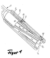
- a contact spring bushing illustrated in FIGS. 1 to 5 for electrical connectors are in an originally smooth-surfaced Strip 1 of a strip material of an electrically conductive sheet material a Variety of cutouts 2 punched out, so that between the punched out Free-cutting 2, in the embodiment shown strip-shaped, contacting 3 are retained, which have a rectangular cross-sectional shape and also at both ends via a respective edge strips 4 and 5 connected to each other stay. Together with the contacting means 3 is also at the same time a crimp connection 6 is cut free from the strip of strip material 1. The with the contact spring bushing 7 forming cut areas in one piece, crimp connections 6 forming cutting areas remain overall and constantly with one connected to a transport strip forming region of the starting material.
- the Contact spring bushing 7 is in one of its two embodiments shown in turn by a rolled-up to a cylinder body flat material portion formed, stable sleeve body 8 recorded and fixed in a form-fitting manner.
- the stable sleeve body 8 with two mutually oppositely aligned cut and the Centered through the middle of the sleeve body 8, as tongues 9 and 10 trained Provided free cuts, the tongues 9 and 10 with their free ends 11 each abut against the inner end face 12 of the edge strips 4 and 5 and such a stable axial and radial support of the contact spring bush 7 in the stable Form sleeve body 8.
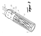
- 4 In the edge strip 4 is, as particularly clear from the representation of Figure 4 can be seen, a rectangular plan having and in the circumferential direction the edge strip 4 aligned window recess 13 recessed.
- the stable sleeve body 8 Complementary to the window recess 13 are in the stable sleeve body 8 two also aligned in the circumferential direction, arranged opposite one another and with their free ends facing each other tongues 14 and 15 cut free and with respect to the contact sleeve bent inwardly so that they are in positive engagement with the narrow side edges 16 and 17 of the window recess 13 stand.
- the two tongues 14 and 15 are shown at Embodiment in one of the two longitudinal edges 18 or 19 of the sleeve body 8 forming sheet material blank discontinuously cut free.
- Next is 5 shows that the impact edges 20 and 21 of the contact spring bush 7 forming material blank and the impact edges 18 or 19 of the sleeve body 8 forming material blank by at least 45 ° are arranged rotated against each other.
Landscapes
- Manufacturing Of Electrical Connectors (AREA)
- Coupling Device And Connection With Printed Circuit (AREA)
- Connector Housings Or Holding Contact Members (AREA)
- Connecting Device With Holders (AREA)
Abstract
Description
Die Erfindung bezieht sich auf eine Kontaktbuchse für elektrische Steckverbinder gemäß dem Oberbegriff des Anspruches 1.The invention relates to a contact socket for electrical connectors according to the preamble of claim 1.
Eine derartige Kontaktbuchse ist aus der US-PS 5 921 822 bekannt. Diese Bauart
einer Kontaktbuchse zeichnet sich dadurch aus, daß die Kontaktfederbuchse eine
Anzahl durch Ausstanzen aus einem fortlaufenden Streifen eines Kontaktmaterials
gebildete streifenförmige Kontaktierungsmittel, die untereinander durch zwei jeweils
zu einer sechseckigen Querschnittsform abgewinkelte Randstreifen verbunden
sind, aufweist, wobei resultierend aus der hexagonalen Querschnittsform der
Randstreifen nur eine sehr begrenzte Anzahl von Kontaktstreifen verwirklichbar ist,
was naturgemäß eine Verringerung der Kontaktsicherheit mit sich bringt. Im Übrigen
sind auch hier die Kontaktstreifen in bekannter und gebräuchlicher Weise insgesamt
schräg zur Längsachse der Kontaktfederbuchse ausgerichtet.
Aus der US-PS 5 921 822 ist es ferner bekannt die als solche verhältnismäßig labile
Kontaktfederbuchse in einen stabilen Hülsenkörper aufzunehmen, um eine problemlos
verwendbare Kontaktbuchse zu erhalten, ohne zugleich die Kontaktierungseigenschaften
der Kontaktfederbuchse nachteilig zu beeinträchtigen. Die
Festlegung der Kontaktfederbuchse in dem Hülsenkörper erfolgt dabei mittels einer
im Hülsenkörper parallel zu dessen Achse ausgerichtet freigeschnittenen und zum
inneren Ende des Hülsenkörpers hin zeigenden Zunge, welche bestimmungsgemäß
mit einer im Schlitzbereich des inneren Randstreifens der Kontaktfederbuchse
ausgebildeten Ausnehmung in Eingriff gelangen soll. Da hierbei die nach innen
durchgestellte Zunge des Hülsenkörpers in Auszugsrichtung eines mit der Kontaktfederbuchse
zu verbindenden Kontaktstiftes ansteifend ausgebildet bzw. angeordnet
ist, ist ihre mögliche Haltefunktion äußerst begrenzt, da sie beim Lösen von
Steckkontakten auf Biegung insbesondere beansprucht wird.
Aus der US-PS 5 474 479 ist ferner eine Anordnung zur Festlegung einer Kontaktfederbuchse
in einem Hülsenkörper bekannt, welche sich dadurch auszeichnet,
daß die Kontaktfederbuchse radial nach außen abgestellte Endbereiche der Kontaktfedern
aufweist und daß diesen an nach innen durchgestellten Verprägungen
des Hülsenkörpers ausgebildete Widerlagerflächen zugeordnet sind. Dabei sind
zum einen senkrecht zur Hülsenkörperachse ausgebildete Widerlagerflächen an
den nach innen gerichteten Durchstellung entweder überhaupt nicht oder aber nur
mit einem unzumutbar hohen Aufwand erzeugbar und neigen zum anderen die aus
einem dünnwandigen Material bestehenden Kontaktfedern zum Umknicken, so daß
in dieser Weise insgesamt und selbst bei Einsatz eines verhältnismäßig hohen
Herstellungsaufwandes keine sichere Festlegung der Kontaktfederbuchse in dem
Hülsenkörper erreicht werden kann.Such a contact socket is known from US Pat. No. 5,921,822. This type of contact socket is characterized in that the contact spring bush has a number of strip-shaped contacting means formed by punching from a continuous strip of a contact material, which are interconnected by two edge strips angled to a hexagonal cross-sectional shape, resulting in the hexagonal cross-sectional shape of the edge strips Only a very limited number of contact strips can be realized, which naturally brings about a reduction in the contact reliability. Incidentally, here too, the contact strips in a known and customary manner are aligned obliquely to the longitudinal axis of the contact spring bushing.
From US Pat. No. 5,921,822 it is also known to receive as such a relatively unstable contact spring bushing in a stable sleeve body in order to obtain a contact socket which can be used without problems, without adversely affecting the contacting properties of the contact spring bushing at the same time. The determination of the contact spring bushing in the sleeve body is effected by means of a sleeve body parallel to the axis aligned cut and the inner end of the sleeve body facing tongue, which is intended to engage with a formed in the slot portion of the inner edge strip of the contact spring socket recess. Since in this case the inserted inwardly tongue of the sleeve body in the extension direction of a contact spring to be connected to the contact pin pin is formed or arranged stiffening, their possible holding function is extremely limited, since it is particularly stressed when loosening plug contacts on bending.
From US-PS 5,474,479 an arrangement for fixing a contact spring bushing in a sleeve body is also known, which is characterized in that the contact spring bushing radially outwardly parked end portions of the contact springs and that this assigned to inwardly enforced stampings of the sleeve body formed abutment surfaces are. In this case, perpendicular to the sleeve body axis formed abutment surfaces of the inwardly directed position either not at all or only with an unreasonable high cost generated and tend to the other consisting of a thin-walled material contact springs to kinking, so that in total and in this way Use of a relatively high production costs no secure fixing of the contact spring bush in the sleeve body can be achieved.
Der Erfindung liegt daher die Aufgabe zugrunde eine preisgünstig herstellbare Kontaktbuchse der im Oberbegriff des Anspruches 1 beschriebenen Bauart für elektrische Steckverbinder aufzuzeigen, welche auf der einen Seite eine sichere Verankerung der Kontaktfederbuchse in dem stabilen Hülsenkörper gewährleistet und auf der anderen Seite auch in der mechanischen Serienfertigung leicht zu verwirklichen ist.The invention is therefore the object of an inexpensive producible Contact socket of the type described in the preamble of claim 1 for show electrical connectors, which on the one hand a secure Ensuring anchoring of the contact spring bushing in the stable sleeve body guaranteed and on the other hand also in the mechanical mass production easy to is to realize.
Diese Aufgabe wird durch die im Anspruch 1 angegebenen Merkmale gelöst.
Vorteilhafte Weiterbildungen und zweckmäßige Ausgestaltungen sind in den Unteransprüchen
angegeben.
Die erfindungsgemäß rein formschlüssige Verbindungsweise gestattet die rein mechanisch-formschlüssige
Festlegung der Kontaktfederbuchse im stabilen Hülsenkörper
eine einfache Herstellung der Kontaktbuchse insgesamt unter ausschließlicher
Anwendung von Schneid-und Formwerkzeugen, was einer Fertigung der
Kontaktbuchsen aus fortlaufenden Materialstreifen sehr entgegenkommt, insbesondere
dahingehend, daß mittels eines Stanz-und/oder Schneidwerkzeuges aus
einem fortlaufenden Materialstreifen mit einem Crimpteil zum Anschluß der Kontaktbuchse
an einen Einzelleiter einteilig Köntaktfederbuchsen freigeschnitten und
freigestanzt und anschließend bereichsweise mehr oder minder vollständig eingerollt
werden können, in der Weise, daß die die Kontaktfederbuchsen bildenden
Bereiche der Freischnitte zu einem Zylinderkörper eingerollt und die die Crimpteile
bildenden Bereiche der Freischnitte lediglich zu einem beispielsweise U-förmigen
Profilquerschnitt gebogen werden können. Die solcherart vorgefertigten Kontaktfederbuchsen
werden dann unbeschadet der Beibehaltung ihrer Verbindung mit einem
Transportstreifen in einer mechanisch herstellbaren, formschlüssigen Weise
durch gegenseitiges Verkrallen oder Verzahnen von Freischnitten und Widerlagern
mit ihrerseits durch Ablängen und Einrollen eines Blechmatterials vorgefertigten
stabilen Hülsenkörpern zu einer brauchbaren Kontakthülse verbunden, wobei die
Freischnitte vorzugsweise aber nicht ausschließlicherweise in dem stabilen Hülsenkörper
und die Widerlager entsprechend an der Kontaktfederbuchse angeordnet
bzw. ausgebildet sind. Selbstverständlich liegt auch die Umkehrung dieser
wechselweisen Anordnung von Freischnitten und Widerlagern im Bereich der vorliegenden
Erfindung.This object is achieved by the features specified in claim 1. Advantageous developments and expedient embodiments are specified in the dependent claims.
The present invention purely positive connection allows the purely mechanical-form-fitting determination of the contact bushing in the stable sleeve body a simple production of the contact socket as a whole with the exclusive use of cutting and forming tools, which very much accommodates a production of the contact sockets of continuous strips of material, in particular to the effect that by means of a punch -and / or cutting tool from a continuous strip of material with a crimp for connecting the contact socket to a single conductor one-piece Köntaktfederbuchsen cut and punched free and then partially more or less completely rolled, in such a way that the contact spring bushing forming areas of the free cuts to a cylinder body rolled up and the crimping parts forming areas of the free cuts can be bent only to an example U-shaped profile cross-section. The thus prefabricated contact spring bushes are then without prejudice to the maintenance of their connection to a transport strip in a mechanically producible, positive manner by mutual Verkrallen or teeth of cutouts and abutments in turn by cutting and rolling a Blechmatterials prefabricated stable sleeve bodies connected to a useful contact sleeve, wherein the free cuts Preferably, but not exclusively in the stable sleeve body and the abutment are arranged or formed according to the contact spring bushing. Of course, the reverse of this alternate arrangement of cutouts and abutments is also within the scope of the present invention.
In einer ersten Verwirklichungsform einer aus einer Kontaktfederbuchse und einem stabilen Hülsenkörper bestehenden Kontaktbuchse ist vorgesehen, daß in an sich bekannter Weise die Kontaktierungsmittel der Kontaktfederbuchse aus einer aus einem fortlaufenden Bandmaterial freigestanzten Kontaktstreifenfolge bestehen wobei die Konstaktstreifen beidendig untereinander über Randstreifen des fortlaufenden Bandmaterials verbunden sowie in gleichbleibenden gegenseitigen Abständen gehalten sind und daß der Hülsenkörper einen oder mehrere zungenförmige nach innen durchgestellte Freischnitte aufweist, die mit jeweils einem der beiden die Kontaktstreifen beidendig untereinander verbindenden Randstreifen im formschlüssigen Eingriff stehen. Dabei kann im Einzelnen weiter noch vorgesehen sein, daß die radial zu dessen Längsachse gerichteten zungenförmigen Freischnitte g jeweils in eine Lücke zwischen benachbarten Kontaktstreifen der Kontaktfederbuchse eingreifend formschlüssig am inneren Rand der die Kontaktstreifen beidendig untereinander verbindenden Randstreifen anliegen.In a first embodiment one of a contact spring socket and a stable sleeve body existing contact socket is provided that in in itself known manner, the contact means of the contact spring bushing from a consist of a continuous strip material punched-free contact strip sequence wherein the Konstaktstreifen at both ends with margins of the continuous Band material connected and in constant mutual distances are held and that the sleeve body one or more tongue-shaped has cutouts inside, each with one of the both the contact strips at both ends interconnecting edge strips in form-fitting engagement stand. It can be further specified in detail be that the directed radially to the longitudinal axis tongue-shaped free cuts g each in a gap between adjacent contact strips of the contact spring socket engaging positively on the inner edge of the contact strips at both ends rest against each other connecting edge strips.
Gemäß einer zweiten Verwirklichungsform einer aus einer Kontaktfederbuchse und einem stabilen Hülsenkörper bestehenden Kontaktbuchse kann aber auch vorgesehen sein, daß mindestens einer der beiden die Kontaktstreifen der Kontaktfederbuchse beidendig untereinander verbindenden Randstreifen mit einer Fensterausnehmung versehen ist und der Hülsenkörper wenigstens eine freigeschnittene und mit der Fensterausnehmung im formschlüssigen Eingriff stehende Zunge aufweist.According to a second embodiment of a form of a contact spring socket and However, a stable sleeve body existing contact socket can also be provided be that at least one of the two contact strips of the contact spring socket at both ends interconnecting edge strips with a window recess is provided and the sleeve body at least one cut and having tongue with the window recess in positive engagement.
Die Fensterausnehmung ist vorteilhafterweise in dem dem freien Ende der Kontaktbuchse gegenüberliegenden Randstreifen angeordnet und in Umfangsrichtung der Kontaktfederbuchse ausgerichtet, so daß die formschlüssige Verbindung zwischen Kontaktfederbuchse und stabilem Hülsenkörper zum Bereich des Anschlusses der Kontaktbuchse an den Einzelleiter hin verlagert ist.The window recess is advantageously in the free end of the contact socket arranged opposite edge strips and in the circumferential direction the contact spring bushing aligned so that the positive connection between Contact spring bushing and sturdy sleeve body to the area of the terminal the contact socket is shifted towards the individual conductor.
Eine vorteilhafte Gestaltungsweise der formschlüssigen Verbindung der Kontaktfederbuchse mit dem Stabilen Hülsenkörper besteht darin, daß die in dem dem freien Ende der Kontaktbuchse gegenüberliegenden Randstreifen der Kontaktfederbuchse angeordnete Fensterausnehmung eine rechteckige Grundrißform aufweist und im Hülsenkörper zwei einander gegenüberliegende und nach innen abgewinkelte Zungen freigeschnitten sind, welche mit den Schmalseiten der Fensterausnehmung im formschlüssigen Eingriff stehen. Diese Ausbildung ist insbesondere dort von besonderem Vorteil, wo im Weiteren vorgesehen ist, daß die beiden im Hülsenkörper freigeschnittenen Zungen gegeneinander zeigend ausgerichtet und jede der beiden Zungen in einen der beiden Längsränder des den Hülsenkörper bildenden Blechmaterialzuschnittes auslaufend freigeschnitten ist. An advantageous design of the positive connection of the contact spring socket with the stable sleeve body is that in which the free End of the contact socket opposite edge strip of the contact spring bushing arranged window recess has a rectangular planform and in the sleeve body two opposing and angled inward Tongues are cut free, which with the narrow sides of the window recess in positive engagement. This training is especially there of particular advantage, where it is further provided that the two in the sleeve body aligned tongues aligned against each other and each of the two tongues in one of the two longitudinal edges of the sleeve body forming Sheet material blank is cut open expiring.
In weiterer vorteilhafter Ausgestaltung wird noch vorgeschlagen, daß die Stoßränder des die Kontaktfederbuchse bildenden Materialzuschnittes und des den Hülsenkörper bildenden Materialzuschnittes um wenigstens 45° gegeneinander verdreht angeordnet sind.In a further advantageous embodiment, it is also proposed that the impact edges of the contact spring bush forming material blank and the sleeve body forming material blank rotated by at least 45 ° from each other are arranged.
Die Erfindung ist in der nachfolgenden Beispielsbeschreibung anhand zweier in der Zeichnung dargestellter Ausführungsbeispiele im Einzelnen beschrieben. In der Zeichnung zeigt die
- Figur 1
- eine teilweise aufgeschnittene schaubildliche Darstellung einer ersten Verwirklichungsform einer Kontaktbuchse;
Figur 2- eine schaubildliche Darstellung einer zweiten Verwirklichungsform einer Kontaktbuchse;
- Figur 3
- eine aufgeschnittene Darstellung der zweiten Verwirklichungsform nach
Figur 2; Figur 4- eine schaubildliche Einzeldarstellung einer Kontaktfederbuchse mit angeformtem Crimpteil;
Figur 5- eine schaubildliche Darstellung der Lage einer Kontaktfederbuchse in einem stabilen Hülsenkörper.
- FIG. 1
- a partially cutaway perspective view of a first embodiment of a contact socket;
- FIG. 2
- a perspective view of a second embodiment of a contact socket;
- FIG. 3
- a cutaway view of the second embodiment of Figure 2;
- FIG. 4
- a perspective individual view of a contact spring socket with molded crimp;
- FIG. 5
- a perspective view of the position of a contact spring bush in a stable sleeve body.
Bei allen in den Figuren 1 bis 5 dargestellten Ausführungsformen einer Kontaktfederbuchse
für elektrische Steckverbinder sind in einem ursprünglich glattflächigen
Streifen 1 eines Bandmaterials aus einem elektrisch leitenden Blechmaterial eine
Vielzahl von Freischnitten 2 ausgestanzt, derart, daß zwischen den ausgestanzten
Freischnitten 2, in der gezeigten Ausführungsform streifenförmige, Kontaktierungsmittel
3 erhalten bleiben, welche eine rechteckige Querschnittsform aufweisen
und zudem beidendig über je einem Randstreifen 4 bzw. 5 miteinander verbunden
bleiben. Zusammen mit den Kontaktierungsmitteln 3 wird gleichzeitig auch
ein Crimpanschluß 6 aus dem Bandmaterialstreifen 1 freigeschnitten. Die mit den
die Kontaktfederbuchse 7 bildenden Zuschnittsbereichen einteiligen, Crimpanschlüsse
6 bildenden Zuschnittsbereiche bleiben insgesamt und ständig mit einem
einen Transportstreifen bildenden Bereich des Ausgangsmaterials verbunden. Die
Kontaktfederbuchse 7 ist in beiden gezeigten Ausführungsformen in einem seinerseits
durch einen zu einem Zylinderkörper eingerollten Flachmaterialabschnitt
gebildeten, stabilen Hülsenkörper 8 aufgenommen und formschlüssig festgelegt.
Gemäß der in der Figur 1 gezeigten Ausführungsform ist der stabile Hülsenkörper
8 mit zwei zueinander entgegengesetzt ausgerichtet freigeschnittenen und zur
Mitte des Hülsenkörpers 8 hin durchgestellten, als Zungen 9 und 10 ausgebildeten
Freischnitten versehen, wobei die Zungen 9 und 10 mit ihren freien Enden 11 jeweils
an der innenliegenden Stirnfläche 12 der Randstreifen 4 bzw. 5 anliegen und
so eine stabile axiale und radiale Abstützung der Kontaktfederbuchse 7 im stabilen
Hülsenkörper 8 bilden. In all embodiments of a contact spring bushing illustrated in FIGS. 1 to 5
for electrical connectors are in an originally smooth-surfaced
Strip 1 of a strip material of an electrically conductive sheet material a
Variety of
Bei der in den Figuren 2 bis 5 dargestellten Ausführungsform sind die die Kontaktierungsmittel
3 untereinander verbindenden Randstreifen 4 bzw. 5 von deren einem
freien zu deren anderen dem Crimpanschluß 6 benachbarten Ende der Kontaktfederbuchse
7 hin unterschiedlich breit ausgeführt und zwar derart, daß der
dem Crimpanschluß 6 benachbarte Randstreifen 5 eine größere axiale Erstreckung
aufweist als der dem freien Ende der Kontaktbuchse zugewandte Randstreifen 4.
In dem Randstreifen 4 ist, wie besonders deutlich aus der Darstellung der Figur 4
ersichtlich, eine einen rechteckigen Grundriß aufweisende sowie in Umfangsrichtung
des Randstreifen 4 ausgerichtete Fensterausnehmung 13 ausgespart. Komplementär
zur Fensterausnehmung 13 sind in dem stabilen Hülsenkörper 8 zwei
gleichfalls in Umfangsrichtung ausgerichtete, einander gegenüberliegend angeordnete
und mit ihren freien Enden zueinander zeigende Zungen 14 und 15 freigeschnitten
und bezüglich der Kontakthülse derart nach innen gebogen, daß sie im
formschlüssigen Eingriff mit den schmalseitigen Rändern 16 und 17 der Fensterausnehmung
13 stehen. Die beiden Zungen 14 und 15 sind bei der gezeigten
Ausführungsform in einen der beiden Längsränder 18 oder 19 des den Hülsenkörper
8 bildenden Blechmaterialzuschnittes auslaufend freigeschnitten. Weiter ist
aus der Darstellung der Figur 5 noch ersichtlich, daß die Stoßränder 20 und 21
des die Kontaktfederbuchse 7 bildenden Materialzuschnittes und die Stoßränder
18 oder 19 des den Hülsenkörper 8 bildenden Materialzuschnittes um wenigstens
45° gegeneinander verdreht angeordnet sind. Insbesondere aus den Figuren 2 und
3 ist darüber hinaus besonders deutlich ersichtlich, daß die in die beiden Längsränder
18 und 19 auslaufenden Zungen 14 und 15 des stabilen Hülsenkörpers 8
entlang ihrer beiden Längsseiten jeweils mit einem breiten, eine bequemen Werzeugansatz
gewährleistenden Freischnittraum 22, 23 freigeschnitten sind.In the embodiment illustrated in FIGS. 2 to 5, these are the contacting means
3 interconnecting
Claims (6)
- Contact socket for electrical connector comprising a strong sleeve body (8) made of a sheet metal material and a contact spring socket (7) embedded therein and comprising a plurality of contacting means, such as contact wires or contact strips coming into linear or strip-like contact with a contact pin to be inserted into the socket, wherein the contact wires or contact strips (3) of the contact spring socket (7) are oriented in twisted manner around the socket axis and connected on both ends to an edge strip (4 or 5, respectively) made of sheet metal, and wherein the contact spring socket (7) is further mechanically and electronically connected to the sleeve body (8), wherein the sleeve body (8) is provided with a stamp, which is associated with a recess in one of the edge strips (5) of the contact spring socket (7),
characterised in that
the stamp in the sleeve body (8) is formed by at least one tongue-shaped and inwardly arranged cut-free part (9 or 10, respectively), transversely oriented to the longitudinal axis of the contact spring socket (7), and the at least one tongue-shaped cut-free part (9 or 10, respectively) is in form-locking engagement with a window recess (13) provided in one of the two edge strips (4, 5) rolled to a cylinder body, which connect the contact wires or contacts strips (3) of the contact spring socket (7) with each other. - Contact socket according to claim 1, characterised in that the contacting means (3) of the contact spring socket (7) are made of a contact strip sequence punched out off a continuous sheet material (1) and are mutually connected on both ends through edge strips (4 and 5) of the continuous sheet material (1) and are kept in the same distances from each other, and that the sleeve body (8) comprises two tongue-shaped cut-free parts (4 and 5) spaced apart in the axial direction, each of which is in form-locking engagement with respectively one window recess (13) provided in one of the two edge strips (4 or 5) rolled to a cylinder body.
- Contact socket according to claims 1 and 2, characterised in that the window recess (13) is arranged in the edge strip (5) opposite the free end of the contact spring socket (7) and is oriented in the circumferential direction of the contact spring socket (7).
- Contact socket according to claims 1 to 3, characterised in that the window recess (13) arranged in the edge strip (5) of the contact spring socket (7) opposed to the free end of the contact spring socket (7) comprises a rectangular plan form, and that in the sleeve body (8) two tongues (14 and 14) opposed to each other and angled inwardly are cut free, which are in form-locking engagement with the narrow sides of the window recess (13).
- Contact socket according to claims 1 to 4, characterised in that the two tongues (14 and 15) cut free in the sleeve body (8) are oriented facing each other, and that each of the two tongues (14 and 15) is cut free running out into one of the two longitudinal edges of the sheet metal material blanks forming the sleeve body (8).
- Contact socket according to one of the preceding claims 1 to 5, characterised in that the abutment edges (20 and 21) of the material blank forming the contact spring socket (7) and of the material blank forming the sleeve body (8) are arranged twisted with regard to each other by at least 45°.
Applications Claiming Priority (2)
| Application Number | Priority Date | Filing Date | Title |
|---|---|---|---|
| DE19933091A DE19933091A1 (en) | 1999-07-15 | 1999-07-15 | Contact socket for electrical connectors |
| DE19933091 | 1999-07-15 |
Publications (2)
| Publication Number | Publication Date |
|---|---|
| EP1069652A1 EP1069652A1 (en) | 2001-01-17 |
| EP1069652B1 true EP1069652B1 (en) | 2003-09-17 |
Family
ID=7914832
Family Applications (1)
| Application Number | Title | Priority Date | Filing Date |
|---|---|---|---|
| EP00114141A Expired - Lifetime EP1069652B1 (en) | 1999-07-15 | 2000-07-11 | Female contact for electrical connectors |
Country Status (4)
| Country | Link |
|---|---|
| US (1) | US6425786B1 (en) |
| EP (1) | EP1069652B1 (en) |
| AT (1) | ATE250286T1 (en) |
| DE (2) | DE19933091A1 (en) |
Cited By (1)
| Publication number | Priority date | Publication date | Assignee | Title |
|---|---|---|---|---|
| CN108475867A (en) * | 2015-12-15 | 2018-08-31 | 安费诺-图赫尔电子有限公司 | Radially contact with socket |
Families Citing this family (18)
| Publication number | Priority date | Publication date | Assignee | Title |
|---|---|---|---|---|
| JP2004509440A (en) * | 2000-09-15 | 2004-03-25 | アルコア フジクラ リミテッド | Electrical terminal socket assembly for vehicle parts |
| US6860768B2 (en) * | 2000-09-15 | 2005-03-01 | Alcoa Fujikura Limited | Combination sleeve and spring cage incorporated into a one-piece female terminal for interengaging a corresponding male terminal and method of configuring such a sleeve and spring cage from a blank shape |
| US6656002B2 (en) * | 2000-09-15 | 2003-12-02 | Alcoa Fujikura Limited | Electrical terminal socket assembly including T shaped sealed connectors |
| DE10235058A1 (en) * | 2002-07-31 | 2004-02-12 | Siemens Ag | Removable electrical contact in which there is a sleeve element that is fitted onto the end of a contact bush and is retained by applying a turning moment |
| DE10235053A1 (en) * | 2002-07-31 | 2004-02-12 | Siemens Ag | Manufacture of an electrical contact in which there is a sleeve element that is fitted onto the end of a contact bush and is laser welded |
| US6848922B2 (en) * | 2003-03-10 | 2005-02-01 | Hypertronics Corporation | Socket contact with integrally formed arc arresting portion |
| US6997750B2 (en) * | 2003-07-23 | 2006-02-14 | Fci Americas Technology, Inc. | Electrical connector contact |
| DE102005043692A1 (en) * | 2005-09-14 | 2007-03-15 | Robert Bosch Gmbh | Electrical connector with preloaded contact blades |
| WO2007084085A2 (en) * | 2006-01-19 | 2007-07-26 | Mkem, Spol. S R.O. | Contact tube with lamella |
| CH704749B1 (en) * | 2007-09-05 | 2012-10-15 | Preci Dip Sa | contact clip. |
| DE202010003649U1 (en) * | 2010-03-16 | 2010-07-15 | Rosenberger Hochfrequenztechnik Gmbh & Co. Kg | High Power Connectors |
| DE102011054316B4 (en) * | 2011-10-07 | 2021-04-01 | Te Connectivity Germany Gmbh | Two-part crimp contact element |
| US20150244096A1 (en) * | 2014-02-27 | 2015-08-27 | Amphenol Corporation | Electrical socket with improved misalignment tolerance |
| WO2018063928A1 (en) * | 2016-09-30 | 2018-04-05 | Molex, Llc | Socket connector |
| CN106684603A (en) * | 2017-03-03 | 2017-05-17 | 王轶 | A compact receptacle connector with torsion spring contacts |
| CN108365371B (en) * | 2017-11-07 | 2020-10-02 | 得意精密电子(苏州)有限公司 | Electric connector and manufacturing method thereof |
| CN108110469B (en) * | 2018-01-26 | 2024-04-05 | 深圳市特拉利线簧端子技术有限公司 | Metal reed, jack assembly and electric connector |
| US10541489B2 (en) | 2018-03-29 | 2020-01-21 | Amphenol Corporation | Electrical socket with contoured contact beams |
Family Cites Families (13)
| Publication number | Priority date | Publication date | Assignee | Title |
|---|---|---|---|---|
| US4128293A (en) * | 1977-11-02 | 1978-12-05 | Akzona Incorporated | Conductive strip |
| DE2852267C2 (en) * | 1978-12-02 | 1982-02-18 | Wampfler Gmbh, 7858 Weil | Connection device for conductor rails |
| DE3531845C2 (en) * | 1985-09-06 | 1994-05-26 | Daut & Rietz Trw | Contact part, shaped as a socket or plug part for insertion in socket or plug housings |
| DE3625384A1 (en) * | 1986-07-26 | 1988-02-04 | Reinshagen Kabelwerk Gmbh | ELECTRICAL CONNECTOR |
| US4973272A (en) * | 1987-01-30 | 1990-11-27 | Wyle Laboratories | Electrical connector with contactors |
| US5147230A (en) * | 1991-12-19 | 1992-09-15 | General Motors Corporation | Two piece electrical female terminal |
| DE4203379A1 (en) * | 1992-02-06 | 1993-08-12 | Daut & Rietz Trw | U=shaped spring contact for electric flat connector - has openings in strips along base of upper spring element giving clearance for deflection of contact arms |
| US5474479A (en) * | 1994-09-28 | 1995-12-12 | The Whitaker Corporation | Louvered contact electrical connector |
| US6139374A (en) * | 1995-07-25 | 2000-10-31 | Framatome Connectors Interlock Inc. | Connector assembly |
| US5810627A (en) * | 1996-01-11 | 1998-09-22 | Molex Incorporated | Female electrical terminal |
| FR2758213B1 (en) * | 1997-01-07 | 1999-01-29 | Cinch Connecteurs Sa | FEMALE ELECTRIC CONTACT MEMBER |
| US6062919A (en) * | 1997-08-29 | 2000-05-16 | Thomas & Betts International, Inc. | Electrical connector assembly having high current-carrying capability and low insertion force |
| DE19802821B4 (en) * | 1998-01-26 | 2008-02-07 | The Whitaker Corp., Wilmington | Electrical connection terminal |
-
1999
- 1999-07-15 DE DE19933091A patent/DE19933091A1/en not_active Withdrawn
-
2000
- 2000-07-11 AT AT00114141T patent/ATE250286T1/en active
- 2000-07-11 DE DE50003701T patent/DE50003701D1/en not_active Expired - Lifetime
- 2000-07-11 EP EP00114141A patent/EP1069652B1/en not_active Expired - Lifetime
- 2000-07-12 US US09/614,315 patent/US6425786B1/en not_active Expired - Lifetime
Cited By (1)
| Publication number | Priority date | Publication date | Assignee | Title |
|---|---|---|---|---|
| CN108475867A (en) * | 2015-12-15 | 2018-08-31 | 安费诺-图赫尔电子有限公司 | Radially contact with socket |
Also Published As
| Publication number | Publication date |
|---|---|
| DE19933091A1 (en) | 2001-02-01 |
| DE50003701D1 (en) | 2003-10-23 |
| ATE250286T1 (en) | 2003-10-15 |
| EP1069652A1 (en) | 2001-01-17 |
| US6425786B1 (en) | 2002-07-30 |
Similar Documents
| Publication | Publication Date | Title |
|---|---|---|
| EP1069652B1 (en) | Female contact for electrical connectors | |
| EP1103088B1 (en) | Bushing contact | |
| EP3316402A1 (en) | Flat contact bushing | |
| DE9217310U1 (en) | Electrical connection with means for fixing contacts | |
| EP1081796A1 (en) | High current contact | |
| DE10351540B3 (en) | Flat plug socket | |
| EP3196981A1 (en) | Crosswise connector for in-line terminals | |
| EP0536523B1 (en) | Terminal | |
| DE3116731C2 (en) | Contact element | |
| EP0198408B1 (en) | Tool for manufacturing an electrical contact pin for printed-circuit boards | |
| DE19850521C1 (en) | Electrical connector | |
| DE102005017988B3 (en) | Electric contact sleeve has band bent to close off inner space of contact sleeve | |
| EP1587172B1 (en) | Female terminal for the electrically conductive connection to a terminal pin, in particular a flat terminal pin | |
| DE102005063286A1 (en) | Contact socket for a pin | |
| DE69503902T2 (en) | CONTACT FOR CUTTING CLAMP CONNECTORS | |
| EP1248318B1 (en) | Electrical contact as well as lamphoder and connecting terminal with at least such a contact | |
| EP1763111B1 (en) | Socket contact with at least two contact points in the plug direction | |
| EP4205240A1 (en) | Electric contact, in particular flat contact or bifurcated contact | |
| EP0650222B1 (en) | Female terminal for an electrical connection of flat contact pins | |
| DE9304392U1 (en) | Contact element with insulation displacement and crimp connection | |
| DE29805916U1 (en) | Contact socket for electrical connectors | |
| EP1312139A1 (en) | Jack for a plug-jack combination | |
| EP1164662B1 (en) | Socket contact | |
| EP0922314B1 (en) | Female connector part for electric pin-and-socket connector | |
| DE29912351U1 (en) | Contact socket for electrical connectors |
Legal Events
| Date | Code | Title | Description |
|---|---|---|---|
| PUAI | Public reference made under article 153(3) epc to a published international application that has entered the european phase |
Free format text: ORIGINAL CODE: 0009012 |
|
| AK | Designated contracting states |
Kind code of ref document: A1 Designated state(s): AT BE CH CY DE DK ES FI FR GB GR IE IT LI LU MC NL PT SE |
|
| AX | Request for extension of the european patent |
Free format text: AL;LT;LV;MK;RO;SI |
|
| 17P | Request for examination filed |
Effective date: 20010306 |
|
| AKX | Designation fees paid |
Free format text: AT BE CH CY DE DK ES FI FR GB GR IE IT LI LU MC NL PT SE |
|
| GRAH | Despatch of communication of intention to grant a patent |
Free format text: ORIGINAL CODE: EPIDOS IGRA |
|
| 17Q | First examination report despatched |
Effective date: 20021202 |
|
| GRAH | Despatch of communication of intention to grant a patent |
Free format text: ORIGINAL CODE: EPIDOS IGRA |
|
| GRAA | (expected) grant |
Free format text: ORIGINAL CODE: 0009210 |
|
| AK | Designated contracting states |
Kind code of ref document: B1 Designated state(s): AT BE CH CY DE DK ES FI FR GB GR IE IT LI LU MC NL PT SE |
|
| PG25 | Lapsed in a contracting state [announced via postgrant information from national office to epo] |
Ref country code: IE Free format text: LAPSE BECAUSE OF FAILURE TO SUBMIT A TRANSLATION OF THE DESCRIPTION OR TO PAY THE FEE WITHIN THE PRESCRIBED TIME-LIMIT Effective date: 20030917 Ref country code: CY Free format text: LAPSE BECAUSE OF FAILURE TO SUBMIT A TRANSLATION OF THE DESCRIPTION OR TO PAY THE FEE WITHIN THE PRESCRIBED TIME-LIMIT Effective date: 20030917 Ref country code: FI Free format text: LAPSE BECAUSE OF FAILURE TO SUBMIT A TRANSLATION OF THE DESCRIPTION OR TO PAY THE FEE WITHIN THE PRESCRIBED TIME-LIMIT Effective date: 20030917 Ref country code: NL Free format text: LAPSE BECAUSE OF FAILURE TO SUBMIT A TRANSLATION OF THE DESCRIPTION OR TO PAY THE FEE WITHIN THE PRESCRIBED TIME-LIMIT Effective date: 20030917 |
|
| REG | Reference to a national code |
Ref country code: GB Ref legal event code: FG4D Free format text: NOT ENGLISH |
|
| REG | Reference to a national code |
Ref country code: CH Ref legal event code: EP |
|
| REF | Corresponds to: |
Ref document number: 50003701 Country of ref document: DE Date of ref document: 20031023 Kind code of ref document: P |
|
| REG | Reference to a national code |
Ref country code: IE Ref legal event code: FG4D Free format text: GERMAN |
|
| PG25 | Lapsed in a contracting state [announced via postgrant information from national office to epo] |
Ref country code: GR Free format text: LAPSE BECAUSE OF FAILURE TO SUBMIT A TRANSLATION OF THE DESCRIPTION OR TO PAY THE FEE WITHIN THE PRESCRIBED TIME-LIMIT Effective date: 20031217 Ref country code: SE Free format text: LAPSE BECAUSE OF FAILURE TO SUBMIT A TRANSLATION OF THE DESCRIPTION OR TO PAY THE FEE WITHIN THE PRESCRIBED TIME-LIMIT Effective date: 20031217 Ref country code: DK Free format text: LAPSE BECAUSE OF FAILURE TO SUBMIT A TRANSLATION OF THE DESCRIPTION OR TO PAY THE FEE WITHIN THE PRESCRIBED TIME-LIMIT Effective date: 20031217 |
|
| PG25 | Lapsed in a contracting state [announced via postgrant information from national office to epo] |
Ref country code: PT Free format text: LAPSE BECAUSE OF FAILURE TO SUBMIT A TRANSLATION OF THE DESCRIPTION OR TO PAY THE FEE WITHIN THE PRESCRIBED TIME-LIMIT Effective date: 20031226 |
|
| PG25 | Lapsed in a contracting state [announced via postgrant information from national office to epo] |
Ref country code: ES Free format text: LAPSE BECAUSE OF FAILURE TO SUBMIT A TRANSLATION OF THE DESCRIPTION OR TO PAY THE FEE WITHIN THE PRESCRIBED TIME-LIMIT Effective date: 20031228 |
|
| REG | Reference to a national code |
Ref country code: CH Ref legal event code: NV Representative=s name: KIRKER & CIE SA Ref country code: CH Ref legal event code: PFA Owner name: HYPERTAC GMBH Free format text: INTERCONNECTRON GMBH#AUWIESENSTRASSE 5#94469 DEGGENDORF (DE) -TRANSFER TO- HYPERTAC GMBH#AUWIESENSTRASSE 5#94469 DEGGENDORF (DE) |
|
| GBT | Gb: translation of ep patent filed (gb section 77(6)(a)/1977) |
Effective date: 20040104 |
|
| RAP2 | Party data changed (patent owner data changed or rights of a patent transferred) |
Owner name: HYPERTAC GMBH |
|
| NLV1 | Nl: lapsed or annulled due to failure to fulfill the requirements of art. 29p and 29m of the patents act | ||
| REG | Reference to a national code |
Ref country code: IE Ref legal event code: FD4D |
|
| ET | Fr: translation filed | ||
| PG25 | Lapsed in a contracting state [announced via postgrant information from national office to epo] |
Ref country code: LU Free format text: LAPSE BECAUSE OF NON-PAYMENT OF DUE FEES Effective date: 20040711 |
|
| PLBE | No opposition filed within time limit |
Free format text: ORIGINAL CODE: 0009261 |
|
| STAA | Information on the status of an ep patent application or granted ep patent |
Free format text: STATUS: NO OPPOSITION FILED WITHIN TIME LIMIT |
|
| PG25 | Lapsed in a contracting state [announced via postgrant information from national office to epo] |
Ref country code: MC Free format text: LAPSE BECAUSE OF NON-PAYMENT OF DUE FEES Effective date: 20040731 Ref country code: BE Free format text: LAPSE BECAUSE OF NON-PAYMENT OF DUE FEES Effective date: 20040731 |
|
| 26N | No opposition filed |
Effective date: 20040618 |
|
| BERE | Be: lapsed |
Owner name: *INTERCONNECTRON G.M.B.H. Effective date: 20040731 |
|
| BERE | Be: lapsed |
Owner name: *INTERCONNECTRON G.M.B.H. Effective date: 20040731 |
|
| REG | Reference to a national code |
Ref country code: FR Ref legal event code: CD |
|
| REG | Reference to a national code |
Ref country code: FR Ref legal event code: PLFP Year of fee payment: 17 |
|
| REG | Reference to a national code |
Ref country code: FR Ref legal event code: PLFP Year of fee payment: 18 |
|
| PGFP | Annual fee paid to national office [announced via postgrant information from national office to epo] |
Ref country code: CH Payment date: 20170712 Year of fee payment: 18 |
|
| PGFP | Annual fee paid to national office [announced via postgrant information from national office to epo] |
Ref country code: AT Payment date: 20170626 Year of fee payment: 18 |
|
| REG | Reference to a national code |
Ref country code: FR Ref legal event code: PLFP Year of fee payment: 19 |
|
| REG | Reference to a national code |
Ref country code: CH Ref legal event code: PL |
|
| REG | Reference to a national code |
Ref country code: AT Ref legal event code: MM01 Ref document number: 250286 Country of ref document: AT Kind code of ref document: T Effective date: 20180711 |
|
| PG25 | Lapsed in a contracting state [announced via postgrant information from national office to epo] |
Ref country code: CH Free format text: LAPSE BECAUSE OF NON-PAYMENT OF DUE FEES Effective date: 20180731 Ref country code: AT Free format text: LAPSE BECAUSE OF NON-PAYMENT OF DUE FEES Effective date: 20180711 Ref country code: LI Free format text: LAPSE BECAUSE OF NON-PAYMENT OF DUE FEES Effective date: 20180731 |
|
| PGFP | Annual fee paid to national office [announced via postgrant information from national office to epo] |
Ref country code: FR Payment date: 20190619 Year of fee payment: 20 |
|
| PGFP | Annual fee paid to national office [announced via postgrant information from national office to epo] |
Ref country code: DE Payment date: 20190625 Year of fee payment: 20 Ref country code: IT Payment date: 20190719 Year of fee payment: 20 |
|
| PGFP | Annual fee paid to national office [announced via postgrant information from national office to epo] |
Ref country code: GB Payment date: 20190710 Year of fee payment: 20 |
|
| REG | Reference to a national code |
Ref country code: DE Ref legal event code: R071 Ref document number: 50003701 Country of ref document: DE |
|
| REG | Reference to a national code |
Ref country code: GB Ref legal event code: PE20 Expiry date: 20200710 |
|
| PG25 | Lapsed in a contracting state [announced via postgrant information from national office to epo] |
Ref country code: GB Free format text: LAPSE BECAUSE OF EXPIRATION OF PROTECTION Effective date: 20200710 |