EP1069483B1 - Entwicklungsgerät - Google Patents
Entwicklungsgerät Download PDFInfo
- Publication number
- EP1069483B1 EP1069483B1 EP00115145A EP00115145A EP1069483B1 EP 1069483 B1 EP1069483 B1 EP 1069483B1 EP 00115145 A EP00115145 A EP 00115145A EP 00115145 A EP00115145 A EP 00115145A EP 1069483 B1 EP1069483 B1 EP 1069483B1
- Authority
- EP
- European Patent Office
- Prior art keywords
- developer
- developing
- toner
- developing apparatus
- layer thickness
- Prior art date
- Legal status (The legal status is an assumption and is not a legal conclusion. Google has not performed a legal analysis and makes no representation as to the accuracy of the status listed.)
- Expired - Lifetime
Links
- 238000000034 method Methods 0.000 claims description 18
- 230000001105 regulatory effect Effects 0.000 claims description 17
- 230000008569 process Effects 0.000 claims description 5
- 229920002379 silicone rubber Polymers 0.000 claims description 3
- 239000004945 silicone rubber Substances 0.000 claims description 3
- 230000004323 axial length Effects 0.000 claims description 2
- IPZIVCLZBFDXTA-UHFFFAOYSA-N ethyl n-prop-2-enoylcarbamate Chemical compound CCOC(=O)NC(=O)C=C IPZIVCLZBFDXTA-UHFFFAOYSA-N 0.000 claims description 2
- 229920002803 thermoplastic polyurethane Polymers 0.000 claims description 2
- 239000010410 layer Substances 0.000 description 21
- 230000002093 peripheral effect Effects 0.000 description 8
- 238000010276 construction Methods 0.000 description 6
- 229910052751 metal Inorganic materials 0.000 description 6
- 239000002184 metal Substances 0.000 description 6
- 230000000379 polymerizing effect Effects 0.000 description 6
- 230000014509 gene expression Effects 0.000 description 5
- 238000004140 cleaning Methods 0.000 description 4
- 238000004519 manufacturing process Methods 0.000 description 4
- 239000002245 particle Substances 0.000 description 4
- 229910052782 aluminium Inorganic materials 0.000 description 3
- XAGFODPZIPBFFR-UHFFFAOYSA-N aluminium Chemical compound [Al] XAGFODPZIPBFFR-UHFFFAOYSA-N 0.000 description 3
- 230000018109 developmental process Effects 0.000 description 3
- 239000000463 material Substances 0.000 description 3
- 238000005259 measurement Methods 0.000 description 3
- 239000000725 suspension Substances 0.000 description 3
- 238000011144 upstream manufacturing Methods 0.000 description 3
- VYPSYNLAJGMNEJ-UHFFFAOYSA-N Silicium dioxide Chemical compound O=[Si]=O VYPSYNLAJGMNEJ-UHFFFAOYSA-N 0.000 description 2
- PPBRXRYQALVLMV-UHFFFAOYSA-N Styrene Chemical compound C=CC1=CC=CC=C1 PPBRXRYQALVLMV-UHFFFAOYSA-N 0.000 description 2
- 230000009471 action Effects 0.000 description 2
- 238000005513 bias potential Methods 0.000 description 2
- 239000003795 chemical substances by application Substances 0.000 description 2
- 230000000694 effects Effects 0.000 description 2
- 229920001971 elastomer Polymers 0.000 description 2
- 239000000178 monomer Substances 0.000 description 2
- 239000002699 waste material Substances 0.000 description 2
- XLYOFNOQVPJJNP-UHFFFAOYSA-N water Substances O XLYOFNOQVPJJNP-UHFFFAOYSA-N 0.000 description 2
- 229910000906 Bronze Inorganic materials 0.000 description 1
- JOYRKODLDBILNP-UHFFFAOYSA-N Ethyl urethane Chemical compound CCOC(N)=O JOYRKODLDBILNP-UHFFFAOYSA-N 0.000 description 1
- 239000004677 Nylon Substances 0.000 description 1
- OAICVXFJPJFONN-UHFFFAOYSA-N Phosphorus Chemical compound [P] OAICVXFJPJFONN-UHFFFAOYSA-N 0.000 description 1
- 229920005830 Polyurethane Foam Polymers 0.000 description 1
- 229920000297 Rayon Polymers 0.000 description 1
- 229920006311 Urethane elastomer Polymers 0.000 description 1
- 238000004458 analytical method Methods 0.000 description 1
- 230000008901 benefit Effects 0.000 description 1
- 230000015572 biosynthetic process Effects 0.000 description 1
- 239000010974 bronze Substances 0.000 description 1
- CQEYYJKEWSMYFG-UHFFFAOYSA-N butyl acrylate Chemical compound CCCCOC(=O)C=C CQEYYJKEWSMYFG-UHFFFAOYSA-N 0.000 description 1
- 230000008859 change Effects 0.000 description 1
- 239000003086 colorant Substances 0.000 description 1
- 230000001276 controlling effect Effects 0.000 description 1
- KUNSUQLRTQLHQQ-UHFFFAOYSA-N copper tin Chemical compound [Cu].[Sn] KUNSUQLRTQLHQQ-UHFFFAOYSA-N 0.000 description 1
- 239000006185 dispersion Substances 0.000 description 1
- 238000009826 distribution Methods 0.000 description 1
- 239000000839 emulsion Substances 0.000 description 1
- 230000002708 enhancing effect Effects 0.000 description 1
- 239000000835 fiber Substances 0.000 description 1
- 238000000445 field-emission scanning electron microscopy Methods 0.000 description 1
- 239000010419 fine particle Substances 0.000 description 1
- 230000012447 hatching Effects 0.000 description 1
- 230000002209 hydrophobic effect Effects 0.000 description 1
- 230000001050 lubricating effect Effects 0.000 description 1
- 229920001778 nylon Polymers 0.000 description 1
- 239000003960 organic solvent Substances 0.000 description 1
- 229920000728 polyester Polymers 0.000 description 1
- 229920000642 polymer Polymers 0.000 description 1
- 238000006116 polymerization reaction Methods 0.000 description 1
- 229920001296 polysiloxane Polymers 0.000 description 1
- 239000011496 polyurethane foam Substances 0.000 description 1
- 239000000843 powder Substances 0.000 description 1
- 239000002964 rayon Substances 0.000 description 1
- 239000011347 resin Substances 0.000 description 1
- 229920005989 resin Polymers 0.000 description 1
- 229960001860 salicylate Drugs 0.000 description 1
- -1 salicylate compound Chemical class 0.000 description 1
- 238000005070 sampling Methods 0.000 description 1
- 229920006395 saturated elastomer Polymers 0.000 description 1
- 238000007790 scraping Methods 0.000 description 1
- 239000000377 silicon dioxide Substances 0.000 description 1
- 239000000126 substance Substances 0.000 description 1
- 239000002344 surface layer Substances 0.000 description 1
Images

Classifications
-
- G—PHYSICS
- G03—PHOTOGRAPHY; CINEMATOGRAPHY; ANALOGOUS TECHNIQUES USING WAVES OTHER THAN OPTICAL WAVES; ELECTROGRAPHY; HOLOGRAPHY
- G03G—ELECTROGRAPHY; ELECTROPHOTOGRAPHY; MAGNETOGRAPHY
- G03G15/00—Apparatus for electrographic processes using a charge pattern
- G03G15/06—Apparatus for electrographic processes using a charge pattern for developing
- G03G15/08—Apparatus for electrographic processes using a charge pattern for developing using a solid developer, e.g. powder developer
- G03G15/0806—Apparatus for electrographic processes using a charge pattern for developing using a solid developer, e.g. powder developer on a donor element, e.g. belt, roller
- G03G15/0818—Apparatus for electrographic processes using a charge pattern for developing using a solid developer, e.g. powder developer on a donor element, e.g. belt, roller characterised by the structure of the donor member, e.g. surface properties
-
- G—PHYSICS
- G03—PHOTOGRAPHY; CINEMATOGRAPHY; ANALOGOUS TECHNIQUES USING WAVES OTHER THAN OPTICAL WAVES; ELECTROGRAPHY; HOLOGRAPHY
- G03G—ELECTROGRAPHY; ELECTROPHOTOGRAPHY; MAGNETOGRAPHY
- G03G2215/00—Apparatus for electrophotographic processes
- G03G2215/08—Details of powder developing device not concerning the development directly
- G03G2215/0855—Materials and manufacturing of the developing device
- G03G2215/0858—Donor member
- G03G2215/0861—Particular composition or materials
Definitions
- This invention relates to a developing apparatus provided in an image forming apparatus such as a copier of the electro-photographic type or a printer.
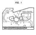
- a photosensitive drum 1 as a latent image bearing body is first rotated in the direction of arrow A, and is uniformly charged by a charging apparatus 2 for charging the photosensitive drum 1, and an electrostatic latent image is formed on the surface of the photosensitive drum 1 by a laser beam 3 which is exposing means for writing an electrostatic latent image on the photosensitive drum 1.
- the paper 13 to which the toner image has been transferred is subjected to the fixing process by a fixing apparatus 12, and is discharged out of the apparatus, and thus the printing operation is completed.
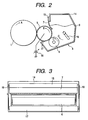
- the developing apparatus 4 according to the present embodiment will further be described with reference to Fig. 2.
- an elastic roller 6 abuts against the upstream side of the abutting portion of an elastic blade 7 against the surface of the developing roller 5 with respect to the direction of rotation of the developing roller 5 and is rotatably supported, in the developing container 14.
- foamed skeletal sponge structure or fur brush structure comprising fibers of rayon, nylon or the like implanted on a mandrel is preferable from the viewpoint of supplying the toner 8 to the developing roller 5 and scraping the undeveloped toner.
- the abutting width of this elastic roller 6 against the developing roller 5, 1 to 8 mm is effective, and it is preferable to give a relative speed to the developing roller 5 in the abutting portion, and in the present embodiment, the abutting width is set to 3 mm, and the elastic roller 6 is rotatively driven at predetermined timing by driving means (not shown) so that the peripheral speed of the elastic roller 6 may be 50 mm/s ( the relative speed to the developing roller 5 being 130 mm/s) during the developing operation.
- the elastic blade 7 On the downstream side of the elastic roller 6 with respect to the direction of rotation of the developing roller 5, the elastic blade 7 is supported by a blade supporting metal plate 15, and is provided so that the vicinity of the free end thereof may abut against the outer peripheral surface of the developing roller 5 in surface contact.
- the elastic blade 7 comprises a rubber material such as silicone or urethane, or a metal thin plate of SUS or phosphor bronze having spring elasticity as a base body and a rubber material adhered to the abutting surface thereof against the developing roller 5.
- the abutting direction of the elastic blade 7 against the developing roller 5 is the so-called counter direction in which, the tip end side thereof is positioned upstream of the abutting portion with respect to the direction of rotation of the developing roller 5.
- the elastic blade 7 is of a construction in which a urethane rubber plate having a thickness of 1.0 mm adhered to the blade supporting metal plate 15.
- Fig. 3 is a view of the developing apparatus 4 of Fig. 2 as it is seen from the direction of the photosensitive drum 1, and for the convenience of illustration, the developing roller 5 is not shown.
- end portion seal members 19 are provided in the opening portions of the developing container 14, and seal the space between the axially both end portions of the developing roller 5 and the opening portions of the developing container 14.
- the elastic blade 7, as shown in Fig. 3, is constructed so that the distance from the abutting nip thereof with the developing roller 5 indicated by hatching to the tip end of the elastic blade 7 may become continuously shorter from the ordinary developing area toward the opposite end portions of the elastic blade 7.
- the toner 8 is a non-magnetic monocomponent developer and as described above, use is made of a toner which is excellent in transferability and high in the lubricating property when the transfer residual toner not transferred but remaining on the photosensitive drum 1 is removed by cleaning means such as a blade or a fur brush and therefore has the advantage that the wear of the photo-sensitive drum 1 is small, i.e., a toner which is spherical and has a smooth surface.
- the volume resistance value of the toner is 10 14 ⁇ or greater, and as measuring conditions, a weight having a measuring electrode plate area of diameter of 6 mm ( ⁇ 6 mm) and 0.238 cm 2 , pressure of 1500 g is used to measure pressure of 980 gf/cm 2 (96.1 kPa), and the thickness of the powder layer during measurement 0.5 to 1.0 mm are set, and a DC voltage of 400 V is applied to measure the amount of current by a minute ammeter (YHP 4140 pA METER/DC VOLTAGE SOURCE), and the volume resistance value (specific resistance) is calculated from the resistance value.
- SF 1 is 100 to 180 and SF 2 is 100 to 140.
- the toner As a method of manufacturing the toner, it is possible to manufacture the toner by the use of a method of directly producing a toner by the use of a suspension polymerizing method described in Japanese Patent Application Laid-Open No. 36-10231 or Japanese Patent Application Laid-Open No.
- the shape factor SF 1 and SF 2 of the toner can be controlled easily to 100 to 180 and 100 to 140, respectively, and, by the use of the suspension polymerizing method under normal pressure or under pressure whereby there can be relatively easily obtained a fine particle toner having a shape particle size distribution and having a particle diameter of 4 to 8 ⁇ m, styrene and n-butyl acrylate as monomers a metal salicylate compound as a charge controlling agent, saturated polyester as polarity resin and further, a coloring agent were added to thereby manufacture colored suspension particles having a weight average particle diameter of 7 ⁇ m.
- the toner 8 is carried to the vicinity of the developing roller 5 by the elastic roller 6 being rotated in the direction of arrow D, and in the nip portion between the developing roller 5 and the elastic roller 6, the toner 8 carried on the elastic roller 6 frictionally contacts with the developing roller 5, whereby it is subjected to frictional charging and adheres onto the developing roller 5.
- the toner 8 adhering onto the developing roller 5 is sent under the pressure contact of the elastic blade 7 with the rotation of the developing roller 5 in the direction of arrow B, and a thin layer of the toner 8 is formed on the developing roller 5.
- -40 to -20 ⁇ C/g, 0.4 to 1.0 mg/cm 2 and 10 to 20 ⁇ m are set so as to be obtained as a good amount of charging, a good amount of toner coat and a toner layer thickness, respectively.
- the amount of charging of the toner is to be measured, the amount of charging of the toner after the toner on the developing roller 5 is subjected to the pressure contact by the elastic blade and before it comes to the opposed portion of the photosensitive drum 1 and the developing roller 5 is measured.
- That surface portion of the developing roller 5 which is exposed out of the developing container 14 is in contact with and opposed to the photosensitive drum 1 positioned at the left of the developing apparatus 4.
- the developing roller 5 is rotatively driven in the direction of arrow B, and the surface thereof has moderate unevenness for enhancing the probability of frictional contact with the toner 8 and effecting the carrying of the toner 8 well, and in the present embodiment, an elastic roller 6 coated with acryl-urethane resin on a silicone rubber layer having a diameter of 16 mm, a length of 216 mm and a thickness of 5 mm is used as the developing roller.
- the developing roller 5 is in pressure contact with the photosensitive drum 1 and is rotated at a peripheral speed of 80 mm/s somewhat higher than the peripheral speed of 50 mm of the photosensitive drum 1.
- the resistance R 1 ⁇ /mm of the developing roller will be defined here.
- a resistor of 10 k to 10 M ⁇ is disposed on the earth side, a DC voltage of 400 V is applied to the developing roller, the voltage across it is measured, the electric current thereof is calculated and the actually measured resistance value R 0 ⁇ is found.
- a value obtained by converting the resistance of the developing roller per 1 mm in the lengthwise direction (axial direction) thereof was then defined as the resistance R 1 ⁇ /mm of the developing roller.
- Each developing roller was installed in the developing device, as shown in Fig. 2, to thereby obtain a dither 64 gradation image.
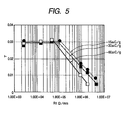
- the gradation curve of an image outputted at 1200 dpi dither 64 gradation is referred to as the ⁇ characteristic of developing, and the ⁇ characteristic when the amount of charging of the toner is -30.0 ⁇ C/g is shown in Fig. 4.
- the curves in Fig. 4 represent the gradation characteristics of images outputted by the developing rollers differing in resistance, and a straight line X is a straight line in which the ⁇ characteristic was subjected to primary recursion and the inclination thereof is 0.02, and this straight line X represents an ideal ⁇ characteristic.
- Fig. 5 shows the relation between the ⁇ values and the resistance of the developing roller when the amount of charging of the toner found in Fig. 4 is -30 ⁇ C/g and when it is -60.0 ⁇ C/g and -15.0 ⁇ C/g.
- the ⁇ value does not change when the resistance of the developing roller is 5 ⁇ 10 5 ⁇ /mm or less, but thereafter the ⁇ value and the resistance are proportional to each other.
- the toner layer formed as a thin layer on the developing roller 5 is uniformly carried to a developing portion which is the portion opposed to the photosensitive drum 1.
- the undeveloped toner which has not been consumed in the developing portion is collected from the lower portion of the developing roller 5 with the rotation of the developing roller 5.
- a seal member 17 comprising a flexible sheet is provided in this collecting portion, and permits the passage of the undeveloped toner into the developing container 14 and also prevents the toner 8 in the developing container 11 from leaking out from the lower portion of the developing roller 5.
- This collected undeveloped toner on the developing roller 5 is scraped from the surface of the developing roller 5 in the abutting portion of the elastic roller 6 and the developing roller 5.
- the present invention has been used as a process cartridge holding the developing apparatus therein and detachably attachable to the main body of the image forming apparatus
- the present invention may be used as a developing apparatus of such a construction that is fixed in the main body of the image forming apparatus and is supplied with only the toner, or may be used as a process cartridge holding the developing apparatus, the photosensitive drum, the cleaning blade, the waste toner containing container and the charging apparatus integrally therein and detachably attachable to the main body of the image forming apparatus.
- images of excellent gradation can be obtained in a contact monocomponent developing method of effecting development by bringing a developer layer carried on a developer carrying body into contact with a latent image bearing body.
Landscapes
- Physics & Mathematics (AREA)
- General Physics & Mathematics (AREA)
- Dry Development In Electrophotography (AREA)
Claims (12)
- Ein Entwicklungsgerät, umfassend:wobei, falls die Ladungsmenge pro 1 g des Entwicklers, nachdem die Schichtdicke durch das Schichtdicken-Regulierelement reguliert worden ist und bevor der Entwickler mit dem bildtragenden Körper in Kontakt gekommen ist, als Q (µC/g) definiert ist und falls der elektrische Widerstand pro 1 mm axialer Länge des Entwickler-Trägerkörpers als R (Ω/mm) definiert ist,einen Entwickler-Trägerkörper zur Trägerung eines Entwicklers darauf; undein Schichtdicken-Regulierelement zur Regulierung einer Schichtdicke des auf dem Entwickler-Trägerkörpers geträgerten Entwicklers, wobei der auf dem Entwickler-Trägerkörper geträgerte Entwickler mit einem bildtragenden Körper in Kontakt steht, nachdem dessen Schichtdicke durch das Schichtdicken-Regulierelement reguliert worden ist;
- Ein Entwicklungsgerät gemäß Anspruch 1, wobei der Entwickler ein nicht magnetischer Einkomponentenentwickler ist.
- Ein Entwicklungsgerät gemäß Anspruch 1, wobei der Entwickler-Trägerkörper eine elastische Walze mit Elastizität ist.
- Ein Entwicklungsgerät gemäß Anspruch 3, wobei die elastische Walze eine Silikonkautschukschicht und ein auf die Silikonkautschukschicht aufgeschichtetes Acryl-Urethan-Harz aufweist.
- Ein Entwicklungsgerät gemäß Anspruch 1, wobei das Schichtdicken-Regulierelement an den Entwicklungs-Trägerkörper anstößt.
- Ein Entwicklungsgerät gemäß Anspruch 5, wobei der Anstoßdruck 25 g/cm bis 35 g/cm beträgt.
- Ein Entwicklungsgerät gemäß Anspruch 2, wobei der Volumenwiderstandswert des Entwicklers bei 1014 Ω oder größer liegt.
- Ein Entwicklungsgerät gemäß Anspruch 2, wobei SF1 des Entwicklers bei 100 bis 180 und SF2 des Entwicklers bei 100 bis 140 liegen.
- Ein Entwicklungsgerät gemäß Anspruch 1, wobei die Ladungsmenge des Entwicklers bei -40 µC/g bis -20 µC/g liegt.
- Ein Entwicklungsgerät gemäß Anspruch 9, wobei die Entwicklermenge auf dem Entwickler-Trägerkörper nach der Regulierung der Schichtdicke durch das Schichtdicken-Regulierelement bei 0,4 mg/cm2 bis 1,0 mg/cm2 liegt.
- Ein Entwicklungsgerät gemäß Anspruch 9, wobei die Schichtdicke des Entwicklers auf dem Entwickler-Trägerkörper nach der Regulierung der Schichtdicke durch das Schichtdicken-Regulierelement bei 10 µm bis 20 µm liegt.
- Ein Entwicklungsgerät gemäß Anspruch 1, welches in einer Einheit mit dem bildtragenden Körper hergestellt ist, und an den Hauptkörper eines Bilderzeugungsgeräts als eine Verfahrenskartusche abnehmbar anbringbar ist.
Applications Claiming Priority (2)
| Application Number | Priority Date | Filing Date | Title |
|---|---|---|---|
| JP19875099 | 1999-07-13 | ||
| JP11198750A JP2001022176A (ja) | 1999-07-13 | 1999-07-13 | 現像装置及びこの現像装置を備えるプロセスカートリッジ並びに画像形成装置 |
Publications (3)
| Publication Number | Publication Date |
|---|---|
| EP1069483A2 EP1069483A2 (de) | 2001-01-17 |
| EP1069483A3 EP1069483A3 (de) | 2002-01-02 |
| EP1069483B1 true EP1069483B1 (de) | 2004-05-19 |
Family
ID=16396352
Family Applications (1)
| Application Number | Title | Priority Date | Filing Date |
|---|---|---|---|
| EP00115145A Expired - Lifetime EP1069483B1 (de) | 1999-07-13 | 2000-07-12 | Entwicklungsgerät |
Country Status (6)
| Country | Link |
|---|---|
| US (1) | US6308038B1 (de) |
| EP (1) | EP1069483B1 (de) |
| JP (1) | JP2001022176A (de) |
| KR (1) | KR100370531B1 (de) |
| CN (1) | CN1133904C (de) |
| DE (1) | DE60010809T2 (de) |
Families Citing this family (6)
| Publication number | Priority date | Publication date | Assignee | Title |
|---|---|---|---|---|
| US6806009B2 (en) * | 2001-12-21 | 2004-10-19 | Canon Kabushiki Kaisha | Electrophotographic photosensitive member, process cartridge and electrophotographic apparatus |
| JP4402391B2 (ja) * | 2003-07-17 | 2010-01-20 | キヤノン株式会社 | 現像装置 |
| US7013104B2 (en) | 2004-03-12 | 2006-03-14 | Lexmark International, Inc. | Toner regulating system having toner regulating member with metallic coating on flexible substrate |
| US7236729B2 (en) | 2004-07-27 | 2007-06-26 | Lexmark International, Inc. | Electrophotographic toner regulating member with induced strain outside elastic response region |
| JP4681869B2 (ja) * | 2004-12-16 | 2011-05-11 | キヤノン株式会社 | 現像装置、プロセスカートリッジ及び画像形成装置 |
| US7664442B2 (en) * | 2006-05-30 | 2010-02-16 | Canon Kabushiki Kaisha | Developing apparatus |
Family Cites Families (7)
| Publication number | Priority date | Publication date | Assignee | Title |
|---|---|---|---|---|
| JPS5953856A (ja) | 1982-09-21 | 1984-03-28 | Canon Inc | トナ−の製造方法 |
| GB2141643B (en) * | 1983-03-31 | 1986-10-22 | Konishiroku Photo Ind | Developing electrostatic latent images |
| JP2542373B2 (ja) * | 1986-02-19 | 1996-10-09 | 株式会社リコー | トナ−担持体 |
| JP2786722B2 (ja) * | 1990-07-10 | 1998-08-13 | 株式会社東芝 | 現像方法 |
| EP0713158B1 (de) * | 1994-11-17 | 2000-03-01 | Canon Kabushiki Kaisha | Bilderzeugungsgerät |
| US5867755A (en) * | 1995-12-05 | 1999-02-02 | Brother Kogyo Kabushiki Kaisha | Electrophotographic type image forming device and developing roller for use in the device |
| US5752146A (en) * | 1995-12-08 | 1998-05-12 | Brother Kogyo Kabushiki Kaisha | Electrophotographic type image forming device providing positive charge to toners |
-
1999
- 1999-07-13 JP JP11198750A patent/JP2001022176A/ja active Pending
-
2000
- 2000-07-11 US US09/614,384 patent/US6308038B1/en not_active Expired - Lifetime
- 2000-07-12 KR KR10-2000-0039773A patent/KR100370531B1/ko not_active Expired - Fee Related
- 2000-07-12 DE DE60010809T patent/DE60010809T2/de not_active Expired - Lifetime
- 2000-07-12 EP EP00115145A patent/EP1069483B1/de not_active Expired - Lifetime
- 2000-07-13 CN CNB001202162A patent/CN1133904C/zh not_active Expired - Fee Related
Also Published As
| Publication number | Publication date |
|---|---|
| DE60010809D1 (de) | 2004-06-24 |
| CN1133904C (zh) | 2004-01-07 |
| KR100370531B1 (ko) | 2003-01-30 |
| CN1280319A (zh) | 2001-01-17 |
| US6308038B1 (en) | 2001-10-23 |
| EP1069483A3 (de) | 2002-01-02 |
| DE60010809T2 (de) | 2005-06-23 |
| KR20010021067A (ko) | 2001-03-15 |
| JP2001022176A (ja) | 2001-01-26 |
| EP1069483A2 (de) | 2001-01-17 |
Similar Documents
| Publication | Publication Date | Title |
|---|---|---|
| US5311264A (en) | Developing apparatus for developing electrostatic latent image using one component developer | |
| US6195515B1 (en) | Developing apparatus including a seal member sandwiched between a developer bearing member and a leakage preventing member | |
| EP0908793B1 (de) | Entwicklungsvorrichtung | |
| US6594462B2 (en) | Developing apparatus using toner with conductive particles | |
| EP0387096B1 (de) | Bilderzeugungsverfahren | |
| US7058335B2 (en) | Process cartridge and image forming apparatus with toner fed cleaning mode | |
| US6470153B2 (en) | Developing device and developing method featuring a use-related control of a first voltage and a second voltage respectively, applied to a developer bearing member and a developer charging member | |
| US6337966B1 (en) | Developing device with developer charging device | |
| US6529699B2 (en) | Image forming apparatus and process cartridge detachably attachable to image forming apparatus comprising an image bearing body, and a developer carrying body | |
| EP1069483B1 (de) | Entwicklungsgerät | |
| US6594461B2 (en) | Charger and image formation apparatus using the charger | |
| US6542710B2 (en) | Developing apparatus for preventing developer from attaching to developer electrifying member | |
| JPH0764389A (ja) | 現像装置 | |
| JP2001337521A (ja) | 現像装置及び現像方法、並びに、画像形成装置 | |
| US6327451B1 (en) | Development device for use with an electrophotographic image-forming device | |
| JP3782560B2 (ja) | 現像装置、プロセスカートリッジおよび画像形成装置 | |
| JP4416296B2 (ja) | 画像形成装置 | |
| JPH08211741A (ja) | 画像形成装置及びプロセスカートリッジ | |
| JP2003057948A (ja) | 画像形成装置及びプロセスカートリッジ | |
| JP3782561B2 (ja) | 現像装置、プロセスカートリッジおよび画像形成装置 | |
| JP2000284589A (ja) | 現像装置、現像カートリッジ、プロセスカートリッジ及び画像形成装置 | |
| JPH05333676A (ja) | 現像装置 | |
| JP2002258612A (ja) | 現像装置、プロセスカートリッジ及び画像形成装置 | |
| JPH11305545A (ja) | 現像装置、プロセスカートリッジ及び画像形成装置 | |
| JP2003057949A (ja) | 現像装置、プロセスカートリッジ及び画像形成装置 |
Legal Events
| Date | Code | Title | Description |
|---|---|---|---|
| PUAI | Public reference made under article 153(3) epc to a published international application that has entered the european phase |
Free format text: ORIGINAL CODE: 0009012 |
|
| AK | Designated contracting states |
Kind code of ref document: A2 Designated state(s): AT BE CH CY DE DK ES FI FR GB GR IE IT LI LU MC NL PT SE Kind code of ref document: A2 Designated state(s): CH DE FR GB IT LI |
|
| AX | Request for extension of the european patent |
Free format text: AL;LT;LV;MK;RO;SI |
|
| PUAL | Search report despatched |
Free format text: ORIGINAL CODE: 0009013 |
|
| AK | Designated contracting states |
Kind code of ref document: A3 Designated state(s): AT BE CH CY DE DK ES FI FR GB GR IE IT LI LU MC NL PT SE |
|
| AX | Request for extension of the european patent |
Free format text: AL;LT;LV;MK;RO;SI |
|
| 17P | Request for examination filed |
Effective date: 20020514 |
|
| AKX | Designation fees paid |
Free format text: CH DE FR GB IT LI |
|
| GRAP | Despatch of communication of intention to grant a patent |
Free format text: ORIGINAL CODE: EPIDOSNIGR1 |
|
| GRAS | Grant fee paid |
Free format text: ORIGINAL CODE: EPIDOSNIGR3 |
|
| GRAA | (expected) grant |
Free format text: ORIGINAL CODE: 0009210 |
|
| AK | Designated contracting states |
Kind code of ref document: B1 Designated state(s): CH DE FR GB IT LI |
|
| REG | Reference to a national code |
Ref country code: GB Ref legal event code: FG4D |
|
| REG | Reference to a national code |
Ref country code: CH Ref legal event code: EP |
|
| REG | Reference to a national code |
Ref country code: IE Ref legal event code: FG4D |
|
| REF | Corresponds to: |
Ref document number: 60010809 Country of ref document: DE Date of ref document: 20040624 Kind code of ref document: P |
|
| REG | Reference to a national code |
Ref country code: CH Ref legal event code: NV Representative=s name: BOVARD AG PATENTANWAELTE |
|
| ET | Fr: translation filed | ||
| PLBE | No opposition filed within time limit |
Free format text: ORIGINAL CODE: 0009261 |
|
| STAA | Information on the status of an ep patent application or granted ep patent |
Free format text: STATUS: NO OPPOSITION FILED WITHIN TIME LIMIT |
|
| REG | Reference to a national code |
Ref country code: IE Ref legal event code: MM4A |
|
| 26N | No opposition filed |
Effective date: 20050222 |
|
| REG | Reference to a national code |
Ref country code: CH Ref legal event code: PFA Owner name: CANON KABUSHIKI KAISHA Free format text: CANON KABUSHIKI KAISHA#30-2, 3-CHOME, SHIMOMARUKO, OHTA-KU#TOKYO (JP) -TRANSFER TO- CANON KABUSHIKI KAISHA#30-2, 3-CHOME, SHIMOMARUKO, OHTA-KU#TOKYO (JP) |
|
| PGFP | Annual fee paid to national office [announced via postgrant information from national office to epo] |
Ref country code: CH Payment date: 20110718 Year of fee payment: 12 |
|
| PGFP | Annual fee paid to national office [announced via postgrant information from national office to epo] |
Ref country code: IT Payment date: 20120711 Year of fee payment: 13 Ref country code: FR Payment date: 20120808 Year of fee payment: 13 |
|
| REG | Reference to a national code |
Ref country code: CH Ref legal event code: PL |
|
| REG | Reference to a national code |
Ref country code: FR Ref legal event code: ST Effective date: 20140331 |
|
| PG25 | Lapsed in a contracting state [announced via postgrant information from national office to epo] |
Ref country code: LI Free format text: LAPSE BECAUSE OF NON-PAYMENT OF DUE FEES Effective date: 20130731 Ref country code: CH Free format text: LAPSE BECAUSE OF NON-PAYMENT OF DUE FEES Effective date: 20130731 |
|
| PG25 | Lapsed in a contracting state [announced via postgrant information from national office to epo] |
Ref country code: FR Free format text: LAPSE BECAUSE OF NON-PAYMENT OF DUE FEES Effective date: 20130731 Ref country code: IT Free format text: LAPSE BECAUSE OF NON-PAYMENT OF DUE FEES Effective date: 20130712 |
|
| PGFP | Annual fee paid to national office [announced via postgrant information from national office to epo] |
Ref country code: GB Payment date: 20150727 Year of fee payment: 16 Ref country code: DE Payment date: 20150731 Year of fee payment: 16 |
|
| REG | Reference to a national code |
Ref country code: DE Ref legal event code: R119 Ref document number: 60010809 Country of ref document: DE |
|
| GBPC | Gb: european patent ceased through non-payment of renewal fee |
Effective date: 20160712 |
|
| PG25 | Lapsed in a contracting state [announced via postgrant information from national office to epo] |
Ref country code: DE Free format text: LAPSE BECAUSE OF NON-PAYMENT OF DUE FEES Effective date: 20170201 |
|
| PG25 | Lapsed in a contracting state [announced via postgrant information from national office to epo] |
Ref country code: GB Free format text: LAPSE BECAUSE OF NON-PAYMENT OF DUE FEES Effective date: 20160712 |