EP1069483A2 - Appareil de développement - Google Patents
Appareil de développement Download PDFInfo
- Publication number
- EP1069483A2 EP1069483A2 EP00115145A EP00115145A EP1069483A2 EP 1069483 A2 EP1069483 A2 EP 1069483A2 EP 00115145 A EP00115145 A EP 00115145A EP 00115145 A EP00115145 A EP 00115145A EP 1069483 A2 EP1069483 A2 EP 1069483A2
- Authority
- EP
- European Patent Office
- Prior art keywords
- developer
- layer thickness
- developing apparatus
- developing
- toner
- Prior art date
- Legal status (The legal status is an assumption and is not a legal conclusion. Google has not performed a legal analysis and makes no representation as to the accuracy of the status listed.)
- Granted
Links
Images


Classifications
-
- G—PHYSICS
- G03—PHOTOGRAPHY; CINEMATOGRAPHY; ANALOGOUS TECHNIQUES USING WAVES OTHER THAN OPTICAL WAVES; ELECTROGRAPHY; HOLOGRAPHY
- G03G—ELECTROGRAPHY; ELECTROPHOTOGRAPHY; MAGNETOGRAPHY
- G03G15/00—Apparatus for electrographic processes using a charge pattern
- G03G15/06—Apparatus for electrographic processes using a charge pattern for developing
- G03G15/08—Apparatus for electrographic processes using a charge pattern for developing using a solid developer, e.g. powder developer
- G03G15/0806—Apparatus for electrographic processes using a charge pattern for developing using a solid developer, e.g. powder developer on a donor element, e.g. belt, roller
- G03G15/0818—Apparatus for electrographic processes using a charge pattern for developing using a solid developer, e.g. powder developer on a donor element, e.g. belt, roller characterised by the structure of the donor member, e.g. surface properties
-
- G—PHYSICS
- G03—PHOTOGRAPHY; CINEMATOGRAPHY; ANALOGOUS TECHNIQUES USING WAVES OTHER THAN OPTICAL WAVES; ELECTROGRAPHY; HOLOGRAPHY
- G03G—ELECTROGRAPHY; ELECTROPHOTOGRAPHY; MAGNETOGRAPHY
- G03G2215/00—Apparatus for electrophotographic processes
- G03G2215/08—Details of powder developing device not concerning the development directly
- G03G2215/0855—Materials and manufacturing of the developing device
- G03G2215/0858—Donor member
- G03G2215/0861—Particular composition or materials
Definitions
- This invention relates to a developing apparatus provided in an image forming apparatus such as a copier of the electro-photographic type or a printer.
- an image forming apparatus in which an electrical latent image is formed on a photosensitive body which is a latent image bearing body utilizing a photoconductive substance by one of various method, and then the latent image is developed by a developing apparatus with a toner which is a developer and is visualized as a toner image, and as required, the toner image is transferred to a transferring material which is a recording medium such as paper, whereafter heat and pressure or the like are imparted to the toner image to thereby fix the toner image and obtain a copy.
- a transferring material which is a recording medium such as paper
- developing is effected with the developing roller abutting against or brought into pressure contact with the photosensitive body bearing the electrostatic latent image thereon and therefore, it is necessary to use a developing roller having elasticity.
- the developing roller when the developing roller is to be brought into contact with a latent image bearing body comprising a rigid body, it becomes a requisite condition to use a developing roller having elasticity in order to avoid injuring the latent image bearing body.
- an electrically conductive developing roller When an electrically conductive developing roller is used, an electric current is created in the nip portion between the photosensitive body and the developing roller by the movement of the toner having charges, and developing is effected even at a low developing potential difference (the difference between the surface potential of the electrostatic latent image bearing body and the developing bias potential) and high image density is obtained.
- Fig. 1 is a cross-sectional view schematically showing the construction of an image forming apparatus according to the present embodiment
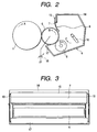
- Fig. 2 is a cross-sectional view schematically showing the construction of a developing apparatus provided in the image forming apparatus of Fig. 1.
- a photosensitive drum 1 as a latent image bearing body is first rotated in the direction of arrow A, and is uniformly charged by a charging apparatus 2 for charging the photosensitive drum 1, and an electrostatic latent image is formed on the surface of the photosensitive drum 1 by a laser beam 3 which is exposing means for writing an electrostatic latent image on the photosensitive drum 1.
- the electrostatic latent image is developed by a toner which is a developer being imparted thereto by a developing apparatus held in a process cartridge (not shown) disposed in proximity to the photosensitive drum 1 and detachably attachable to the main body of the image forming apparatus, and is visualized as a toner image.
- a toner which is a developer being imparted thereto by a developing apparatus held in a process cartridge (not shown) disposed in proximity to the photosensitive drum 1 and detachably attachable to the main body of the image forming apparatus, and is visualized as a toner image.
- the so-called reversal developing for forming a toner image in an exposing portion is effected.
- the visualized toner image on the photosensitive drum 1 is transferred to paper 13 which is a recording medium by a transferring roller 9.
- the paper 13 to which the toner image has been transferred is subjected to the fixing process by a fixing apparatus 12, and is discharged out of the apparatus, and thus the printing operation is completed.
- the transfer residual toner not transferred but remaining on the photosensitive drum 1 is scraped off by a cleaning blade 10 and is contained in a waste toner container 11, and the cleaned photosensitive drum 1 repetitively effects the above-described action.
- the developing apparatus 4 according to the present embodiment will further be described with reference to Fig. 2.
- the developing apparatus 4 as shown in Fig. 4, is provided with a developing container 14 containing therein a non-magnetic toner 8 as a monocomponent developer, and a developing roller 5 as a developer carrying body positioned in an opening portion extending in the lengthwise direction in the developing container 14 and disposed in opposed relationship with the photosensitive drum 1, and is adapted to develop and visualize the electrostatic latent image on the photosensitive drum 1.
- a developing container 14 containing therein a non-magnetic toner 8 as a monocomponent developer
- a developing roller 5 as a developer carrying body positioned in an opening portion extending in the lengthwise direction in the developing container 14 and disposed in opposed relationship with the photosensitive drum 1, and is adapted to develop and visualize the electrostatic latent image on the photosensitive drum 1.
- a toner layer carried on the developing roller 5 is in contact with the photosensitive drum 1 with an abutting width.
- an elastic roller 6 abuts against the upstream side of the abutting portion of an elastic blade 7 against the surface of the developing roller 5 with respect to the direction of rotation of the developing roller 5 and is rotatably supported, in the developing container 14.
- foamed skeletal sponge structure or fur brush structure comprising fibers of rayon, nylon or the like implanted on a mandrel is preferable from the viewpoint of supplying the toner 8 to the developing roller 5 and scraping the undeveloped toner.
- the abutting width of this elastic roller 6 against the developing roller 5, 1 to 8 mm is effective, and it is preferable to give a relative speed to the developing roller 5 in the abutting portion, and in the present embodiment, the abutting width is set to 3 mm, and the elastic roller 6 is rotatively driven at predetermined timing by driving means (not shown) so that the peripheral speed of the elastic roller 6 may be 50 mm/s ( the relative speed to the developing roller 5 being 130 mm/s) during the developing operation.
- the elastic blade 7 On the downstream side of the elastic roller 6 with respect to the direction of rotation of the developing roller 5, the elastic blade 7 is supported by a blade supporting metal plate 15, and is provided so that the vicinity of the free end thereof may abut against the outer peripheral surface of the developing roller 5 in surface contact.
- the elastic blade 7 comprises a rubber material such as silicone or urethane, or a metal thin plate of SUS or phosphor bronze having spring elasticity as a base body and a rubber material adhered to the abutting surface thereof against the developing roller 5.
- the abutting direction of the elastic blade 7 against the developing roller 5 is the so-called counter direction in which, the tip end side thereof is positioned upstream of the abutting portion with respect to the direction of rotation of the developing roller 5.
- the elastic blade 7 is of a construction in which a urethane rubber plate having a thickness of 1.0 mm adhered to the blade supporting metal plate 15.
- the abutting pressure of the elastic blade 7 against the developing roller 5 was set to 25 to 35 g/cm (the measurement of line pressure is effected by converting from a value at which three metal thin plats of a known coefficient of friction were inserted into the abutting portion and the central one of them was drawn out by a spring balance).
- Fig. 3 is a view of the developing apparatus 4 of Fig. 2 as it is seen from the direction of the photosensitive drum 1, and for the convenience of illustration, the developing roller 5 is not shown.
- end portion seal members 19 are provided in the opening portions of the developing container 14, and seal the space between the axially both end portions of the developing roller 5 and the opening portions of the developing container 14.
- the elastic blade 7, as shown in Fig. 3, is constructed so that the distance from the abutting nip thereof with the developing roller 5 indicated by hatching to the tip end of the elastic blade 7 may become continuously shorter from the ordinary developing area toward the opposite end portions of the elastic blade 7.
- the blade tip end position at the both end portions of the elastic blade 7 in the axial direction of the developing roller 5 is designed to be within the above-mentioned abutting nip.
- the thickness of the toner layer formed on the developing roller 5 is affected by the distance from an upstream point of the abutting nip with respect to the direction of rotation of the developing roller 5 to the tip end thereof, and as is heretofore known, the longer becomes this distance, the thicker becomes the toner layer formed on the developing roller 5, and the shorter becomes this distance, the thinner becomes the toner layer.
- the toner 8 is a non-magnetic monocomponent developer and as described above, use is made of a toner which is excellent in transferability and high in the lubricating property when the transfer residual toner not transferred but remaining on the photosensitive drum 1 is removed by cleaning means such as a blade or a fur brush and therefore has the advantage that the wear of the photo-sensitive drum 1 is small, i.e., a toner which is spherical and has a smooth surface.
- the volume resistance value of the toner is 10 14 ⁇ or greater, and as measuring conditions, a weight having a measuring electrode plate area of diameter of 6 mm ( ⁇ 6 mm) and 0.238 cm 2 , pressure of 1500 g is used to measure pressure of 980 gf/cm 2 (96.1 kPa), and the thickness of the powder layer during measurement 0.5 to 1.0 mm are set, and a DC voltage of 400 V is applied to measure the amount of current by a minute ammeter (YHP 4140 pA METER/DC VOLTAGE SOURCE), and the volume resistance value (specific resistance) is calculated from the resistance value.
- SF 1 is 100 to 180 and SF 2 is 100 to 140.
- SF 1 and SF 2 values obtained by sampling 100 toner images at random by the use of FE-SEM (S-800) produced by Hitachi, Ltd., introducing the image information thereof into an image analyzing apparatus (Luzex 3) produced by Nicolet Japan Corporation through an interface and effecting analysis, and calculating from the following expressions are defined.
- SF 1 ⁇ (MXLNG) 2 /AREA ⁇ ⁇ ( ⁇ /4) ⁇
- SF 2 ⁇ (PERI) 2 /AREA ⁇ ⁇ (1/4 ⁇ ) ⁇ 100
- the shape factor SF 1 of this toner indicates the degree of sphericity, and as it becomes greater from 100, the shape gradually becomes from sphericity to an amorphous shape, and SF 2 indicates the degree of unevenness, and as it becomes greater from 100, the unevenness of the surface of the toner becomes remarkable.
- the toner As a method of manufacturing the toner, it is possible to manufacture the toner by the use of a method of directly producing a toner by the use of a suspension polymerizing method described in Japanese Patent Application Laid-Open No. 36-10231 or Japanese Patent Application Laid-Open No.
- a dispersion polymerizing method of directly producing a toner by the use of a water organic solvent soluble in a monomer but in which an obtained polymer is insoluble or an emulsion polymerizing method typified by a soap-free polymerizing method of producing a toner by directly polymerizing under the presence of a water soluble polarity polymerization starting agent, besides a manufacturing method using the so-called crushing method, if within the range of the above-described shape factors.
- the shape factor SF 1 and SF 2 of the toner can be controlled easily to 100 to 180 and 100 to 140, respectively, and, by the use of the suspension polymerizing method under normal pressure or under pressure whereby there can be relatively easily obtained a fine particle toner having a shape particle size distribution and having a particle diameter of 4 to 8 ⁇ m, styrene and n-butyl acrylate as monomers a metal salicylate compound as a charge controlling agent, saturated polyester as polarity resin and further, a coloring agent were added to thereby manufacture colored suspension particles having a weight average particle diameter of 7 ⁇ m.
- Hydrophobic silica was extraneously added thereto by 1.5 wt%, whereby there was manufactured the toner 8 of the negative polarity which was excellent in transferability and by which the wear of the photosensitive drum 1 during the cleaning thereof was small, as described above.
- the toner 8 in the developing container 14 is sent toward the elastic roller 6 with the rotation of an agitating member 16 in the direction of arrow C.
- the toner 8 is carried to the vicinity of the developing roller 5 by the elastic roller 6 being rotated in the direction of arrow D, and in the nip portion between the developing roller 5 and the elastic roller 6, the toner 8 carried on the elastic roller 6 frictionally contacts with the developing roller 5, whereby it is subjected to frictional charging and adheres onto the developing roller 5.
- the toner 8 adhering onto the developing roller 5 is sent under the pressure contact of the elastic blade 7 with the rotation of the developing roller 5 in the direction of arrow B, and a thin layer of the toner 8 is formed on the developing roller 5.
- -40 to -20 ⁇ C/g, 0.4 to 1.0 mg/cm 2 and 10 to 20 ⁇ m are set so as to be obtained as a good amount of charging, a good amount of toner coat and a toner layer thickness, respectively.
- the amount of charging of the toner is to be measured, the amount of charging of the toner after the toner on the developing roller 5 is subjected to the pressure contact by the elastic blade and before it comes to the opposed portion of the photosensitive drum 1 and the developing roller 5 is measured.
- the developing roller 5 has its right substantially half peripheral surface plunged into the developing container 14 in the above-described opening portion, and has its left substantially half peripheral surface exposed out of the developing container 14.
- That surface portion of the developing roller 5 which is exposed out of the developing container 14 is in contact with and opposed to the photosensitive drum 1 positioned at the left of the developing apparatus 4.
- the developing roller 5 is rotatively driven in the direction of arrow B, and the surface thereof has moderate unevenness for enhancing the probability of frictional contact with the toner 8 and effecting the carrying of the toner 8 well, and in the present embodiment, an elastic roller 6 coated with acrylurethane resin on a silicone rubber layer having a diameter of 16 mm, a length of 216 mm and a thickness of 5 mm is used as the developing roller.
- the developing roller 5 is in pressure contact with the photosensitive drum 1 and is rotated at a peripheral speed of 80 mm/s somewhat higher than the peripheral speed of 50 mm of the photosensitive drum 1.
- the resistance R 1 ⁇ /mm of the developing roller will be defined here.
- a resistor of 10 k to 10 M ⁇ is disposed on the earth side, a DC voltage of 400 V is applied to the developing roller, the voltage across it is measured, the electric current thereof is calculated and the actually measured resistance value R 0 ⁇ is found.
- a value obtained by converting the resistance of the developing roller per 1 mm in the lengthwise direction (axial direction) thereof was then defined as the resistance R 1 ⁇ /mm of the developing roller.
- Each developing roller was installed in the developing device, as shown in Fig. 2, to thereby obtain a dither 64 gradation image.
- the developing conditions were as follows. Surface potential of the unexposed portion of the photosensitive body: -600 V Developing bias potential: -300 V Toner charging amount: -60.0 ⁇ C/g, -30.0 ⁇ C/g, -15.0 ⁇ C/g Amount of toner adhering onto the developing roller: 0.4 mg/cm 2 Resistance R 1 of the developing roller: 2.55 ⁇ 10 3 ⁇ /mm, 1.50 ⁇ 10 4 ⁇ /mm, 4.63 ⁇ 10 4 ⁇ /mm, 1.00 ⁇ 10 5 ⁇ /mm, 9.26 ⁇ 10 5 ⁇ /mm, 1.85 ⁇ 10 6 ⁇ /mm, 4.63 ⁇ 10 6 ⁇ /mm
- the gradation curve of an image outputted at 1200 dpi dither 64 gradation is referred to as the ⁇ characteristic of developing, and the ⁇ characteristic when the amount of charging of the toner is -30.0 ⁇ C/g is shown in Fig. 4.
- the curves in Fig. 4 represent the gradation characteristics of images outputted by the developing rollers differing in resistance, and a straight line X is a straight line in which the ⁇ characteristic was subjected to primary recursion and the inclination thereof is 0.02, and this straight line X represents an ideal ⁇ characteristic.
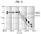
- Fig. 5 shows the relation between the ⁇ values and the resistance of the developing roller when the amount of charging of the toner found in Fig. 4 is -30 ⁇ C/g and when it is -60.0 ⁇ C/g and -15.0 ⁇ C/g.
- the ⁇ value does not change when the resistance of the developing roller is 5 ⁇ 10 5 ⁇ /mm or less, but thereafter the ⁇ value and the resistance are proportional to each other.
- the toner layer formed as a thin layer on the developing roller 5 is uniformly carried to a developing portion which is the portion opposed to the photosensitive drum 1.
- the toner layer formed as a thin layer on the developing roller 5 develops the electrostatic latent image on the photosensitive drum 1 as a toner image by the DC voltage of the developing roller 5.
- the undeveloped toner which has not been consumed in the developing portion is collected from the lower portion of the developing roller 5 with the rotation of the developing roller 5.
- a seal member 17 comprising a flexible sheet is provided in this collecting portion, and permits the passage of the undeveloped toner into the developing container 14 and also prevents the toner 8 in the developing container 11 from leaking out from the lower portion of the developing roller 5.
- This collected undeveloped toner on the developing roller 5 is scraped from the surface of the developing roller 5 in the abutting portion of the elastic roller 6 and the developing roller 5.
- the present invention has been used as a process cartridge holding the developing apparatus therein and detachably attachable to the main body of the image forming apparatus
- the present invention may be used as a developing apparatus of such a construction that is fixed in the main body of the image forming apparatus and is supplied with only the toner, or may be used as a process cartridge holding the developing apparatus, the photosensitive drum, the cleaning blade, the waste toner containing container and the charging apparatus integrally therein and detachably attachable to the main body of the image forming apparatus.
- images of excellent gradation can be obtained in a contact monocomponent developing method of effecting development by bringing a developer layer carried on a developer carrying body into contact with a latent image bearing body.
- the present invention provides a developing apparatus which has a developer carrying body carrying a developer thereon, and a layer thickness regulating member for regulating the layer thickness of the developer carried on the developer carrying body, the developer carried on the developer carrying body contacting with an image bearing body after the layer thickness thereof has been regulated by the layer thickness regulating member.
- the charge amount per 1 g of the developer after the layer thickness has been regulated by the layer thickness regulating member and before the developer contacts with the image bearing body is defined as Q ( ⁇ C/g) and the electrical resistance per axial length 1 mm of the developer carrying body is defined as R ( ⁇ /mm)
- Q ( ⁇ C/g) and the electrical resistance per axial length 1 mm of the developer carrying body is defined as R ( ⁇ /mm)
- + 7.05 ⁇ 10 6 ) are satisfied.
Landscapes
- Physics & Mathematics (AREA)
- General Physics & Mathematics (AREA)
- Dry Development In Electrophotography (AREA)
Applications Claiming Priority (2)
| Application Number | Priority Date | Filing Date | Title |
|---|---|---|---|
| JP19875099 | 1999-07-13 | ||
| JP11198750A JP2001022176A (ja) | 1999-07-13 | 1999-07-13 | 現像装置及びこの現像装置を備えるプロセスカートリッジ並びに画像形成装置 |
Publications (3)
| Publication Number | Publication Date |
|---|---|
| EP1069483A2 true EP1069483A2 (fr) | 2001-01-17 |
| EP1069483A3 EP1069483A3 (fr) | 2002-01-02 |
| EP1069483B1 EP1069483B1 (fr) | 2004-05-19 |
Family
ID=16396352
Family Applications (1)
| Application Number | Title | Priority Date | Filing Date |
|---|---|---|---|
| EP00115145A Expired - Lifetime EP1069483B1 (fr) | 1999-07-13 | 2000-07-12 | Appareil de développement |
Country Status (6)
| Country | Link |
|---|---|
| US (1) | US6308038B1 (fr) |
| EP (1) | EP1069483B1 (fr) |
| JP (1) | JP2001022176A (fr) |
| KR (1) | KR100370531B1 (fr) |
| CN (1) | CN1133904C (fr) |
| DE (1) | DE60010809T2 (fr) |
Families Citing this family (6)
| Publication number | Priority date | Publication date | Assignee | Title |
|---|---|---|---|---|
| US6806009B2 (en) * | 2001-12-21 | 2004-10-19 | Canon Kabushiki Kaisha | Electrophotographic photosensitive member, process cartridge and electrophotographic apparatus |
| JP4402391B2 (ja) * | 2003-07-17 | 2010-01-20 | キヤノン株式会社 | 現像装置 |
| US7013104B2 (en) | 2004-03-12 | 2006-03-14 | Lexmark International, Inc. | Toner regulating system having toner regulating member with metallic coating on flexible substrate |
| US7236729B2 (en) | 2004-07-27 | 2007-06-26 | Lexmark International, Inc. | Electrophotographic toner regulating member with induced strain outside elastic response region |
| JP4681869B2 (ja) * | 2004-12-16 | 2011-05-11 | キヤノン株式会社 | 現像装置、プロセスカートリッジ及び画像形成装置 |
| US7664442B2 (en) * | 2006-05-30 | 2010-02-16 | Canon Kabushiki Kaisha | Developing apparatus |
Family Cites Families (7)
| Publication number | Priority date | Publication date | Assignee | Title |
|---|---|---|---|---|
| JPS5953856A (ja) | 1982-09-21 | 1984-03-28 | Canon Inc | トナ−の製造方法 |
| GB2141643B (en) * | 1983-03-31 | 1986-10-22 | Konishiroku Photo Ind | Developing electrostatic latent images |
| JP2542373B2 (ja) * | 1986-02-19 | 1996-10-09 | 株式会社リコー | トナ−担持体 |
| JP2786722B2 (ja) * | 1990-07-10 | 1998-08-13 | 株式会社東芝 | 現像方法 |
| EP0713158B1 (fr) * | 1994-11-17 | 2000-03-01 | Canon Kabushiki Kaisha | Appareil de formation d'images |
| US5867755A (en) * | 1995-12-05 | 1999-02-02 | Brother Kogyo Kabushiki Kaisha | Electrophotographic type image forming device and developing roller for use in the device |
| US5752146A (en) * | 1995-12-08 | 1998-05-12 | Brother Kogyo Kabushiki Kaisha | Electrophotographic type image forming device providing positive charge to toners |
-
1999
- 1999-07-13 JP JP11198750A patent/JP2001022176A/ja active Pending
-
2000
- 2000-07-11 US US09/614,384 patent/US6308038B1/en not_active Expired - Lifetime
- 2000-07-12 KR KR10-2000-0039773A patent/KR100370531B1/ko not_active Expired - Fee Related
- 2000-07-12 DE DE60010809T patent/DE60010809T2/de not_active Expired - Lifetime
- 2000-07-12 EP EP00115145A patent/EP1069483B1/fr not_active Expired - Lifetime
- 2000-07-13 CN CNB001202162A patent/CN1133904C/zh not_active Expired - Fee Related
Also Published As
| Publication number | Publication date |
|---|---|
| DE60010809D1 (de) | 2004-06-24 |
| CN1133904C (zh) | 2004-01-07 |
| KR100370531B1 (ko) | 2003-01-30 |
| CN1280319A (zh) | 2001-01-17 |
| US6308038B1 (en) | 2001-10-23 |
| EP1069483A3 (fr) | 2002-01-02 |
| DE60010809T2 (de) | 2005-06-23 |
| KR20010021067A (ko) | 2001-03-15 |
| EP1069483B1 (fr) | 2004-05-19 |
| JP2001022176A (ja) | 2001-01-26 |
Similar Documents
| Publication | Publication Date | Title |
|---|---|---|
| US5311264A (en) | Developing apparatus for developing electrostatic latent image using one component developer | |
| US6195515B1 (en) | Developing apparatus including a seal member sandwiched between a developer bearing member and a leakage preventing member | |
| EP0908793B1 (fr) | Dispositif de développement | |
| US6594462B2 (en) | Developing apparatus using toner with conductive particles | |
| EP1033630A2 (fr) | Appareil de développement et appareil de formation d'images | |
| US7058335B2 (en) | Process cartridge and image forming apparatus with toner fed cleaning mode | |
| US6470153B2 (en) | Developing device and developing method featuring a use-related control of a first voltage and a second voltage respectively, applied to a developer bearing member and a developer charging member | |
| US6337966B1 (en) | Developing device with developer charging device | |
| US6529699B2 (en) | Image forming apparatus and process cartridge detachably attachable to image forming apparatus comprising an image bearing body, and a developer carrying body | |
| EP1069483B1 (fr) | Appareil de développement | |
| US6594461B2 (en) | Charger and image formation apparatus using the charger | |
| US6542710B2 (en) | Developing apparatus for preventing developer from attaching to developer electrifying member | |
| JPH0764389A (ja) | 現像装置 | |
| CA2105254C (fr) | Dispositif de developpement pour appareil electrophotographique | |
| US6389253B1 (en) | Image forming apparatus featuring a regulating member for regulating a number of layers of a developer carried by a developer carrying member | |
| JP3782560B2 (ja) | 現像装置、プロセスカートリッジおよび画像形成装置 | |
| JP4416296B2 (ja) | 画像形成装置 | |
| JP2003057948A (ja) | 画像形成装置及びプロセスカートリッジ | |
| JP3782561B2 (ja) | 現像装置、プロセスカートリッジおよび画像形成装置 | |
| JPH05333676A (ja) | 現像装置 | |
| JPH11305545A (ja) | 現像装置、プロセスカートリッジ及び画像形成装置 | |
| JP2000227713A (ja) | 現像装置 | |
| JP2002258612A (ja) | 現像装置、プロセスカートリッジ及び画像形成装置 | |
| JP2000155465A (ja) | 現像装置 | |
| JP2003057949A (ja) | 現像装置、プロセスカートリッジ及び画像形成装置 |
Legal Events
| Date | Code | Title | Description |
|---|---|---|---|
| PUAI | Public reference made under article 153(3) epc to a published international application that has entered the european phase |
Free format text: ORIGINAL CODE: 0009012 |
|
| AK | Designated contracting states |
Kind code of ref document: A2 Designated state(s): AT BE CH CY DE DK ES FI FR GB GR IE IT LI LU MC NL PT SE Kind code of ref document: A2 Designated state(s): CH DE FR GB IT LI |
|
| AX | Request for extension of the european patent |
Free format text: AL;LT;LV;MK;RO;SI |
|
| PUAL | Search report despatched |
Free format text: ORIGINAL CODE: 0009013 |
|
| AK | Designated contracting states |
Kind code of ref document: A3 Designated state(s): AT BE CH CY DE DK ES FI FR GB GR IE IT LI LU MC NL PT SE |
|
| AX | Request for extension of the european patent |
Free format text: AL;LT;LV;MK;RO;SI |
|
| 17P | Request for examination filed |
Effective date: 20020514 |
|
| AKX | Designation fees paid |
Free format text: CH DE FR GB IT LI |
|
| GRAP | Despatch of communication of intention to grant a patent |
Free format text: ORIGINAL CODE: EPIDOSNIGR1 |
|
| GRAS | Grant fee paid |
Free format text: ORIGINAL CODE: EPIDOSNIGR3 |
|
| GRAA | (expected) grant |
Free format text: ORIGINAL CODE: 0009210 |
|
| AK | Designated contracting states |
Kind code of ref document: B1 Designated state(s): CH DE FR GB IT LI |
|
| REG | Reference to a national code |
Ref country code: GB Ref legal event code: FG4D |
|
| REG | Reference to a national code |
Ref country code: CH Ref legal event code: EP |
|
| REG | Reference to a national code |
Ref country code: IE Ref legal event code: FG4D |
|
| REF | Corresponds to: |
Ref document number: 60010809 Country of ref document: DE Date of ref document: 20040624 Kind code of ref document: P |
|
| REG | Reference to a national code |
Ref country code: CH Ref legal event code: NV Representative=s name: BOVARD AG PATENTANWAELTE |
|
| ET | Fr: translation filed | ||
| PLBE | No opposition filed within time limit |
Free format text: ORIGINAL CODE: 0009261 |
|
| STAA | Information on the status of an ep patent application or granted ep patent |
Free format text: STATUS: NO OPPOSITION FILED WITHIN TIME LIMIT |
|
| REG | Reference to a national code |
Ref country code: IE Ref legal event code: MM4A |
|
| 26N | No opposition filed |
Effective date: 20050222 |
|
| REG | Reference to a national code |
Ref country code: CH Ref legal event code: PFA Owner name: CANON KABUSHIKI KAISHA Free format text: CANON KABUSHIKI KAISHA#30-2, 3-CHOME, SHIMOMARUKO, OHTA-KU#TOKYO (JP) -TRANSFER TO- CANON KABUSHIKI KAISHA#30-2, 3-CHOME, SHIMOMARUKO, OHTA-KU#TOKYO (JP) |
|
| PGFP | Annual fee paid to national office [announced via postgrant information from national office to epo] |
Ref country code: CH Payment date: 20110718 Year of fee payment: 12 |
|
| PGFP | Annual fee paid to national office [announced via postgrant information from national office to epo] |
Ref country code: IT Payment date: 20120711 Year of fee payment: 13 Ref country code: FR Payment date: 20120808 Year of fee payment: 13 |
|
| REG | Reference to a national code |
Ref country code: CH Ref legal event code: PL |
|
| REG | Reference to a national code |
Ref country code: FR Ref legal event code: ST Effective date: 20140331 |
|
| PG25 | Lapsed in a contracting state [announced via postgrant information from national office to epo] |
Ref country code: LI Free format text: LAPSE BECAUSE OF NON-PAYMENT OF DUE FEES Effective date: 20130731 Ref country code: CH Free format text: LAPSE BECAUSE OF NON-PAYMENT OF DUE FEES Effective date: 20130731 |
|
| PG25 | Lapsed in a contracting state [announced via postgrant information from national office to epo] |
Ref country code: FR Free format text: LAPSE BECAUSE OF NON-PAYMENT OF DUE FEES Effective date: 20130731 Ref country code: IT Free format text: LAPSE BECAUSE OF NON-PAYMENT OF DUE FEES Effective date: 20130712 |
|
| PGFP | Annual fee paid to national office [announced via postgrant information from national office to epo] |
Ref country code: GB Payment date: 20150727 Year of fee payment: 16 Ref country code: DE Payment date: 20150731 Year of fee payment: 16 |
|
| REG | Reference to a national code |
Ref country code: DE Ref legal event code: R119 Ref document number: 60010809 Country of ref document: DE |
|
| GBPC | Gb: european patent ceased through non-payment of renewal fee |
Effective date: 20160712 |
|
| PG25 | Lapsed in a contracting state [announced via postgrant information from national office to epo] |
Ref country code: DE Free format text: LAPSE BECAUSE OF NON-PAYMENT OF DUE FEES Effective date: 20170201 |
|
| PG25 | Lapsed in a contracting state [announced via postgrant information from national office to epo] |
Ref country code: GB Free format text: LAPSE BECAUSE OF NON-PAYMENT OF DUE FEES Effective date: 20160712 |