EP1069412B1 - Appareil de pesage pour peser des objets sur des véhicules - Google Patents
Appareil de pesage pour peser des objets sur des véhicules Download PDFInfo
- Publication number
- EP1069412B1 EP1069412B1 EP20000114642 EP00114642A EP1069412B1 EP 1069412 B1 EP1069412 B1 EP 1069412B1 EP 20000114642 EP20000114642 EP 20000114642 EP 00114642 A EP00114642 A EP 00114642A EP 1069412 B1 EP1069412 B1 EP 1069412B1
- Authority
- EP
- European Patent Office
- Prior art keywords
- force
- parts
- weighing device
- disposed
- vehicle
- Prior art date
- Legal status (The legal status is an assumption and is not a legal conclusion. Google has not performed a legal analysis and makes no representation as to the accuracy of the status listed.)
- Expired - Lifetime
Links
- 238000005303 weighing Methods 0.000 title claims description 37
- 238000006073 displacement reaction Methods 0.000 claims description 6
- 239000002184 metal Substances 0.000 claims description 6
- 238000006243 chemical reaction Methods 0.000 description 12
- 238000005259 measurement Methods 0.000 description 8
- 230000005484 gravity Effects 0.000 description 7
- 238000013461 design Methods 0.000 description 5
- 239000000725 suspension Substances 0.000 description 4
- 238000012937 correction Methods 0.000 description 3
- 230000001419 dependent effect Effects 0.000 description 2
- 238000011156 evaluation Methods 0.000 description 2
- 238000000034 method Methods 0.000 description 2
- 229920001343 polytetrafluoroethylene Polymers 0.000 description 2
- 239000004810 polytetrafluoroethylene Substances 0.000 description 2
- 230000004323 axial length Effects 0.000 description 1
- 238000005452 bending Methods 0.000 description 1
- 230000005540 biological transmission Effects 0.000 description 1
- 238000011161 development Methods 0.000 description 1
- 230000018109 developmental process Effects 0.000 description 1
- 230000000694 effects Effects 0.000 description 1
- 238000005516 engineering process Methods 0.000 description 1
- 238000000605 extraction Methods 0.000 description 1
- 238000009434 installation Methods 0.000 description 1
- 239000007788 liquid Substances 0.000 description 1
- 239000000314 lubricant Substances 0.000 description 1
- 239000004033 plastic Substances 0.000 description 1
- 229920003023 plastic Polymers 0.000 description 1
- -1 polytetrafluoroethylene Polymers 0.000 description 1
- 239000000758 substrate Substances 0.000 description 1
Images

Classifications
-
- G—PHYSICS
- G01—MEASURING; TESTING
- G01G—WEIGHING
- G01G19/00—Weighing apparatus or methods adapted for special purposes not provided for in the preceding groups
- G01G19/08—Weighing apparatus or methods adapted for special purposes not provided for in the preceding groups for incorporation in vehicles
Definitions
- the invention relates to a weighing device for weighing goods on vehicles, in particular on body parts in road vehicles according to the preamble of patent claim 1.
- Such a weighing method on the vehicle is known from EP 0 573 420 B1.
- the load or the weight of the vehicle and its load is determined by means of a so-called direct weighing technology.
- the rigid frame of the vehicle chassis which are located near the suspension points between the chassis and the axles.
- These sensors measure the deformation of the frame, which is proportional to the load or weight.
- a weighing device for a vehicle in which one or more load cells are arranged between the structures to be weighed and the vehicle chassis, with which the weight of the structures or its contents can be determined.
- the vehicle must stand straight on a substrate, or it is provided with the help of an inclination sensor and computing circuits to correct the obliquity mathematically.
- an inclination sensor For horizontal captivation of the structure in the obliquity of the vehicle is additionally provided to secure the bodies against the vehicle chassis horizontal handlebars against lateral displacement.
- Such an inclination correction has the disadvantage that an inclination sensor also causes a measurement error that additionally adulterates the weighing result via the correction calculations.
- the horizontal fixation with the help of the handlebar is structurally very complex and it can still occur additional measurement errors due to force side effects.
- a weighing device for weighing a load of a vehicle is known from EP-A-476778.
- a weighing device is disclosed in which so-called universal joints are provided between a vehicle frame and a weighed vehicle part. These consist in one embodiment of a ball bearing on the vehicle frame and another ball bearing which is attached to the weighed vehicle part and these are loosely connected to each other by means of a longitudinal bar.
- This universal bearings of the weighed vehicle part is arranged hanging in the vehicle frame and is always aligned by the ball bearings vertically. To determine the weight of a load are therefore above and below the ball bearings each a so-called load indicator connected to the longitudinal bar, on which the suspended gewiegbare vehicle part is supported.
- the weight is obviously always introduced perpendicularly into small-shaped force introduction elements of the load indicator connected to the rod, so that even with a vehicle inclination, the weight force is always detected gravitationally.
- the measurement accuracy of the weighing device depends in particular on the specific design of the annular force introduction parts and the design of the load indicator. In particular, in mechanically complex load cells with exact force transmission elements above or below the ball bearings still additional installation space is needed.
- NL-A-9101201 describes spherical bearing elements on so-called S-shaped force sensors or load cells, but these have as force input and Kraftaus effet für steil special force feedback elements.
- these force return elements are provided to make the load cells or load cells of an exact force independent and therefore allow a variety of suspension and mounting options.
- the invention is therefore an object of the invention to provide a weighing device of the type mentioned, in which the influence of the tilt of the vehicle reduces the measurement error to a minimum and this with the simplest configuration.
- the invention has the advantage that the weight of the vehicle body always aligns the load cells in the direction of gravity by the pendulum-suspended load cells and this regardless of the vehicle inclination. In this case, a tilt correction to determine the weight of the structures or its contents is unnecessary. Furthermore, be in an advantageous
- the oscillating storage can advantageously be integrated with the same in the force introduction and Kraftaustechnischsettin or simply connected to them.
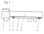
- a weighing device is shown on a vehicle, which consists of four load cell devices 3, 6 between the vehicle frame 2 and the vehicle body, wherein the structure is suspended from the four load cell devices 3, 6 suspended.
- the vehicle body is designed as a loading area 5.
- the weighing device can also be used in rail-bound and other vehicles.
- the illustrated truck 1 has under the loading area 5 a frame 2, which has on each side a longitudinal beam 4, to which two load cell devices 3, 6 are arranged.
- the four load cell devices 3, 6 support the vehicle body 5 at four points relative to the vehicle frame 2 and fix it largely in its vertical and horizontal position.
- the loading area 5 relative to the frame 2 by the load cell devices 3, 6 is suspended like a handle, so that a lateral displacement range of about 10 to 20 mm is provided, which always aligns the load cell device 3, 6 in an inclined position of the vehicle 1 in the direction of gravity ,
- This lateral displacement region encompasses all directions and is essentially dependent on the axial length of the weighing cell device 3, 6.
- a load cell device 3, 6 with a rod-shaped load cell with spherical joints usually has a length of about 100 to 200 mm, so that a lateral displacement range at an angle of 10 to 20 mm sufficient to always ensure a vertical orientation in the direction of gravity.
- the weighing device In the illustrated weighing device four load cell devices 3, 6 are arranged at the corner areas under the vehicle body 5, which are interconnected so that they provide a signal that is directly proportional to the weight of the body 5, together with its contents.
- the weighing device can also consist of three or more than four load cell devices 3, 6.
- a load cell device 3, 6 is shown from the side view of the vehicle 1 in section.
- a part of the vehicle body 5 can be seen on which a downwardly directed rectangular conversion 15 is attached from flat sheet metal parts.
- This conversion 15 has at its lower part via a horizontal sheet metal part 7, which is connected to the vertical sheet metal parts and to which a weight sensor 10 is attached.
- this conversion 15 of the vehicle body 5 laterally projects another slightly smaller conversion 14 into it, which is laterally attached to a longitudinal spar 4 of the vehicle frame 2.
- This smaller tag 14 is V-shaped and open at the bottom and has at the top a horizontal sheet metal part 16 to which the upper side of the weight sensor 10 is attached.
- the weight picker 10 is subjected to tension by the weight of the body 5 and its contents.
- the load cell device 3, 6 basically requires no additional space in the vertical direction between the body 5 and the vehicle frame 2.
- the illustrated conversion parts 15, 14 are directly on the frame 2 or 5 structure welded and thus produce a positive connection.
- the entire load cell device 3, 6 from the conversion parts 15, 14, the weight sensor 10 with its cultivation and evaluation parts can also be provided as a module unit and fastened by fasteners on the vehicle body 5 and vehicle frame 2.
- the weight sensor 10 consists essentially of a rod-shaped deformation body 20, to which strain gauges 13 are applied and which is connected to force introduction and force extraction parts.
- the deformation body is designed as a round rod 20, which terminates in a threaded part 11, 17 at the top and bottom.
- the deformation body can also have square, rectangular or modified cross-sectional shapes.
- the threaded part 11, 17 is in each case connected to a spherical outwardly curved bearing element 12, 18 and forms in each case a force input and force discharge part.
- the spherical bearing elements 12, 18 are also arranged in spherical counter-bearing elements 8, 19, which, however, are curved inward and thus the shape of the force introduction 12 and Aus effets instituten 18 are adapted and form so-called axial spherical plain bearings.
- ball bearings 9 are provided between the bearing 12, 18 and counter bearing elements 8, 19 to reduce friction.
- low-friction plastics such as polytetrafluoroethylene (PTFE) or lubricants are used.
- the counter-bearing elements 8, 19 are attached via a detachable connection in each case to the horizontal conversion parts 7, 16. Due to the spherical design of the force introduction 12 and -austechnischsetti 18 of the weight sensor 10 is vertically aligned by the force of gravity of the hanging vehicle body 5 and this also in a misalignment of the vehicle 1, so that the weight sensor 10 and load cells are always aligned in the direction of gravity.
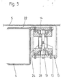
- a load cell device 3, 6 is shown as a cross-sectional view of the direction of travel.
- the similar parts shown in Fig. 2 are provided with the same reference numerals.
- the rotationally symmetrical weight sensor 10 is arranged laterally next to the U-shaped longitudinal spar 4 of the vehicle frame 2 and connected thereto via the smaller rectangular conversion 14.
- the larger conversion 15 is attached to the vehicle body 5 in the upper area.
- a vertical 24 and horizontal distance 22 of about 10 to 20 mm is provided to allow for an inclination of the vehicle 1, a vertical orientation of the weight sensor 10.
- these distances 24, 22 are only necessary during weighing.
- the vehicle body 5 is fixed at least in a horizontal position.
- vertically formed conical bolts are provided, which are inserted from below through holes in the side member 4 in holes of the structure 5.
- Such a locking device can also be done automatically via a hydraulic or pneumatic cylinder or any other type of drive.
- electronic switching and display devices are provided at the same time, which allow a structure weighing only when the locking device is released, so that the structure 5 is aligned kraftnebenschluß arthritis by gravity in the direction of gravity. On the other hand, it is indicated by a defined weight display to the driver that the structure is secured by the lock for driving.
- the locking device can also be done with hydraulic or pneumatic cylinders or inflatable rubber bellows or with any drives that fill or reduce the lateral horizontal gaps 21 between the conversion parts 15, 14 or the conversion parts 15, 14 and the vehicle frame 2. Furthermore, a locking of the structure 5 relative to the vehicle frame 2 can also be effected by cable systems, which are loosened for weighing the structure 5 or the goods.
- a rod-shaped largely rotationally symmetrical load cell is advantageously used, on whose circumference in the central region of the rod 20 strain gauges 13 are applied.
- the deformation of the load cells 10 generate in the strain gauges 13 a signal which is proportional to the weight introduced.
- load cells which are suspended so that the structure is always aligned in the direction of measurement.
- the force 12 and force receiving elements 18 need not be spherical, but may also be designed as a universal joint, as a cone tip bearing, self-aligning ball bearings or comparable design. Only a largely frictionless storage must be provided after all horizontal sides, between which the load cells are arranged.
Landscapes
- Physics & Mathematics (AREA)
- General Physics & Mathematics (AREA)
- Vehicle Body Suspensions (AREA)
- Testing Of Balance (AREA)
Claims (8)
- Dispositif de pesage pour peser des objets sur des véhicules (1), en particulier des objets sur des parties de carrosserie (5) de véhicules (1), où des capteurs de charge (3, 6) sont disposés entre les parties de carrosserie (5) à peser et un châssis de véhicule (2), dont les signaux sont proportionnels au poids des parties de carrosserie (5) et à leur contenu, lesdits capteurs de charge (3, 6) étant reliés à des éléments de paliers oscillants (12, 18) et étant par la force de gravité orientés de telle manière que la direction de la force de gravité soit toujours dans la direction de mesure principale, caractérisé en ce que les capteurs de charge (3, 6) sont réalisés comme cellules de pesage (10) en forme de barres à symétrie de rotation, composées d'une pièce d'admission de force (12), d'un corps de déformation et d'une pièce d'échappement de force (18) disposés successivement dans le sens axial, ledit corps de déformation étant réalisé en tant que barre (20) sur le contour de laquelle des bandes de mesure de dilatation sont appliquées dans la zone centrale et qui peut être contrainte par traction, en ce que la pièce d'admission de force (12) et la pièce d'échappement de force (18) sont réalisées chacune en tant qu'élément de palier sphérique (12, 18), et en ce que la pièce d'admission de force (12) et la pièce d'échappement de force (18) sphériques sont disposées chacune dans un élément de butée de palier (8, 19) également sphérique.
- Dispositif de pesage selon l'une des revendications précédentes, caractérisé en ce qu'au moins trois capteurs de charge (10) sont prévus, disposés entre les parties de carrosserie (5) de véhicule et les parties de châssis de véhicule (2).
- Dispositif de pesage selon l'une des revendications précédentes, caractérisé en ce que des dispositifs de blocage sont prévus entre les parties de châssis (2) et les parties de carrosserie (5), au moyen desquels la carrosserie (5) peut être fixée horizontalement et/ou verticalement par rapport au châssis (2).
- Dispositif de pesage selon l'une des revendications précédentes, caractérisé en ce que des moyens de commutation et/ou d'affichage électroniques sont prévus, lesquels ne valident et n'affichent un pesage que si le dispositif de blocage est desserré et si une plage de translation maximale admissible entre l'admission de charge et l'échappement de charge n'est pas dépassée.
- Dispositif de pesage selon l'une des revendications précédentes, caractérisé en ce que les capteurs de charge (10) sont fixés entre deux pièces d'enceinte (15, 14) disposées l'une autour de l'autre, une des pièces d'enceinte (15) étant mécaniquement raccordée à la carrosserie (5) du véhicule à peser, et l'autre pièce d'enceinte (14) étant mécaniquement raccordée au châssis (2) du véhicule.
- Dispositif de pesage selon l'une des revendications précédentes, caractérisé en ce que les pièces d'enceinte (15, 14) sont réalisées et disposées de manière à ménager au moins en direction verticale un écartement défini entre les pièces d'enceinte (15) du côté d'admission de charge et les pièces d'enceinte (14) du côté d'échappement de charge.
- Dispositif de pesage selon l'une des revendications précédentes, caractérisé en ce que les pièces d'enceinte (15, 14) se composent de trois plaques de tôle (7, 16) disposées l'une sur l'autre dans le sens vertical et raccordées entre elles, les pièces d'enceinte (14, 15) disposées l'une autour de l'autre s'engageant l'une dans l'autre en forme de U avec des ouvertures opposées.
- Dispositif de pesage selon l'une des revendications précédentes, caractérisé en ce que les éléments de butée de palier (8, 19) des éléments de palier de la pièce d'admission de force et de la pièce d'échappement de force sont raccordés chacun à une plaque de tôle (7, 16) des deux pièces d'enceinte (14, 15), disposée horizontalement.
Applications Claiming Priority (2)
| Application Number | Priority Date | Filing Date | Title |
|---|---|---|---|
| DE1999131381 DE19931381A1 (de) | 1999-07-07 | 1999-07-07 | Wägeeinrichtung zum Verwiegen von Gütern auf Fahrzeugen |
| DE19931381 | 1999-07-07 |
Publications (3)
| Publication Number | Publication Date |
|---|---|
| EP1069412A2 EP1069412A2 (fr) | 2001-01-17 |
| EP1069412A3 EP1069412A3 (fr) | 2001-11-07 |
| EP1069412B1 true EP1069412B1 (fr) | 2006-09-13 |
Family
ID=7913959
Family Applications (1)
| Application Number | Title | Priority Date | Filing Date |
|---|---|---|---|
| EP20000114642 Expired - Lifetime EP1069412B1 (fr) | 1999-07-07 | 2000-07-07 | Appareil de pesage pour peser des objets sur des véhicules |
Country Status (2)
| Country | Link |
|---|---|
| EP (1) | EP1069412B1 (fr) |
| DE (2) | DE19931381A1 (fr) |
Cited By (1)
| Publication number | Priority date | Publication date | Assignee | Title |
|---|---|---|---|---|
| WO2016000677A1 (fr) | 2014-07-02 | 2016-01-07 | Hottinger Baldwin Messtechnik Gmbh | Cellule de pesage comprenant un dispositif de centrage hydraulique |
Families Citing this family (2)
| Publication number | Priority date | Publication date | Assignee | Title |
|---|---|---|---|---|
| DE10300087B8 (de) * | 2002-01-07 | 2007-08-23 | Inwatec Gmbh | Messvorrichtung für Eckkräfte von Wagenkästen |
| DE102019127587B4 (de) * | 2019-10-17 | 2025-05-08 | Kurt Willig Gmbh & Co. Kg | Tankfahrzeug mit kardanisch gelagerter Kraftmesszelle |
Family Cites Families (8)
| Publication number | Priority date | Publication date | Assignee | Title |
|---|---|---|---|---|
| DE3042086A1 (de) * | 1980-11-07 | 1982-06-24 | Siemens AG, 1000 Berlin und 8000 München | Waegezelle vom pendelstuetzentyp |
| CH639609A5 (fr) * | 1980-12-09 | 1983-11-30 | Vibro Meter Ag | Camion avec un dispositif de mesure de la charge utile et de la charge sur les essieux dudit camion. |
| DE69115406T2 (de) * | 1990-09-21 | 1996-07-25 | Nuyts Orb N V | Mobiles Gerät zum Wiegen einer Ladung |
| EP0513463A1 (fr) * | 1991-05-17 | 1992-11-19 | Padro i Rubi, D. Ferran | Appareil de pesage pouvant être incorporé dans des véhicules de transport de marchandises |
| NL9101201A (nl) * | 1991-07-09 | 1993-02-01 | Welvaarts B V | Belastingcel en weeginrichting uitgerust met dergelijke belastingcellen. |
| BE1006719A7 (nl) * | 1993-02-15 | 1994-11-22 | Nuyts Orb Nv | Beschermde weegophanging. |
| DE29601398U1 (de) * | 1996-01-27 | 1997-07-24 | Schwelm Anlagenbau GmbH, 58332 Schwelm | Wägeelement |
| DE19619109C1 (de) * | 1996-05-11 | 1998-01-22 | Tedea Huntleigh Europ Ltd | Wägestütze für Fahrzeugaufbauten |
-
1999
- 1999-07-07 DE DE1999131381 patent/DE19931381A1/de not_active Withdrawn
-
2000
- 2000-07-07 EP EP20000114642 patent/EP1069412B1/fr not_active Expired - Lifetime
- 2000-07-07 DE DE50013451T patent/DE50013451D1/de not_active Expired - Lifetime
Cited By (3)
| Publication number | Priority date | Publication date | Assignee | Title |
|---|---|---|---|---|
| WO2016000677A1 (fr) | 2014-07-02 | 2016-01-07 | Hottinger Baldwin Messtechnik Gmbh | Cellule de pesage comprenant un dispositif de centrage hydraulique |
| DE102014009847A1 (de) | 2014-07-02 | 2016-01-07 | Hottinger Baldwin Messtechnik Gmbh | Wägezelle mit hydraulischer Zentriervorrichtung |
| DE102014009847B4 (de) | 2014-07-02 | 2018-03-22 | Hottinger Baldwin Messtechnik Gmbh | Wägezelle mit hydraulischer Zentriervorrichtung |
Also Published As
| Publication number | Publication date |
|---|---|
| DE19931381A1 (de) | 2001-01-11 |
| EP1069412A3 (fr) | 2001-11-07 |
| EP1069412A2 (fr) | 2001-01-17 |
| DE50013451D1 (de) | 2006-10-26 |
Similar Documents
| Publication | Publication Date | Title |
|---|---|---|
| DE102009002188A1 (de) | Kraftaufnehmer zur Messung von Stützkräften in einem Abstützelement | |
| DE102008062249A1 (de) | Standfuss für ein Wägezelle | |
| EP0104557A2 (fr) | Balance | |
| DE19623398A1 (de) | Dachlastenträger für Fahrzeuge | |
| DE10359460B4 (de) | Wägezelle | |
| EP1069412B1 (fr) | Appareil de pesage pour peser des objets sur des véhicules | |
| EP0686839A2 (fr) | Attelage de remorque avec capteur de force | |
| EP0438660B1 (fr) | Dispositif pour mesurer des forces s'exercant latéralement | |
| EP1378732B1 (fr) | Procédé de mesure de la charge des roues sur des véhicules ferroviaires et dispositif de mesure mobile | |
| EP1337816A1 (fr) | Dispositif de pesee pour vehicules sur rails | |
| DE2504992B2 (de) | Waegevorrichtung | |
| DE3833291A1 (de) | Plattformwaage | |
| DE29521150U1 (de) | Wägevorrichtung für ein Fahrzeug | |
| DE3340438A1 (de) | Messanordnung fuer kraftmessungen mittels dehnmessstreifen | |
| DE2300337A1 (de) | Vorrichtung zum wiegen von schienenfahrzeugen | |
| DE3100949C2 (de) | Vorrichtung zum Wägen von Transportfahrzeugen während der Fahrt | |
| DE102005033527B4 (de) | Vorrichtung zur Erfassung von Kräften und/oder Momenten | |
| DE69727924T2 (de) | Vorrichtung zum messen der scherung im kern eines mehrschichtenaufbaus | |
| DE10126661C1 (de) | Elektronische Waage mit mindestens drei Wägezellen | |
| DE2809655A1 (de) | Vorrichtung zur elektromechanischen messung einer kraft | |
| DE4141037C2 (de) | Vorrichtung zum Einleiten einer Last in eine Kraftmeßeinrichtung | |
| EP1141667B1 (fr) | Dispositif de pesage pour vehicules sur rails | |
| DE102010012670B4 (de) | Gabelstapler mit einer Vorrichtung zur Erfassung einer Gewichtsbelastung | |
| DE102010029407A1 (de) | Kraftmessvorrichtung | |
| DE29617085U1 (de) | Plattformwaage |
Legal Events
| Date | Code | Title | Description |
|---|---|---|---|
| PUAI | Public reference made under article 153(3) epc to a published international application that has entered the european phase |
Free format text: ORIGINAL CODE: 0009012 |
|
| AK | Designated contracting states |
Kind code of ref document: A2 Designated state(s): AT BE CH CY DE DK ES FI FR GB GR IE IT LI LU MC NL PT SE Kind code of ref document: A2 Designated state(s): DE FR GB IT NL |
|
| AX | Request for extension of the european patent |
Free format text: AL;LT;LV;MK;RO;SI |
|
| PUAL | Search report despatched |
Free format text: ORIGINAL CODE: 0009013 |
|
| AK | Designated contracting states |
Kind code of ref document: A3 Designated state(s): AT BE CH CY DE DK ES FI FR GB GR IE IT LI LU MC NL PT SE |
|
| AX | Request for extension of the european patent |
Free format text: AL;LT;LV;MK;RO;SI |
|
| RIC1 | Information provided on ipc code assigned before grant |
Free format text: 7G 01G 19/12 A, 7G 01G 19/08 B |
|
| RAP1 | Party data changed (applicant data changed or rights of an application transferred) |
Owner name: HOTTINGER BALDWIN MESSTECHNIK GMBH |
|
| 17P | Request for examination filed |
Effective date: 20020506 |
|
| AKX | Designation fees paid |
Free format text: DE FR GB IT NL |
|
| 17Q | First examination report despatched |
Effective date: 20050520 |
|
| GRAP | Despatch of communication of intention to grant a patent |
Free format text: ORIGINAL CODE: EPIDOSNIGR1 |
|
| GRAS | Grant fee paid |
Free format text: ORIGINAL CODE: EPIDOSNIGR3 |
|
| GRAA | (expected) grant |
Free format text: ORIGINAL CODE: 0009210 |
|
| RAP1 | Party data changed (applicant data changed or rights of an application transferred) |
Owner name: WILL, HEINZ RONALD Owner name: GERLACH, HANS-JOACHIM |
|
| RIN1 | Information on inventor provided before grant (corrected) |
Inventor name: GERLACH, HANS-JOACHIM Inventor name: WILL, HEINZ RONALD |
|
| AK | Designated contracting states |
Kind code of ref document: B1 Designated state(s): DE FR GB IT NL |
|
| PG25 | Lapsed in a contracting state [announced via postgrant information from national office to epo] |
Ref country code: IT Free format text: LAPSE BECAUSE OF FAILURE TO SUBMIT A TRANSLATION OF THE DESCRIPTION OR TO PAY THE FEE WITHIN THE PRESCRIBED TIME-LIMIT;WARNING: LAPSES OF ITALIAN PATENTS WITH EFFECTIVE DATE BEFORE 2007 MAY HAVE OCCURRED AT ANY TIME BEFORE 2007. THE CORRECT EFFECTIVE DATE MAY BE DIFFERENT FROM THE ONE RECORDED. Effective date: 20060913 Ref country code: NL Free format text: LAPSE BECAUSE OF FAILURE TO SUBMIT A TRANSLATION OF THE DESCRIPTION OR TO PAY THE FEE WITHIN THE PRESCRIBED TIME-LIMIT Effective date: 20060913 |
|
| REG | Reference to a national code |
Ref country code: GB Ref legal event code: FG4D Free format text: NOT ENGLISH |
|
| REF | Corresponds to: |
Ref document number: 50013451 Country of ref document: DE Date of ref document: 20061026 Kind code of ref document: P |
|
| GBT | Gb: translation of ep patent filed (gb section 77(6)(a)/1977) |
Effective date: 20061101 |
|
| ET | Fr: translation filed | ||
| NLV1 | Nl: lapsed or annulled due to failure to fulfill the requirements of art. 29p and 29m of the patents act | ||
| PLBE | No opposition filed within time limit |
Free format text: ORIGINAL CODE: 0009261 |
|
| STAA | Information on the status of an ep patent application or granted ep patent |
Free format text: STATUS: NO OPPOSITION FILED WITHIN TIME LIMIT |
|
| 26N | No opposition filed |
Effective date: 20070614 |
|
| GBPC | Gb: european patent ceased through non-payment of renewal fee |
Effective date: 20070707 |
|
| PG25 | Lapsed in a contracting state [announced via postgrant information from national office to epo] |
Ref country code: GB Free format text: LAPSE BECAUSE OF NON-PAYMENT OF DUE FEES Effective date: 20070707 |
|
| REG | Reference to a national code |
Ref country code: FR Ref legal event code: ST Effective date: 20080331 |
|
| PG25 | Lapsed in a contracting state [announced via postgrant information from national office to epo] |
Ref country code: FR Free format text: LAPSE BECAUSE OF NON-PAYMENT OF DUE FEES Effective date: 20070731 |
|
| PGFP | Annual fee paid to national office [announced via postgrant information from national office to epo] |
Ref country code: DE Payment date: 20100922 Year of fee payment: 11 |
|
| PG25 | Lapsed in a contracting state [announced via postgrant information from national office to epo] |
Ref country code: DE Free format text: LAPSE BECAUSE OF NON-PAYMENT OF DUE FEES Effective date: 20130201 |
|
| REG | Reference to a national code |
Ref country code: DE Ref legal event code: R119 Ref document number: 50013451 Country of ref document: DE Effective date: 20130201 |